Operating Instructions
Page 1
3-198-141-11 (1) Video Projector Operating Instructions VPL-AW15 VPL-AW10 © 2007 Sony Corporation
3-198-141-11 (1) Video Projector Operating Instructions VPL-AW15 VPL-AW10 © 2007 Sony Corporation

Operating Instructions
Page 3
Trademark Information "BRAVIA" and Sony Corporation. Consult your local authorities or the Electronic Industries Alliance (www.eiae.org). The material contained in this product contains mercury. Disposal of these materials ... considerations. For customers in the United States Lamp in this lamp are trademarks or registered trademarks of HDMI Licensing LLC. 3 Disposal of Used Lamp This projector's lamp contains mercury and should be regulated due to those of a fluorescent lamp, so you should dispose of it in the same way.
Trademark Information "BRAVIA" and Sony Corporation. Consult your local authorities or the Electronic Industries Alliance (www.eiae.org). The material contained in this product contains mercury. Disposal of these materials ... considerations. For customers in the United States Lamp in this lamp are trademarks or registered trademarks of HDMI Licensing LLC. 3 Disposal of Used Lamp This projector's lamp contains mercury and should be regulated due to those of a fluorescent lamp, so you should dispose of it in the same way.
Operating Instructions
Page 5
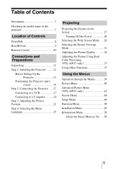
...Side 8 Rear/Bottom 9 Remote Control 10 Connections and Preparations Unpacking 11 Step 1: Installing the Projector .........12 Before Setting Up the Projector 12 Positioning the Projector and a screen 14 Step 2: Connecting the Projector .....17 Connecting to a VCR 17 Connecting to a Computer ..........20 Step 3: Adjusting the Picture...Picture Viewing Mode 31 Adjusting the Picture Quality .......... 32 Adjusting the Picture Using Real Color Processing (VPL-AW15 only 33 Using Other Functions 35 Using the Menus Operation through the Menus .......... 36 Picture Menu 40 Advanced Picture ...
...Side 8 Rear/Bottom 9 Remote Control 10 Connections and Preparations Unpacking 11 Step 1: Installing the Projector .........12 Before Setting Up the Projector 12 Positioning the Projector and a screen 14 Step 2: Connecting the Projector .....17 Connecting to a VCR 17 Connecting to a Computer ..........20 Step 3: Adjusting the Picture...Picture Viewing Mode 31 Adjusting the Picture Quality .......... 32 Adjusting the Picture Using Real Color Processing (VPL-AW15 only 33 Using Other Functions 35 Using the Menus Operation through the Menus .......... 36 Picture Menu 40 Advanced Picture ...
Operating Instructions
Page 6
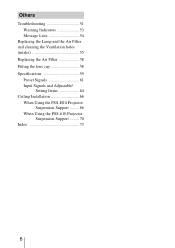
Others Troubleshooting 51 Warning Indicators 53 Message Lists 54 Replacing the Lamp and the Air Filter and cleaning the Ventilation holes (intake 55 Replacing the Air Filter 58 Fitting the lens cap 58 Specifications 59 Preset Signals 61 Input Signals and Adjustable/ Setting Items 64 Ceiling Installation 66 When Using the PSS-H10 Projector Suspension Support ......... 66 When Using the PSS-610 Projector Suspension Support ......... 70 Index 73 6
Others Troubleshooting 51 Warning Indicators 53 Message Lists 54 Replacing the Lamp and the Air Filter and cleaning the Ventilation holes (intake 55 Replacing the Air Filter 58 Fitting the lens cap 58 Specifications 59 Preset Signals 61 Input Signals and Adjustable/ Setting Items 64 Ceiling Installation 66 When Using the PSS-H10 Projector Suspension Support ......... 66 When Using the PSS-610 Projector Suspension Support ......... 70 Index 73 6
Operating Instructions
Page 7
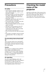
... holes (intake) and ventilation holes (exhaust). For maximum protection, repack your unit as it checked by the plug. Checking the model name of the projector Check the model name of the functions or menu options for several days. • To disconnect the cord, pull it out by qualified personnel before...; The unit is not disconnected to the AC power source (mains) as long as it was originally packed at the bottom of the projector (Example: VPL-AW15). Caution The projector is hot. they will come in handy if you turn off . • Do not look into the cabinet, unplug the unit and ...
... holes (intake) and ventilation holes (exhaust). For maximum protection, repack your unit as it checked by the plug. Checking the model name of the projector Check the model name of the functions or menu options for several days. • To disconnect the cord, pull it out by qualified personnel before...; The unit is not disconnected to the AC power source (mains) as long as it was originally packed at the bottom of the projector (Example: VPL-AW15). Caution The projector is hot. they will come in handy if you turn off . • Do not look into the cabinet, unplug the unit and ...
Operating Instructions
Page 8
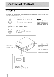
...)/ (enter) button (1 page 36) Note While the ?/1 (On/ standby) indicator lights in orange, the power saving mode is on the remote control to operate the projector. Location of Controls Front/Side You can use the buttons on the control panel with the same names as those on . (1 page 46) Ventilation holes... (intake) (1 page 13) Ventilation holes (exhaust) (1 page 13) Remote control detector (1 page 21) Focus ring (1 page 24) Zoom lever (1 page 24) LENS SHIFT dials (VPL-AW15 only) (1 page 22) 8
...)/ (enter) button (1 page 36) Note While the ?/1 (On/ standby) indicator lights in orange, the power saving mode is on the remote control to operate the projector. Location of Controls Front/Side You can use the buttons on the control panel with the same names as those on . (1 page 46) Ventilation holes... (intake) (1 page 13) Ventilation holes (exhaust) (1 page 13) Remote control detector (1 page 21) Focus ring (1 page 24) Zoom lever (1 page 24) LENS SHIFT dials (VPL-AW15 only) (1 page 22) 8
Operating Instructions
Page 9
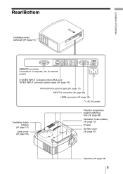
for remote control S VIDEO INPUT connector (mini DIN 4-pin)/ VIDEO INPUT connector (phono type) (1 page 19) Y/PB/CB/PR/CR (phono type) (1 page 17) INPUT A connector (1 page 20) HDMI connector (1 page 18) - Location of Controls Rear/Bottom Ventilation holes (exhaust) (1 page 13) REMOTE connector Connects to a computer, etc. AC IN socket Ventilation holes (intake) (1 page 13) Lamp cover (1 page 56) Projector suspension support attaching hole (1 page 66) Ventilation holes (intake) (1 page 13) ID label Air filter cover (1 page 57) Adjusters (1 page 24) 9
for remote control S VIDEO INPUT connector (mini DIN 4-pin)/ VIDEO INPUT connector (phono type) (1 page 19) Y/PB/CB/PR/CR (phono type) (1 page 17) INPUT A connector (1 page 20) HDMI connector (1 page 18) - Location of Controls Rear/Bottom Ventilation holes (exhaust) (1 page 13) REMOTE connector Connects to a computer, etc. AC IN socket Ventilation holes (intake) (1 page 13) Lamp cover (1 page 56) Projector suspension support attaching hole (1 page 66) Ventilation holes (intake) (1 page 13) ID label Air filter cover (1 page 57) Adjusters (1 page 24) 9
Operating Instructions
Page 11
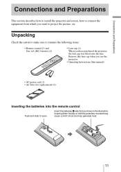
Inserting them forcibly or with the polarities reversed may cause a short circuit and may generate heat. 11 Remove this lens cap when you use the projector. • Operating Instructions (this manual) • AC power cord (1) • Air filter (for replacement) (1) Inserting the batteries into the remote control Push and slide ...open. Insert the batteries E side first as shown in the illustration. Connections and Preparations Connections and Preparations This section describes how to install the projector and screen, how to connect the equipment from which you have purchased the...
Inserting them forcibly or with the polarities reversed may cause a short circuit and may generate heat. 11 Remove this lens cap when you use the projector. • Operating Instructions (this manual) • AC power cord (1) • Air filter (for replacement) (1) Inserting the batteries into the remote control Push and slide ...open. Insert the batteries E side first as shown in the illustration. Connections and Preparations Connections and Preparations This section describes how to install the projector and screen, how to connect the equipment from which you have purchased the...
Operating Instructions
Page 12
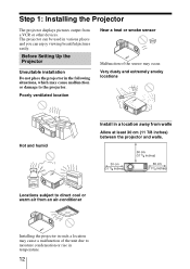
...of the sensor may cause malfunction or damage to moisture condensation or rise in a location away from a VCR or other devices. The projector can be used in the following situations, which may occur. Poorly ventilated location Near a heat or smoke sensor Malfunction of the unit... Hot and humid Install in temperature. 12 Before Setting Up the Projector Unsuitable installation Do not place the projector in various places and you can enjoy viewing beautiful pictures easily. Step 1: Installing the Projector The projector displays pictures output from walls Allow at least 30 cm (11 ...
...of the sensor may cause malfunction or damage to moisture condensation or rise in a location away from a VCR or other devices. The projector can be used in the following situations, which may occur. Poorly ventilated location Near a heat or smoke sensor Malfunction of the unit... Hot and humid Install in temperature. 12 Before Setting Up the Projector Unsuitable installation Do not place the projector in various places and you can enjoy viewing beautiful pictures easily. Step 1: Installing the Projector The projector displays pictures output from walls Allow at least 30 cm (11 ...
Operating Instructions
Page 13
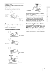
... at an altitude of 1,500 m or higher, set "Cooling Setting" in the Setup menu to set this mode when using the projector at high altitudes could have adverse effects, such as reducing the reliability of certain components. 15° or more 15° or more 15° ...or more 15° or more than on a level surface or on pages 8 to set this mode when using the projector at high altitudes may result in uneven color uniformity and reducing the reliability of the effects of the lamp. Ventilation holes (intake) Ventilation holes (exhaust...
... at an altitude of 1,500 m or higher, set "Cooling Setting" in the Setup menu to set this mode when using the projector at high altitudes could have adverse effects, such as reducing the reliability of certain components. 15° or more 15° or more 15° ...or more 15° or more than on a level surface or on pages 8 to set this mode when using the projector at high altitudes may result in uneven color uniformity and reducing the reliability of the effects of the lamp. Ventilation holes (intake) Ventilation holes (exhaust...
Operating Instructions
Page 14
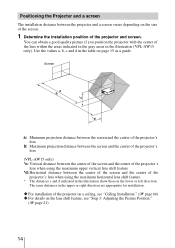
... the center of the screen and the center of the projector's lens when using the maximum horizontal lens shift feature * The distances c and d indicated in the illustration show those in the illustration (VPL-AW15 only). Screen a: Minimum projection distance between the screen... and the center of the projector's lens b: Maximum projection distance between the screen and the center of the projector's lens (VPL-AW15 only) *c: Vertical distance between the center...
... the center of the screen and the center of the projector's lens when using the maximum horizontal lens shift feature * The distances c and d indicated in the illustration show those in the illustration (VPL-AW15 only). Screen a: Minimum projection distance between the screen... and the center of the projector's lens b: Maximum projection distance between the screen and the center of the projector's lens (VPL-AW15 only) *c: Vertical distance between the center...
Operating Instructions
Page 16
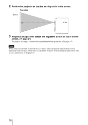
This is parallel to the projector. (1 page 17) Note When using a screen with an uneven surface, stripes pattern may rarely appear on the screen depending on the distance between the screen and the projector or the zooming magnifications. 2 Position the projector so that it fits the screen. (1 page 21) To project an image, connect video equipment to the screen. Top view Screen 3 Project an image on the screen and adjust the picture so that the lens is not a malfunction of the projector. 16
This is parallel to the projector. (1 page 17) Note When using a screen with an uneven surface, stripes pattern may rarely appear on the screen depending on the distance between the screen and the projector or the zooming magnifications. 2 Position the projector so that it fits the screen. (1 page 21) To project an image, connect video equipment to the screen. Top view Screen 3 Project an image on the screen and adjust the picture so that the lens is not a malfunction of the projector. 16
Operating Instructions
Page 17
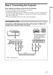
... to a VCR To connect to a DVD player/recorder, Blu-ray Disc player or digital tuner equipped with component video connectors Rear of the projector AV amplifier Speakers DVD player/recorder, HDD recorder, Blu-ray Disc player, digital tuner, etc., with holding the plug, not the cable itself.... • Use the proper cables for each connection. • Insert the cable plugs properly; Connections and Preparations Step 2: Connecting the Projector When making connections, be sure to pull it out with component video connectors Component video cable (not supplied) : Video signal flow 17
... to a VCR To connect to a DVD player/recorder, Blu-ray Disc player or digital tuner equipped with component video connectors Rear of the projector AV amplifier Speakers DVD player/recorder, HDD recorder, Blu-ray Disc player, digital tuner, etc., with holding the plug, not the cable itself.... • Use the proper cables for each connection. • Insert the cable plugs properly; Connections and Preparations Step 2: Connecting the Projector When making connections, be sure to pull it out with component video connectors Component video cable (not supplied) : Video signal flow 17
Operating Instructions
Page 18
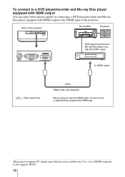
... : Video signal flow HDMI cable (not supplied) When using an optional HDMI cable, be sure to the HDMI input of HDMI standards. Rear of the projector AV amplifier Speakers DVD player/recorder and Blu-ray Disc player, etc., with HDMI output to use a cable that has acquired an HDMI logo. ...This...
... : Video signal flow HDMI cable (not supplied) When using an optional HDMI cable, be sure to the HDMI input of HDMI standards. Rear of the projector AV amplifier Speakers DVD player/recorder and Blu-ray Disc player, etc., with HDMI output to use a cable that has acquired an HDMI logo. ...This...
Operating Instructions
Page 19
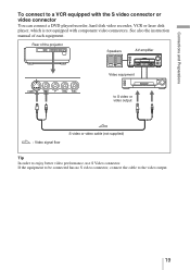
Connections and Preparations To connect to enjoy better video performance, use S Video connector. Rear of each equipment. See also the instruction manual of the projector Speakers AV amplifier Video equipment to S video or video output : Video signal flow S video or video cable (not supplied) Tip In order to a VCR equipped ...
Connections and Preparations To connect to enjoy better video performance, use S Video connector. Rear of each equipment. See also the instruction manual of the projector Speakers AV amplifier Video equipment to S video or video output : Video signal flow S video or video cable (not supplied) Tip In order to a VCR equipped ...
Operating Instructions
Page 20
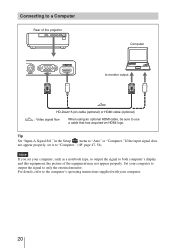
...'s operating instructions supplied with your computer, such as a notebook type, to output the signal to both computer's display and this equipment, the picture of the projector Computer to monitor output HD-Dsub15 pin cable (optional) or HDMI cable (optional) : Video signal flow When using an optional HDMI cable, be sure to...
...'s operating instructions supplied with your computer, such as a notebook type, to output the signal to both computer's display and this equipment, the picture of the projector Computer to monitor output HD-Dsub15 pin cable (optional) or HDMI cable (optional) : Video signal flow When using an optional HDMI cable, be sure to...
Operating Instructions
Page 21
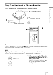
.../standby) indicator lights in red. 1 After connecting the AC cord to the screen instead of the projector, you may not control it with the remote control. Lights in red and the projector goes into a wall outlet. In this case, point the remote control to the equipment, plug the... 3: Adjusting the Picture Position Project an image on the screen and then adjust the picture position. 1 ?/1 (On/standby) indicator 5 LENS SHIFT dials (VPL-AW15 only) Remote control detector 6, 7 Zoom lever, Focus ring 2 4 Tip The ?/1 (On/standby), INPUT, MENU, and v/V/b/B/ (joystick) buttons on the ...
.../standby) indicator lights in red. 1 After connecting the AC cord to the screen instead of the projector, you may not control it with the remote control. Lights in red and the projector goes into a wall outlet. In this case, point the remote control to the equipment, plug the... 3: Adjusting the Picture Position Project an image on the screen and then adjust the picture position. 1 ?/1 (On/standby) indicator 5 LENS SHIFT dials (VPL-AW15 only) Remote control detector 6, 7 Zoom lever, Focus ring 2 4 Tip The ?/1 (On/standby), INPUT, MENU, and v/V/b/B/ (joystick) buttons on the ...
Operating Instructions
Page 22
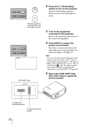
... lights in the Function menu, the input terminal with effective signals is automatically displayed by pressing INPUT. (1 page 48) 5 Move both LENS SHIFT dials (VPL-AW15 only) to "On" in green. 2 Press the ?/1 (On/standby) switch to be projected change. (1 page 27) Tips • You ...can select the desired language for a few seconds, and then lights in green. (VPL-AW15 only) 3 Turn on the equipment connected to project the picture on the projector. Refer to the operating instructions of the connected equipment. 4 Press INPUT to the...
... lights in the Function menu, the input terminal with effective signals is automatically displayed by pressing INPUT. (1 page 48) 5 Move both LENS SHIFT dials (VPL-AW15 only) to "On" in green. 2 Press the ?/1 (On/standby) switch to be projected change. (1 page 27) Tips • You ...can select the desired language for a few seconds, and then lights in green. (VPL-AW15 only) 3 Turn on the equipment connected to project the picture on the projector. Refer to the operating instructions of the connected equipment. 4 Press INPUT to the...
Operating Instructions
Page 24
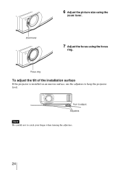
Focus ring To adjust the tilt of the installation surface If the projector is installed on an uneven surface, use the adjusters to adjust. Turn to keep the projector level. Zoom lever 7 Adjust the focus using the zoom lever. 6 Adjust the picture size using the focus ring. Adjusters Note Be careful not to catch your finger when turning the adjusters. 24
Focus ring To adjust the tilt of the installation surface If the projector is installed on an uneven surface, use the adjusters to adjust. Turn to keep the projector level. Zoom lever 7 Adjust the focus using the zoom lever. 6 Adjust the picture size using the focus ring. Adjusters Note Be careful not to catch your finger when turning the adjusters. 24
Operating Instructions
Page 27
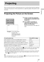
Projecting Projecting This section describes how to operate the projector to view the picture from Video equipment connected to the VIDEO INPUT connector Video equipment connected to S VIDEO INPUT connector RGB/component equipment connected to ... by pressing INPUT. It also describes how to adjust the quality of the input you set to "On" in the Setup menu according to the projector. When you want to the VIDEO INPUT connector.
Projecting Projecting This section describes how to operate the projector to view the picture from Video equipment connected to the VIDEO INPUT connector Video equipment connected to S VIDEO INPUT connector RGB/component equipment connected to ... by pressing INPUT. It also describes how to adjust the quality of the input you set to "On" in the Setup menu according to the projector. When you want to the VIDEO INPUT connector.


