Service Manual
Page 1
...Parts for installation and connections (1 set) Design and specifications are subject to 131°F) Dimensions Approx. 262 × 90 × 185 mm (10 3/8 × 3 5/8 × 7 3/8 in.) (w/h/d) not incl. SERVICE MANUAL Ver 1.1 2002.08 CDX-757MX... US Model Canadian Model E Model Model Name Using Similar Mechanism CD Drive Mechanism Type Optical Pick-up Name CDX-747X MG-251B-137 KSS-720A ... pins) Analog audio output (RCA pin) Current drain 800 mA (during CD playback) 800 mA (during loading or ejecting a disc) Operating temperature -...
...Parts for installation and connections (1 set) Design and specifications are subject to 131°F) Dimensions Approx. 262 × 90 × 185 mm (10 3/8 × 3 5/8 × 7 3/8 in.) (w/h/d) not incl. SERVICE MANUAL Ver 1.1 2002.08 CDX-757MX... US Model Canadian Model E Model Model Name Using Similar Mechanism CD Drive Mechanism Type Optical Pick-up Name CDX-747X MG-251B-137 KSS-720A ... pins) Analog audio output (RCA pin) Current drain 800 mA (during CD playback) 800 mA (during loading or ejecting a disc) Operating temperature -...
Service Manual
Page 2
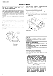
... optical pick-up block is concentrated so as to be handled with care. REPLACE THESE COMPONENTS WITH SONY PARTS WHOSE PART NUMBERS APPEAR AS SHOWN IN THIS MANUAL OR IN SUPPLEMENTS PUBLISHED BY SONY. LES COMPOSANTS IDENTIFIÉS PAR UNE MARQUE 0 SUR LES DIAGRAMMES SCHÉMATIQUES ET LA LISTE... DES PIÈCES SONT CRITIQUES POUR LA SÉCURITÉ DE FONCTIONNEMENT. CDX-757MX SERVICING NOTES NOTES ON ...
... optical pick-up block is concentrated so as to be handled with care. REPLACE THESE COMPONENTS WITH SONY PARTS WHOSE PART NUMBERS APPEAR AS SHOWN IN THIS MANUAL OR IN SUPPLEMENTS PUBLISHED BY SONY. LES COMPOSANTS IDENTIFIÉS PAR UNE MARQUE 0 SUR LES DIAGRAMMES SCHÉMATIQUES ET LA LISTE... DES PIÈCES SONT CRITIQUES POUR LA SÉCURITÉ DE FONCTIONNEMENT. CDX-757MX SERVICING NOTES NOTES ON ...
Service Manual
Page 3
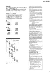
... disc information in the disc magazine. Test disc for CD-R: TCD-R082LMT (Part No.: J-2502-063-1) Test disc for CD-RW: TCD-W082L (Part No.: J-2502-063-2) Notes on CD-R/CD-RW discs • You can play CD-Rs/CD-RWs (recordable CDs/rewritable CDs) on this set, use the following cases, elapsed...." As of data using the TrackAt-Once method. Example: At 64 kbytes, it may play a CD-R/CD-RW that enables adding of December, 2001 3 CDX-757MX TEST DISC This set can playback a CD-R, CD-RW for audio use a disc recorded in Multi Session*2. *1 ISO 9660 Format The most common international...
... disc information in the disc magazine. Test disc for CD-R: TCD-R082LMT (Part No.: J-2502-063-1) Test disc for CD-RW: TCD-W082L (Part No.: J-2502-063-2) Notes on CD-R/CD-RW discs • You can play CD-Rs/CD-RWs (recordable CDs/rewritable CDs) on this set, use the following cases, elapsed...." As of data using the TrackAt-Once method. Example: At 64 kbytes, it may play a CD-R/CD-RW that enables adding of December, 2001 3 CDX-757MX TEST DISC This set can playback a CD-R, CD-RW for audio use a disc recorded in Multi Session*2. *1 ISO 9660 Format The most common international...
Service Manual
Page 4
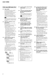
...support a disk of folders or files to play a disc to the MP3 file name. Q8 Can the unit play ? CDX-757MX FAQ- Copyright law prohibits copying, distributing, or delivering all or part of the track), sound is inaccurate. A folder name or a file name with no playback occur. Pay attention to ....2 is 8. On this unit. MPEG1 MPEG2 48kHz 24kHz 44.1kHz 22.05kHz 32kHz 16kHz Q12 Does the unit support the play a CD-R/RW containing both music CD data (CD-DA) and MP3 file data? About ID3 tag version 2 Although not a malfunction, the following points about the bit rate regarding playback...
...support a disk of folders or files to play a disc to the MP3 file name. Q8 Can the unit play ? CDX-757MX FAQ- Copyright law prohibits copying, distributing, or delivering all or part of the track), sound is inaccurate. A folder name or a file name with no playback occur. Pay attention to ....2 is 8. On this unit. MPEG1 MPEG2 48kHz 24kHz 44.1kHz 22.05kHz 32kHz 16kHz Q12 Does the unit support the play a CD-R/RW containing both music CD data (CD-DA) and MP3 file data? About ID3 tag version 2 Although not a malfunction, the following points about the bit rate regarding playback...
Service Manual
Page 5
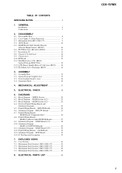
... Diagram - Schematic Diagram - Assembly Flow 15 3-2. Operation Check 16 4. Block Diagram - IC Pin Function Description 39 7. Mechanism Deck Section-2 (MG-251B-137 43 7-4. ELECTRICAL PARTS LIST 46 CDX-757MX 5 Disassembly Flow 8 2-2. Optical Pick-up (KSS-720A 13 2-12. Block Diagram - RF/LSW Boards 24 6-6. MAIN Board (1/3 28 6-10. MAIN (2/3)/SWITCH Boards 29 6-11...
... Diagram - Schematic Diagram - Assembly Flow 15 3-2. Operation Check 16 4. Block Diagram - IC Pin Function Description 39 7. Mechanism Deck Section-2 (MG-251B-137 43 7-4. ELECTRICAL PARTS LIST 46 CDX-757MX 5 Disassembly Flow 8 2-2. Optical Pick-up (KSS-720A 13 2-12. Block Diagram - RF/LSW Boards 24 6-6. MAIN Board (1/3 28 6-10. MAIN (2/3)/SWITCH Boards 29 6-11...
Service Manual
Page 18
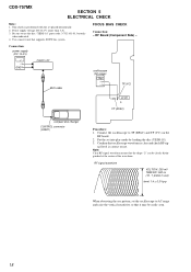
...) level: 1.4 ± 0.3 Vp-p When observing the eye pattern, set into play mode by loading the disc (YEDS-18). 3. Confirm that supports SONY bus system. nal level is performed with the set placed horizontally. 2. FOCUS BIAS CHECK Connection: - Note: Clear RF signal waveform means that it may be...the waveform. RF Board (Component Side) - RF signal waveform VOLT/DIV: 200 mV TIME/DIV: 500 ns (10 : 1 probe in use the disc "YEDS-18" parts code: 3-702-101-01, but only when indicated. 4. Power supply voltage: DC14.4 V (more than 3 A). 3. TP (VC) IC101 TP (RFAC) compact disc ...
...) level: 1.4 ± 0.3 Vp-p When observing the eye pattern, set into play mode by loading the disc (YEDS-18). 3. Confirm that supports SONY bus system. nal level is performed with the set placed horizontally. 2. FOCUS BIAS CHECK Connection: - Note: Clear RF signal waveform means that it may be...the waveform. RF Board (Component Side) - RF signal waveform VOLT/DIV: 200 mV TIME/DIV: 500 ns (10 : 1 probe in use the disc "YEDS-18" parts code: 3-702-101-01, but only when indicated. 4. Power supply voltage: DC14.4 V (more than 3 A). 3. TP (VC) IC101 TP (RFAC) compact disc ...
Service Manual
Page 23
... indicated except for safety. J : CD PLAY • Circuit Boards Location JACK board SWITCH board LSW board CDX-757MX MAIN board RF board 23 23 Replace only with a oscilloscope. 6-4. NOTE FOR PRINTED WIRING BOARDS AND SCHEMATIC DIAGRAMS Note on Printed Wiring Board: • X : parts extracted from the component side. • Y : parts extracted from the conductor side...
... indicated except for safety. J : CD PLAY • Circuit Boards Location JACK board SWITCH board LSW board CDX-757MX MAIN board RF board 23 23 Replace only with a oscilloscope. 6-4. NOTE FOR PRINTED WIRING BOARDS AND SCHEMATIC DIAGRAMS Note on Printed Wiring Board: • X : parts extracted from the component side. • Y : parts extracted from the conductor side...
Service Manual
Page 41
...CDX-757MX The components identified by mark 0 or dotted line with part number specified. Replace only with mark 0 are critical for routine service. No. 1 2 *3 4 5 Part No. NOTE: • -XX and -X mean standardized parts, so they may have some difference from the original one. • Color Indication of Appearance Parts Example: KNOB, BALANCE (WHITE) . . . (RED) ↑ ↑ Parts... Items marked "*" are not stocked since they are given in the last of the electrical parts list. Some delay should be anticipated when ordering these items. • Accessories are seldom required...
...CDX-757MX The components identified by mark 0 or dotted line with part number specified. Replace only with mark 0 are critical for routine service. No. 1 2 *3 4 5 Part No. NOTE: • -XX and -X mean standardized parts, so they may have some difference from the original one. • Color Indication of Appearance Parts Example: KNOB, BALANCE (WHITE) . . . (RED) ↑ ↑ Parts... Items marked "*" are not stocked since they are given in the last of the electrical parts list. Some delay should be anticipated when ordering these items. • Accessories are seldom required...

Service Manual
Page 42
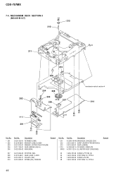
CDX-757MX 7-2. S) SUB ASSY 3-024-161-01 SPRING (SUT) Remark Ref. No. 101 102 Part No. No. 103 #3 Part No. Description X-3378-091-1 CHASSIS (U. Description 3-011-997-01 SPRING (STOPPER. LOWER) 7-685-781-09 SCREW +PTT 2X4 (S) Remark 42 MECHANISM DECK SECTION-1 (MG-251B-137) 101 #3 #3 #3 102 103 mechanism deck section-3 mechanism deck section-2 Ref.
CDX-757MX 7-2. S) SUB ASSY 3-024-161-01 SPRING (SUT) Remark Ref. No. 101 102 Part No. No. 103 #3 Part No. Description X-3378-091-1 CHASSIS (U. Description 3-011-997-01 SPRING (STOPPER. LOWER) 7-685-781-09 SCREW +PTT 2X4 (S) Remark 42 MECHANISM DECK SECTION-1 (MG-251B-137) 101 #3 #3 #3 102 103 mechanism deck section-3 mechanism deck section-2 Ref.
Service Manual
Page 44
... (LOAD 1) ASSY 209 3-010-252-11 ROLLER (CRE) 210 3-010-268-01 SPRING (DH), TENSION Ref. No. * 211 212 213 * 214 M103 Part No. No. * 201 * 202 204 205 206 Part No. Description A-3290-194-M MAIN ASSY, CHASSIS (EVY) 3-010-254-11 SHAFT (ROTARY PREVENTION C) 3-010-253-01 GEAR (LOMINI) A-3326-947...-781-09 SCREW +PTT 2X4 (S) #4 7-624-104-04 STOP RING 2.0, TYPE-E #6 7-628-253-00 SCREW +PS 2X4 #8 7-624-102-04 STOP RING 1.5, TYPE-E Remark 44 CDX-757MX 7-4. Description 3-024-150-01 RETAINER (CHM) X-3378-080-1 BRACKET (CHM.
... (LOAD 1) ASSY 209 3-010-252-11 ROLLER (CRE) 210 3-010-268-01 SPRING (DH), TENSION Ref. No. * 211 212 213 * 214 M103 Part No. No. * 201 * 202 204 205 206 Part No. Description A-3290-194-M MAIN ASSY, CHASSIS (EVY) 3-010-254-11 SHAFT (ROTARY PREVENTION C) 3-010-253-01 GEAR (LOMINI) A-3326-947...-781-09 SCREW +PTT 2X4 (S) #4 7-624-104-04 STOP RING 2.0, TYPE-E #6 7-628-253-00 SCREW +PS 2X4 #8 7-624-102-04 STOP RING 1.5, TYPE-E Remark 44 CDX-757MX 7-4. Description 3-024-150-01 RETAINER (CHM) X-3378-080-1 BRACKET (CHM.
Service Manual
Page 45
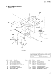
... 1-676-341-11 OP FLEXIBLE BOARD 3-025-743-01 SPRING (FEED), LEAF X-3378-101-2 HOLDER (SLED. MECHANISM DECK SECTION-4 (MG-251B-137) #10 CDX-757MX 259 258 #7 256 not supplied 257 #11 255 254 260 252 M101 #5 253 #11 not supplied M102 not supplied 251 not supplied The components identified... by mark 0 or dotted line with part number specified. No. 251 252 253 254 0 255 Part No. 7-5. S) ASSY 3-931-832-01 GEAR (SL MIDWAY) 8-820-103-11 OPTICAL PICK-UP KSS-720A/C-RP Remark Ref...
... 1-676-341-11 OP FLEXIBLE BOARD 3-025-743-01 SPRING (FEED), LEAF X-3378-101-2 HOLDER (SLED. MECHANISM DECK SECTION-4 (MG-251B-137) #10 CDX-757MX 259 258 #7 256 not supplied 257 #11 255 254 260 252 M101 #5 253 #11 not supplied M102 not supplied 251 not supplied The components identified... by mark 0 or dotted line with part number specified. No. 251 252 253 254 0 255 Part No. 7-5. S) ASSY 3-931-832-01 GEAR (SL MIDWAY) 8-820-103-11 OPTICAL PICK-UP KSS-720A/C-RP Remark Ref...
Service Manual
Page 46
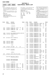
... Replace only with mark 0 are critical for example: uA. . : µA. . When indicating parts by mark 0 or dotted line with part number specified. Part No. C106 C107 C108 C109 Part No. No. ing these items. • SEMICONDUCTORS In each case, u: µ, for safety....684-650-11 JACK BOARD *********** < CAPACITOR > Remark Ref. Ref. CDX-757MX JACK LSW MAIN SECTION 8 ELECTRICAL PARTS LIST NOTE: • Due to standardization, replacements in the parts list may have some difference from the parts specified in the diagrams or the components used on the set. &#...
... Replace only with mark 0 are critical for example: uA. . : µA. . When indicating parts by mark 0 or dotted line with part number specified. Part No. C106 C107 C108 C109 Part No. No. ing these items. • SEMICONDUCTORS In each case, u: µ, for safety....684-650-11 JACK BOARD *********** < CAPACITOR > Remark Ref. Ref. CDX-757MX JACK LSW MAIN SECTION 8 ELECTRICAL PARTS LIST NOTE: • Due to standardization, replacements in the parts list may have some difference from the parts specified in the diagrams or the components used on the set. &#...
Service Manual
Page 49
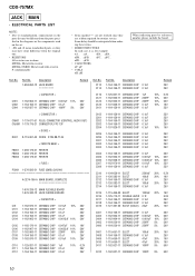
...VAR, SLIDE 10K (ELEVATOR HEIGHT SENSOR ACCESSORIES 3-241-142-11 MANUAL, INSRTUCTION (ENGLISH, FRENCH, TRADITIONAL CHINESE) A-3301-944-A MAGAZINE (250) ASSY PARTS FOR INSTALLATION AND CONNECTIONS 501 * 502 503 504 3-040-583-21 BRACKET (T) X-3369-824-1 SCREW ASSY 1-590-874-11 CORD, CONNECTION (RCA... PIN CORD) 1-590-519-21 CORD (WITH CONNECTOR) (BUS CABLE) Description CDX-757MX RF SWITCH Remark 501 502 BRACKET (T) × 2 503 +PSW4 × 10 × 4 TAPPING SCREW (DIA.5 × 20) × 4 SCREW ASSY...
...VAR, SLIDE 10K (ELEVATOR HEIGHT SENSOR ACCESSORIES 3-241-142-11 MANUAL, INSRTUCTION (ENGLISH, FRENCH, TRADITIONAL CHINESE) A-3301-944-A MAGAZINE (250) ASSY PARTS FOR INSTALLATION AND CONNECTIONS 501 * 502 503 504 3-040-583-21 BRACKET (T) X-3369-824-1 SCREW ASSY 1-590-874-11 CORD, CONNECTION (RCA... PIN CORD) 1-590-519-21 CORD (WITH CONNECTOR) (BUS CABLE) Description CDX-757MX RF SWITCH Remark 501 502 BRACKET (T) × 2 503 +PSW4 × 10 × 4 TAPPING SCREW (DIA.5 × 20) × 4 SCREW ASSY...
Service Manual
Page 50
...Change of MAIN/SWITCH/JACK boards. (Suffix-12) (ECN-CSA06141) In this set, MAIN, SWITCH and JACK boards have been changed parts list are printing error in the Part No. Former : 1-684-650-11 New : 1-684-650-12 1 Former : -11 New : -12 - Printed wiring ... SWITCH BOARD (Conductor Side) - 1 Former : -11 New : -12 SERVICE MANUAL Ver 1.1 2002.08 CDX-757MX US Model Canadian Model E Model SUPPLEMENT-1 File this supplement with their suffix number the Part No. Refer to original service manual for other information. • NEW/FORMER DISCRIMINATION Former and new board can...
...Change of MAIN/SWITCH/JACK boards. (Suffix-12) (ECN-CSA06141) In this set, MAIN, SWITCH and JACK boards have been changed parts list are printing error in the Part No. Former : 1-684-650-11 New : 1-684-650-12 1 Former : -11 New : -12 - Printed wiring ... SWITCH BOARD (Conductor Side) - 1 Former : -11 New : -12 SERVICE MANUAL Ver 1.1 2002.08 CDX-757MX US Model Canadian Model E Model SUPPLEMENT-1 File this supplement with their suffix number the Part No. Refer to original service manual for other information. • NEW/FORMER DISCRIMINATION Former and new board can...
Service Manual
Page 51
...8226; Circled numbers refer to waveforms. • Signal path. CDX-757MX • DIAGRAMS NOTE FOR PRINTED WIRING BOARDS AND SCHEMATIC DIAGRAMS Note on Printed Wiring Board: • X : parts extracted from the component side. • Y : parts extracted from the conductor side. • f : internal component..... • H : adjustment for repair. • Power voltage is dc 14.4V and fed with regulated dc power supply from CD changer controller. • Voltages and waveforms are dc with respect to normal production tolerances. • Waveforms are taken with a VOM (Input impedance 10 ...
...8226; Circled numbers refer to waveforms. • Signal path. CDX-757MX • DIAGRAMS NOTE FOR PRINTED WIRING BOARDS AND SCHEMATIC DIAGRAMS Note on Printed Wiring Board: • X : parts extracted from the component side. • Y : parts extracted from the conductor side. • f : internal component..... • H : adjustment for repair. • Power voltage is dc 14.4V and fed with regulated dc power supply from CD changer controller. • Voltages and waveforms are dc with respect to normal production tolerances. • Waveforms are taken with a VOM (Input impedance 10 ...

Service Manual
Page 58
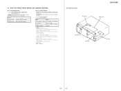
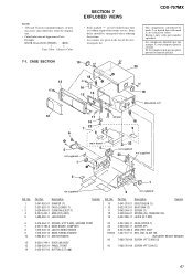
... RES, VAR, SLIDE 10K (ELEVATOR HEIGHT SENSOR) 7-685-792-09 SCREW +PTT 2.6X6 (S) #3 7-685-781-09 SCREW +PTT 2X4 (S) 9 CDX-757MX • EXPLODED VIEWS NOTE: • -XX and -X mean standardized parts, so they may have some difference from the original one. • Color Indication of Appearance... Cabinet's Color • Items marked "*" are not stocked since they are given in the last of the electrical parts list. No. 15 * 16 17 18 19 Part No. Some delay should be anticipated when ordering these items. • Accessories are seldom required for routine service. ...
... RES, VAR, SLIDE 10K (ELEVATOR HEIGHT SENSOR) 7-685-792-09 SCREW +PTT 2.6X6 (S) #3 7-685-781-09 SCREW +PTT 2X4 (S) 9 CDX-757MX • EXPLODED VIEWS NOTE: • -XX and -X mean standardized parts, so they may have some difference from the original one. • Color Indication of Appearance... Cabinet's Color • Items marked "*" are not stocked since they are given in the last of the electrical parts list. No. 15 * 16 17 18 19 Part No. Some delay should be anticipated when ordering these items. • Accessories are seldom required for routine service. ...
Service Manual
Page 59
...181;PB. . uPD. . : µPD. . • CAPACITORS uF: µF • COILS uH: µH When indicating parts by reference number, please include the board. Part No. C113 C114 Part No. Description 1-684-650-12 JACK BOARD *********** Remark Ref. No. uPC. . : µPC. . Ref. Some delay should ...20% 16V 25V 20% 16V 20% 16V 5% 50V C412 1-162-927-11 CERAMIC CHIP 100PF 5% 50V 10 No. CDX-757MX JACK MAIN • ELECTRICAL PARTS LIST NOTE: • Due to standardization, replacements in ohms. METAL: Metal-film resistor. METAL OXIDE: Metal oxide-film resistor...
...181;PB. . uPD. . : µPD. . • CAPACITORS uF: µF • COILS uH: µH When indicating parts by reference number, please include the board. Part No. C113 C114 Part No. Description 1-684-650-12 JACK BOARD *********** Remark Ref. No. uPC. . : µPC. . Ref. Some delay should ...20% 16V 25V 20% 16V 20% 16V 5% 50V C412 1-162-927-11 CERAMIC CHIP 100PF 5% 50V 10 No. CDX-757MX JACK MAIN • ELECTRICAL PARTS LIST NOTE: • Due to standardization, replacements in ohms. METAL: Metal-film resistor. METAL OXIDE: Metal oxide-film resistor...


