Service Manual
Page 1
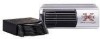
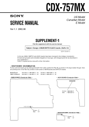
... loading or ejecting a disc) Operating temperature -10°C to +55°C (14°F to change without notice. 9-873-618-02 2002H0500-1 C 2002.08 Sony Corporation e Vehicle Company Published by Sony Engineering Corporation COMPACT DISC CHANGER SERVICE MANUAL Ver 1.1 2002.08 CDX-757MX US Model Canadian Model E Model Model Name Using Similar Mechanism CD Drive Mechanism Type Optical Pick-up Name CDX-747X MG-251B-137 KSS-720A SPECIFICATIONS System Compact disc digital audio system Laser...
... loading or ejecting a disc) Operating temperature -10°C to +55°C (14°F to change without notice. 9-873-618-02 2002H0500-1 C 2002.08 Sony Corporation e Vehicle Company Published by Sony Engineering Corporation COMPACT DISC CHANGER SERVICE MANUAL Ver 1.1 2002.08 CDX-757MX US Model Canadian Model E Model Model Name Using Similar Mechanism CD Drive Mechanism Type Optical Pick-up Name CDX-747X MG-251B-137 KSS-720A SPECIFICATIONS System Compact disc digital audio system Laser...
Service Manual
Page 2
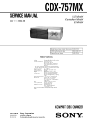
... CRITIQUES POUR LA SÉCURITÉ DE FONCTIONNEMENT. DISC MAGAZINE GETTING OUT PROCEDURE ON THE POWER SUPPLY IS OFF Remove the CASE (LOWER. aged by the charged electrostatic load, etc. REPLACE THESE COMPONENTS WITH SONY PARTS WHOSE PART NUMBERS APPEAR AS SHOWN IN THIS MANUAL OR IN SUPPLEMENTS PUBLISHED BY SONY. NOTES ON LASER DIODE EMISSION CHECK The laser beam...
... CRITIQUES POUR LA SÉCURITÉ DE FONCTIONNEMENT. DISC MAGAZINE GETTING OUT PROCEDURE ON THE POWER SUPPLY IS OFF Remove the CASE (LOWER. aged by the charged electrostatic load, etc. REPLACE THESE COMPONENTS WITH SONY PARTS WHOSE PART NUMBERS APPEAR AS SHOWN IN THIS MANUAL OR IN SUPPLEMENTS PUBLISHED BY SONY. NOTES ON LASER DIODE EMISSION CHECK The laser beam...
Service Manual
Page 3
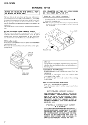
... the CDs. We recommend that supports MP3 is played back with each disc. • Depending on the recording method, it is a standard technology and format for the master unit. When an MP3 file is not displayed accurately during fast-forward/reverse. CDX-757MX TEST DISC This set , use the following cases, elapsed playing time may not be written. * "RealJukebox is played. - Notes on discs You...
... the CDs. We recommend that supports MP3 is played back with each disc. • Depending on the recording method, it is a standard technology and format for the master unit. When an MP3 file is not displayed accurately during fast-forward/reverse. CDX-757MX TEST DISC This set , use the following cases, elapsed playing time may not be written. * "RealJukebox is played. - Notes on discs You...
Service Manual
Page 4
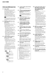
... a CD-R/ RW cannot be displayed. The unit reads the disc information (the number of folders and files, or the location of the data) before playback of 80 minutes running time (700 MB data capacity). The unit supports a disk of MP3 file. Q7 Can the unit play a Multi Session disc? For details, refer to the instruction manual for compressing audio parts of MP3 files? The unit is not output...
... a CD-R/ RW cannot be displayed. The unit reads the disc information (the number of folders and files, or the location of the data) before playback of 80 minutes running time (700 MB data capacity). The unit supports a disk of MP3 file. Q7 Can the unit play a Multi Session disc? For details, refer to the instruction manual for compressing audio parts of MP3 files? The unit is not output...
Service Manual
Page 5
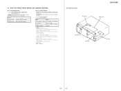
... 2-7. Chassis (U.S) Sub Assy 12 2-9. MECHANICAL ADJUSTMENT 17 5. Schematic Diagram - MAIN (2/3)/SWITCH Boards 29 6-11. JACK Board 32 6-13. LSW Board, Spindle Motor (S) Sub Assy (M102) ........ 14 2-13. SERVO Section 20 6-2. Printed Wiring Boards - Printed Wiring Boards - GENERAL Installation 6 Connections 7 2. Case (Upper. T), Front Panel Assy 9 2-3. JACK Board 10 2-5. Block Diagram - MAIN Board (Component Side 26 6-8. Printed Wiring Boards - IC Pin Function Description 39 7. Mechanism Deck Section-2 (MG...
... 2-7. Chassis (U.S) Sub Assy 12 2-9. MECHANICAL ADJUSTMENT 17 5. Schematic Diagram - MAIN (2/3)/SWITCH Boards 29 6-11. JACK Board 32 6-13. LSW Board, Spindle Motor (S) Sub Assy (M102) ........ 14 2-13. SERVO Section 20 6-2. Printed Wiring Boards - Printed Wiring Boards - GENERAL Installation 6 Connections 7 2. Case (Upper. T), Front Panel Assy 9 2-3. JACK Board 10 2-5. Block Diagram - MAIN Board (Component Side 26 6-8. Printed Wiring Boards - IC Pin Function Description 39 7. Mechanism Deck Section-2 (MG...
Service Manual
Page 17
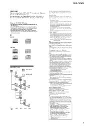
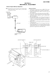
.... 5. At this time, if the elevator shaft does not position between comb teeth A and B. 6. Press repeatedly the DISC + and - After adjustment at addresses 5 to 6 is necessary when the system controller (IC201), variable resistor (RV201), slider (R), slider (L), or chassis (ELV) was replaced for any repair. Connection: power supply (DC 14.4 V) + GND master unit BUS cable Adjustment Method: 1. Connect this time, adjust RV201 on the master unit and select DISC 5. 4.
.... 5. At this time, if the elevator shaft does not position between comb teeth A and B. 6. Press repeatedly the DISC + and - After adjustment at addresses 5 to 6 is necessary when the system controller (IC201), variable resistor (RV201), slider (R), slider (L), or chassis (ELV) was replaced for any repair. Connection: power supply (DC 14.4 V) + GND master unit BUS cable Adjustment Method: 1. Connect this time, adjust RV201 on the master unit and select DISC 5. 4.
Service Manual
Page 18
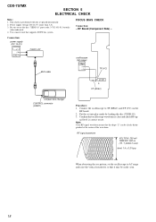
Connection: power supply (DC 14.4 V) + GND master unit oscilloscope (AC range) BUS cable + - Use a master unit that oscilloscope waveform is correct or not. TP (VC) IC101 TP (RFAC) compact disc changer CONTROL connector (CN901) Procedure: 1. This check is performed with the set into play mode by loading the disc (YEDS-18). 3. FOCUS BIAS CHECK Connection: - Connect the oscilloscope to AC range and raise the vertical sensitivity so that the...
Connection: power supply (DC 14.4 V) + GND master unit oscilloscope (AC range) BUS cable + - Use a master unit that oscilloscope waveform is correct or not. TP (VC) IC101 TP (RFAC) compact disc changer CONTROL connector (CN901) Procedure: 1. This check is performed with the set into play mode by loading the disc (YEDS-18). 3. FOCUS BIAS CHECK Connection: - Connect the oscilloscope to AC range and raise the vertical sensitivity so that the...
Service Manual
Page 20
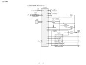
... 74 ASYO 8C DC OFST 30 RF AMP OFFSET CONTROL SWITCH 9D FOCUS ERROR RW/ROM FE 16 FE Q102 AMP D0 - BLOCK DIAGRAM - SERVO Section - MCOOTIOLR DRIVE 25 VIN3 - 24 VO4 + VIN4 + 6 7 VO4 - COIL DRIVE 31 VIN4 - 32 M101 M (SLED) 10 VO2 + VO2 - 11 MOTOR DRIVE VIN2 + 22 VIN2 - 21 TFDR... of the disc chucking operation SW1 (CHUCKING END DETECT) ON : When completion of the disc save operation SW2 (SAVE END DETECT) DIGITAL OUT DOUT 185 PCMDI DAC 1859 PCMD 1858 SELECTOR BCK 1950 LRCK 1856 CLOCK XTAI 1953 GENERATOR XTAO 1954 X101 16.9344MHz CD-ROM/RW SELECT SWITCH Q202 D201 90...
... 74 ASYO 8C DC OFST 30 RF AMP OFFSET CONTROL SWITCH 9D FOCUS ERROR RW/ROM FE 16 FE Q102 AMP D0 - BLOCK DIAGRAM - SERVO Section - MCOOTIOLR DRIVE 25 VIN3 - 24 VO4 + VIN4 + 6 7 VO4 - COIL DRIVE 31 VIN4 - 32 M101 M (SLED) 10 VO2 + VO2 - 11 MOTOR DRIVE VIN2 + 22 VIN2 - 21 TFDR... of the disc chucking operation SW1 (CHUCKING END DETECT) ON : When completion of the disc save operation SW2 (SAVE END DETECT) DIGITAL OUT DOUT 185 PCMDI DAC 1859 PCMD 1858 SELECTOR BCK 1950 LRCK 1856 CLOCK XTAI 1953 GENERATOR XTAO 1954 X101 16.9344MHz CD-ROM/RW SELECT SWITCH Q202 D201 90...
Service Manual
Page 22
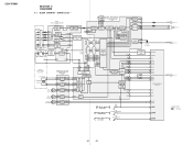
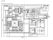
..., 302 +2.5V REGULATOR IC603 SW801 D306 SERVO +3.3V +3.3V REGULATOR IC306 SERVO +5V RESET SIGNAL GENERATOR IC303 BUS INTERFACE (FOR SONY BUS) IC302 VCC 14 SO 10 9 SI 11 SCK 1 BUSON OUT BUSON OUT 13 DATA 6 CLK 4 LOF 12 BUSON IN 2 8 RESET RESET SWITCH RST 7 B. UP +3.3V +5V REGULATOR IC305 +3.3V REGULATOR Q303, 304 CN901 (2/2) CONTROL PS901 7 B. BLOCK DIAGRAM - CDX-757MX 6-3.
..., 302 +2.5V REGULATOR IC603 SW801 D306 SERVO +3.3V +3.3V REGULATOR IC306 SERVO +5V RESET SIGNAL GENERATOR IC303 BUS INTERFACE (FOR SONY BUS) IC302 VCC 14 SO 10 9 SI 11 SCK 1 BUSON OUT BUSON OUT 13 DATA 6 CLK 4 LOF 12 BUSON IN 2 8 RESET RESET SWITCH RST 7 B. UP +3.3V +5V REGULATOR IC305 +3.3V REGULATOR Q303, 304 CN901 (2/2) CONTROL PS901 7 B. BLOCK DIAGRAM - CDX-757MX 6-3.
Service Manual
Page 23
.... • C : panel designation. Note on Schematic Diagram: • All capacitors are taken with a VOM (Input impedance 10 MΩ). pF: µµF 50 WV or less are not indicated except for electrolytics and tantalums. • All resistors are indicated. no mark : CD PLAY ∗ : Impossible to ground in CD play conditions. Replace only with mark 0 are critical for repair. • Power voltage...
.... • C : panel designation. Note on Schematic Diagram: • All capacitors are taken with a VOM (Input impedance 10 MΩ). pF: µµF 50 WV or less are not indicated except for electrolytics and tantalums. • All resistors are indicated. no mark : CD PLAY ∗ : Impossible to ground in CD play conditions. Replace only with mark 0 are critical for repair. • Power voltage...
Service Manual
Page 29
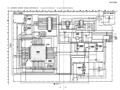
...Diagrams. A1 R115 100 A2 (2/3) G GATE SWITCH V IC605 TC7SH08FU -TE85R V GATE SWITCH...EJECT REV FWD C301 0.1 IC301 LB1930M-TLM ELEVATOR MOTOR DRIVE C302 C303 0.1 0.1 RST SO SI SCK BUSON IC302 BA8272AFV-E2 RESET RST SI DATA SO VREF SCK CLK LOF GND BUSON BUSON IN OUT VCC BUSON OUT BUS INTERFACE (FOR SONY BUS...MUTE CDON CDX-757MX 6-10. TP304 ELV+ TP802 TP801 M104 (ELEVATOR) (CHASSIS) BUCHK Q302 DTA115EKA-T146 R304 1M Q301 MSD601-RT1 Q301,302 BATTERY CHECK R303 100k R305 100k RESET... R413 100 Q402 MUN2111T1 MUTING CONTROL SWITCH LOW-PASS FILTER IC401 ...
...Diagrams. A1 R115 100 A2 (2/3) G GATE SWITCH V IC605 TC7SH08FU -TE85R V GATE SWITCH...EJECT REV FWD C301 0.1 IC301 LB1930M-TLM ELEVATOR MOTOR DRIVE C302 C303 0.1 0.1 RST SO SI SCK BUSON IC302 BA8272AFV-E2 RESET RST SI DATA SO VREF SCK CLK LOF GND BUSON BUSON IN OUT VCC BUSON OUT BUS INTERFACE (FOR SONY BUS...MUTE CDON CDX-757MX 6-10. TP304 ELV+ TP802 TP801 M104 (ELEVATOR) (CHASSIS) BUCHK Q302 DTA115EKA-T146 R304 1M Q301 MSD601-RT1 Q301,302 BATTERY CHECK R303 100k R305 100k RESET... R413 100 Q402 MUN2111T1 MUTING CONTROL SWITCH LOW-PASS FILTER IC401 ...
Service Manual
Page 30
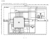
CDX-757MX 6-11. MAIN Board (3/3) - • See page 31 for for Waveforms. • See page 34 for IC Block Diagram. (3/3) B1 (Page 28) TC-XRDE D201 M1MA152WK-T1 R202 100k XRDE C201 ...ML MC MD XWRE (FOR PC) CN201 6P RESET PCTX PCRX FL_BOOT +B GND TP210 TP209 TP208 TP207 R211 100k R206 100k R201 100k MUTE CDON EVON FWD REV SCOR GRSCOR MUTE NC NC CDON EVON PCTX PCRX NC NC ... R208 100k SW201 MAGAZINE DETECT LIM SAVE LOAD REV FWD BUCHK BUSON BP201 R215 1k Q202 MUN2211T1 CD-ROM/ RW SELECT SWITCH SQCK SQSO SCL SDA SCK SI SO R212 R210 1k 10k DECINT IC202 BR24C16FJ-E2 SDA SCL...
CDX-757MX 6-11. MAIN Board (3/3) - • See page 31 for for Waveforms. • See page 34 for IC Block Diagram. (3/3) B1 (Page 28) TC-XRDE D201 M1MA152WK-T1 R202 100k XRDE C201 ...ML MC MD XWRE (FOR PC) CN201 6P RESET PCTX PCRX FL_BOOT +B GND TP210 TP209 TP208 TP207 R211 100k R206 100k R201 100k MUTE CDON EVON FWD REV SCOR GRSCOR MUTE NC NC CDON EVON PCTX PCRX NC NC ... R208 100k SW201 MAGAZINE DETECT LIM SAVE LOAD REV FWD BUCHK BUSON BP201 R215 1k Q202 MUN2211T1 CD-ROM/ RW SELECT SWITCH SQCK SQSO SCL SDA SCK SI SO R212 R210 1k 10k DECINT IC202 BR24C16FJ-E2 SDA SCL...
Service Manual
Page 39
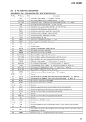
... used I Magazine detect switch input terminal Not used O Audio line muting on/off control signal output "H": muting on O Not used O D/A convert and servo sections power supply on/off control signal output "H": power on O Mechanism deck section power supply on/off control signal output "H": power on O PC connecting output terminal for UART I PC connecting input terminal for UART O Not used O Motor drive signal (elevator up direction) output to the elevator motor drive O Motor drive signal (elevator down direction) output to the DSP "L": reset - Pin...
... used I Magazine detect switch input terminal Not used O Audio line muting on/off control signal output "H": muting on O Not used O D/A convert and servo sections power supply on/off control signal output "H": power on O Mechanism deck section power supply on/off control signal output "H": power on O PC connecting output terminal for UART I PC connecting input terminal for UART O Not used O Motor drive signal (elevator up direction) output to the elevator motor drive O Motor drive signal (elevator down direction) output to the DSP "L": reset - Pin...
Service Manual
Page 40
... changes to "H" O Not used (fixed at "H") O Standby mode control signal output terminal Not used (fixed at "H" in this set) I Chucking end detect switch input terminal "L": When completion of the disc chucking operation I Save end detect switch input terminal "L": When completion of the disc save direction) output to the chucking motor drive I System reset signal input from the SONY bus interface and reset signal generator "L": reset For several hundreds msec. Power supply terminal (+3.3V) I /O Description - CDX-757MX Pin...
... changes to "H" O Not used (fixed at "H") O Standby mode control signal output terminal Not used (fixed at "H" in this set) I Chucking end detect switch input terminal "L": When completion of the disc chucking operation I Save end detect switch input terminal "L": When completion of the disc save direction) output to the chucking motor drive I System reset signal input from the SONY bus interface and reset signal generator "L": reset For several hundreds msec. Power supply terminal (+3.3V) I /O Description - CDX-757MX Pin...
Service Manual
Page 46
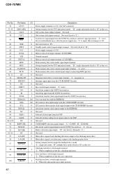
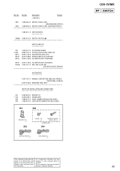
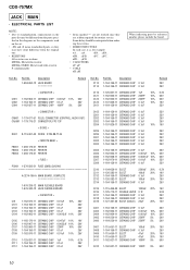
... by reference number, please include the board. When indicating parts by mark 0 or dotted line with part number specified. ...077-51 PLUG, CONNECTOR (CONTROL, AUDIO OUT) CNJ901 1-778-775-21 CONNECTOR, FPC...LSW BOARD ********** < SWITCH > SW3 1-529-565-41 SWITCH, PUSH (1 KEY...CDX-757MX JACK LSW MAIN SECTION 8 ELECTRICAL PARTS LIST NOTE: • Due to standardization, replacements in the parts list may have some difference from the parts specified in the diagrams or the components used on the set. • -XX and -X mean standardized parts, so they are seldom required for routine service...
... by reference number, please include the board. When indicating parts by mark 0 or dotted line with part number specified. ...077-51 PLUG, CONNECTOR (CONTROL, AUDIO OUT) CNJ901 1-778-775-21 CONNECTOR, FPC...LSW BOARD ********** < SWITCH > SW3 1-529-565-41 SWITCH, PUSH (1 KEY...CDX-757MX JACK LSW MAIN SECTION 8 ELECTRICAL PARTS LIST NOTE: • Due to standardization, replacements in the parts list may have some difference from the parts specified in the diagrams or the components used on the set. • -XX and -X mean standardized parts, so they are seldom required for routine service...
Service Manual
Page 49
... 10K (ELEVATOR HEIGHT SENSOR ACCESSORIES 3-241-142-11 MANUAL, INSRTUCTION (ENGLISH, FRENCH, TRADITIONAL CHINESE) A-3301-944-A MAGAZINE (250) ASSY PARTS FOR INSTALLATION AND CONNECTIONS 501 * 502 503 504 3-040-583-21 BRACKET (T) X-3369-824-1 SCREW ASSY 1-590-874-11 CORD, CONNECTION (RCA PIN CORD) 1-590-519-21 CORD (WITH CONNECTOR) (BUS CABLE) Description CDX-757MX RF SWITCH Remark 501 502 BRACKET (T) × 2 503 +PSW4 ×...
... 10K (ELEVATOR HEIGHT SENSOR ACCESSORIES 3-241-142-11 MANUAL, INSRTUCTION (ENGLISH, FRENCH, TRADITIONAL CHINESE) A-3301-944-A MAGAZINE (250) ASSY PARTS FOR INSTALLATION AND CONNECTIONS 501 * 502 503 504 3-040-583-21 BRACKET (T) X-3369-824-1 SCREW ASSY 1-590-874-11 CORD, CONNECTION (RCA PIN CORD) 1-590-519-21 CORD (WITH CONNECTOR) (BUS CABLE) Description CDX-757MX RF SWITCH Remark 501 502 BRACKET (T) × 2 503 +PSW4 ×...
Service Manual
Page 50
... - Printed wiring boards and schematic diagrams of MAIN boards and SWITCH boards. JACK BOARD (Conductor Side) - as shown in the figure below though, there are described in this supplement-1. SERVICE MANUAL Ver 1.1 2002.08 CDX-757MX US Model Canadian Model E Model SUPPLEMENT-1 File this supplement with their suffix number the Part No. printed on silk-screen of new type, and changed in the Part No. MAIN...
... - Printed wiring boards and schematic diagrams of MAIN boards and SWITCH boards. JACK BOARD (Conductor Side) - as shown in the figure below though, there are described in this supplement-1. SERVICE MANUAL Ver 1.1 2002.08 CDX-757MX US Model Canadian Model E Model SUPPLEMENT-1 File this supplement with their suffix number the Part No. printed on silk-screen of new type, and changed in the Part No. MAIN...
Service Manual
Page 51
... dc power supply from CD changer controller. • Voltages and waveforms are dc with respect to ground in µF unless otherwise noted. Voltage variations may be noted due to normal production tolerances. • Circled numbers refer to normal production tolerances. • Waveforms are taken with a VOM (Input impedance 10 MΩ). CDX-757MX • DIAGRAMS NOTE FOR PRINTED WIRING BOARDS AND SCHEMATIC DIAGRAMS...
... dc power supply from CD changer controller. • Voltages and waveforms are dc with respect to ground in µF unless otherwise noted. Voltage variations may be noted due to normal production tolerances. • Circled numbers refer to normal production tolerances. • Waveforms are taken with a VOM (Input impedance 10 MΩ). CDX-757MX • DIAGRAMS NOTE FOR PRINTED WIRING BOARDS AND SCHEMATIC DIAGRAMS...
Service Manual
Page 53
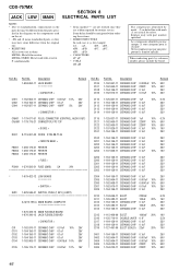
... R304 1M Q301 MSD601-RT1 Q301,302 BATTERY CHECK R303 100k R305 100k RESET SIGNAL GENERATOR IC303 XC61CN2702NR VOUT GND VIN NC... C9 D302 MM3Z18VST1 C305 0.001 MUTE CDON CDX-757MX SCHEMATIC DIAGRAM - MAIN (2/3)/SWITCH Boards - A1 R115 100 A2 (2/3) G GATE SWITCH V IC605 TC7SH08FU -TE85R V GATE SWITCH G IC604 TC7SH08FU -TE85R A11 ...EJECT REV FWD C301 0.1 IC301 LB1930M-TLM ELEVATOR MOTOR DRIVE C302 C303 0.1 0.1 RST SO SI SCK BUSON IC302 BA8272AFV-E2 RESET RST SI DATA SO VREF SCK CLK LOF GND BUSON BUSON IN OUT VCC BUSON OUT BUS INTERFACE (FOR SONY BUS...
... R304 1M Q301 MSD601-RT1 Q301,302 BATTERY CHECK R303 100k R305 100k RESET SIGNAL GENERATOR IC303 XC61CN2702NR VOUT GND VIN NC... C9 D302 MM3Z18VST1 C305 0.001 MUTE CDON CDX-757MX SCHEMATIC DIAGRAM - MAIN (2/3)/SWITCH Boards - A1 R115 100 A2 (2/3) G GATE SWITCH V IC605 TC7SH08FU -TE85R V GATE SWITCH G IC604 TC7SH08FU -TE85R A11 ...EJECT REV FWD C301 0.1 IC301 LB1930M-TLM ELEVATOR MOTOR DRIVE C302 C303 0.1 0.1 RST SO SI SCK BUSON IC302 BA8272AFV-E2 RESET RST SI DATA SO VREF SCK CLK LOF GND BUSON BUSON IN OUT VCC BUSON OUT BUS INTERFACE (FOR SONY BUS...
Service Manual
Page 59
... µ, for routine service. No. CDX-757MX JACK MAIN • ELECTRICAL PARTS LIST NOTE: • Due to standardization, replacements in the parts list may have some difference from the parts specified in the diagrams or the components used on the set. • -XX and -X mean standardized parts, so they are in ...077-51 PLUG, CONNECTOR (CONTROL, AUDIO OUT) CNJ901 1-778-775-21 CONNECTOR, FPC 13P < DIODE > D901 8-719-067-40 DIODE STZ6.8N-T146 < FERRITE BEAD > FB901 FB902 FB903 1-469-179-21 FERRITE 1-469-179-21 FERRITE 1-469-179-21 FERRITE < FUSE > PS901 1-576-592-21 FUSE (SMD...
... µ, for routine service. No. CDX-757MX JACK MAIN • ELECTRICAL PARTS LIST NOTE: • Due to standardization, replacements in the parts list may have some difference from the parts specified in the diagrams or the components used on the set. • -XX and -X mean standardized parts, so they are in ...077-51 PLUG, CONNECTOR (CONTROL, AUDIO OUT) CNJ901 1-778-775-21 CONNECTOR, FPC 13P < DIODE > D901 8-719-067-40 DIODE STZ6.8N-T146 < FERRITE BEAD > FB901 FB902 FB903 1-469-179-21 FERRITE 1-469-179-21 FERRITE 1-469-179-21 FERRITE < FUSE > PS901 1-576-592-21 FUSE (SMD...


