
Service Manual
Page 1
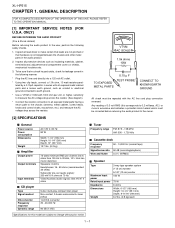
S4422XLHP515U MICRO COMPONENT SYSTEM MODEL XL-HP515 XL-HP515 Micro Component System consisting of XLHP515 (main unit) and CP-HP515 (speaker system). • In the interests of Stereo System Error Message Display Contents 2-5 CHAPTER 3. ADJUSTMENTS [1] ADJUSTMENT 2-1 [2] TEST MODE 2-3 [3] Standard Specification of user-safety the set should be restored to its original condition and only parts identical to change without notice. CONTENTS CHAPTER 1. The contents are subject to those specified be used . MECHANICAL DESCRIPTION...
S4422XLHP515U MICRO COMPONENT SYSTEM MODEL XL-HP515 XL-HP515 Micro Component System consisting of XLHP515 (main unit) and CP-HP515 (speaker system). • In the interests of Stereo System Error Message Display Contents 2-5 CHAPTER 3. ADJUSTMENTS [1] ADJUSTMENT 2-1 [2] TEST MODE 2-3 [3] Standard Specification of user-safety the set should be restored to its original condition and only parts identical to change without notice. CONTENTS CHAPTER 1. The contents are subject to those specified be used . MECHANICAL DESCRIPTION...
Service Manual
Page 2
... following manner. * Plug the AC line cord directly into 6 ohms from 100 Hz to 20 kHz, 10% total harmonic distortion Speakers: 6 ohms Headphones: 16 - 50 ohms (recommended: 32 ohms) Subwoofer pre-out (audio signal): 200 mV/10 k ohms at 70 Hz Video/Auxiliary (audio signal): 500 mV/47 k ohms 5-disc multi-play compact disc player Non-contact, 3-beam semiconductor laser pickup 1-bit D/A converter 20 - 20,000 Hz 90 dB (1 kHz) I Tuner Frequency range FM: 87.5 - 108...
... following manner. * Plug the AC line cord directly into 6 ohms from 100 Hz to 20 kHz, 10% total harmonic distortion Speakers: 6 ohms Headphones: 16 - 50 ohms (recommended: 32 ohms) Subwoofer pre-out (audio signal): 200 mV/10 k ohms at 70 Hz Video/Auxiliary (audio signal): 500 mV/47 k ohms 5-disc multi-play compact disc player Non-contact, 3-beam semiconductor laser pickup 1-bit D/A converter 20 - 20,000 Hz 90 dB (1 kHz) I Tuner Frequency range FM: 87.5 - 108...
Service Manual
Page 3
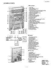
... Play Button 7. Volume Control 15. Extra Bass/Demo Mode Button 19. FM Stereo Mode Indicator 12. Cooling Fan 2. Video/Auxiliary (Audio Signal) Input Jacks 8. Woofer 3. Power On/Stand-by Button 4. Headphone Jack 10. Memory/Set Button 17. CD Indicator 7. Sleep Indicator 16. FM 75 Ohms Antenna Terminal 5. Bass Reflex Duct 1 3 4. CD Track Up or Fast Forward, Tape Fast Wind, Tuner Preset Up, Time Up Button 16. Tape Button 24. CD or Tape Stop Button 21. CD Play Indicator 3. Tape Forward Play Indicator 10. Subwoofer Pre-output Jack ■ Speaker...
... Play Button 7. Volume Control 15. Extra Bass/Demo Mode Button 19. FM Stereo Mode Indicator 12. Cooling Fan 2. Video/Auxiliary (Audio Signal) Input Jacks 8. Woofer 3. Power On/Stand-by Button 4. Headphone Jack 10. Memory/Set Button 17. CD Indicator 7. Sleep Indicator 16. FM 75 Ohms Antenna Terminal 5. Bass Reflex Duct 1 3 4. CD Track Up or Fast Forward, Tape Fast Wind, Tuner Preset Up, Time Up Button 16. Tape Button 24. CD or Tape Stop Button 21. CD Play Indicator 3. Tape Forward Play Indicator 10. Subwoofer Pre-output Jack ■ Speaker...
Service Manual
Page 4
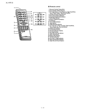
... Play Button 19. Disc Direct Search Buttons 21 6. Clock/Timer Button 15. CD Play or Repeat Button 23. Equalizer Mode Select Button 7. Video/Auxiliary Button 13. CD Pause Button 22. CD Track Down or Fast Reverse, Tape Fast Wind, Tuner Preset Down, Time Down Button 20 4. Volume Up and Down Buttons 5. Disc Number Select Buttons 3. Tuner (Band) Button 24 11. Extra Bass Button 22 8. Tape Record Pause Button 1 - 3 XL-HP515 1 2 3 4 5 6 7 8 9 10 15 16 11 17 12 18 13 19 14 I Remote control 1. Remote Control Transmitter 2. Tape Button 12. Memory/Set Button...
... Play Button 19. Disc Direct Search Buttons 21 6. Clock/Timer Button 15. CD Play or Repeat Button 23. Equalizer Mode Select Button 7. Video/Auxiliary Button 13. CD Pause Button 22. CD Track Down or Fast Reverse, Tape Fast Wind, Tuner Preset Down, Time Down Button 20 4. Volume Up and Down Buttons 5. Disc Number Select Buttons 3. Tuner (Band) Button 24 11. Extra Bass Button 22 8. Tape Record Pause Button 1 - 3 XL-HP515 1 2 3 4 5 6 7 8 9 10 15 16 11 17 12 18 13 19 14 I Remote control 1. Remote Control Transmitter 2. Tape Button 12. Memory/Set Button...
Service Manual
Page 5
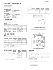
... head amplifier output and the VREF reference voltage is not needed when replacing the pickup. AXSMECeLuaHrdH-vrHkiAioPcePe5tP51M1T55aEnuRal2. Each time a disc is changed, these adjustments are performed automatically. Specified Value 3,000 ± 30 Hz Instrument Connection Speaker Terminal (Load resistance: 6 ohms) TAPE MECHANISM Tape Motor Variable Resistor in motor. TUNER SECTION fL: Low-range frequency fH: High-range frequency • AM IF/RF Signal generator: 400 Hz, 30%, AM modulated Test...
... head amplifier output and the VREF reference voltage is not needed when replacing the pickup. AXSMECeLuaHrdH-vrHkiAioPcePe5tP51M1T55aEnuRal2. Each time a disc is changed, these adjustments are performed automatically. Specified Value 3,000 ± 30 Hz Instrument Connection Speaker Terminal (Load resistance: 6 ohms) TAPE MECHANISM Tape Motor Variable Resistor in motor. TUNER SECTION fL: Low-range frequency fH: High-range frequency • AM IF/RF Signal generator: 400 Hz, 30%, AM modulated Test...

Service Manual
Page 6
... cam operation error during initialize process. CAM error. CD ERROR CODE DESCRIPTION Error 01 10* 11* 20* 21* 31 Explanation When Pickup set inner position, inner switch cannot detect 'ON' level for the 5th times. 2 - 2 Can't detect CAM switch when CAM is moving . TRAY error. XL-HP515 2) Tracking balance adjustment 3) Gain adjustment (The gain is compensated inside the IC so that the loop gain at the gain crossover frequency...
... cam operation error during initialize process. CAM error. CD ERROR CODE DESCRIPTION Error 01 10* 11* 20* 21* 31 Explanation When Pickup set inner position, inner switch cannot detect 'ON' level for the 5th times. 2 - 2 Can't detect CAM switch when CAM is moving . TRAY error. XL-HP515 2) Tracking balance adjustment 3) Gain adjustment (The gain is compensated inside the IC so that the loop gain at the gain crossover frequency...
Service Manual
Page 7
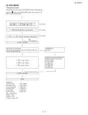
CD T EST OPEN/CLOSE operation is input into PLAY key, track number can be appoint directly. IL isn't done A to enter the test mode. When these following key is using manual. STOP explanation: a) Focus off set = "FOF_XXXX" b)Tracking off set = "TOF_XXXX" c)Tracking balance = "TBAL_XX" d)Tracking Gain = "TGAN_XX" f) Focus Gain = "FGAN_XX" g) RF level shift = "RFLS_XX" VOL - XL-HP515 2 - 3 IL isn't done IL isn't done >,>buttons make pick's slide...
CD T EST OPEN/CLOSE operation is input into PLAY key, track number can be appoint directly. IL isn't done A to enter the test mode. When these following key is using manual. STOP explanation: a) Focus off set = "FOF_XXXX" b)Tracking off set = "TOF_XXXX" c)Tracking balance = "TBAL_XX" d)Tracking Gain = "TGAN_XX" f) Focus Gain = "FGAN_XX" g) RF level shift = "RFLS_XX" VOL - XL-HP515 2 - 3 IL isn't done IL isn't done >,>buttons make pick's slide...
Service Manual
Page 8
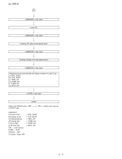
STOP Sliding the PICKUP with>, > button must only be 2 - 4 key input. Adjustment result automatically will display as below for each 2 sec : a) "FOF_XXXX" b) "TOF_XXXX" c) "TBAL_XX" d) "TGAN_XX" f) "FGAN_XX" g) "RFLS_XX" key input. key input. key input. XL-HP515 A key input. Tracking ON play at that specific point. Tracking OFF play from that specific point. Laser ON.
STOP Sliding the PICKUP with>, > button must only be 2 - 4 key input. Adjustment result automatically will display as below for each 2 sec : a) "FOF_XXXX" b) "TOF_XXXX" c) "TBAL_XX" d) "TGAN_XX" f) "FGAN_XX" g) "RFLS_XX" key input. key input. key input. XL-HP515 A key input. Tracking ON play at that specific point. Tracking OFF play from that specific point. Laser ON.
Service Manual
Page 9
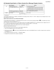
... during version number display and then press 'POWER', 'MEMORY/SET' and 'VIDEO/AUX' button. Micro- Press 'VIDEO/AUX' button during initialize process DSP COMMUNICATION ERROR. Unplug the AC cord and the unit is condition when irregular process occur on power supply line. [3] Standard Specification of 'ER-CD**'. 'ER-CD**' display will only be display when error had occurred, it can be check by mode. 2. Focus Not Match/IL Time Over...
... during version number display and then press 'POWER', 'MEMORY/SET' and 'VIDEO/AUX' button. Micro- Press 'VIDEO/AUX' button during initialize process DSP COMMUNICATION ERROR. Unplug the AC cord and the unit is condition when irregular process occur on power supply line. [3] Standard Specification of 'ER-CD**'. 'ER-CD**' display will only be display when error had occurred, it can be check by mode. 2. Focus Not Match/IL Time Over...
Service Manual
Page 15
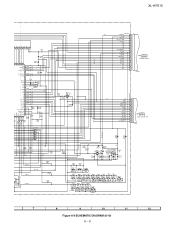
XL-HP515 SYSTEM MUTE VL+ VLñ GND Q603 Q604 _+10V D_+8V 851 12 5 21 FL701 FL DISPLAY 28 31 32 41 +B10 44 45 MOTOR/ SOLENOID DRIVER Q701,702 Q712~715 TAPE MECHANISM ASS'Y +B10 LED701 38 48 69 78 79 VLOAD 36 P_IN 41 SMUTE 42 TIME LED 45 VOL_LED AC_RLY T_SOL T_MOTOR... RL914 RELAY +B3 SO901 SPEAKER TERMINAL JK701 HEADPHONES D801 VLñ IC851 VL+ AN80T53 MULTI REGULATOR D802 F802 4A 125V F801 4A 125V PT801 POWER TRANSFORMER (MAIN) JK953 SUB WOOFER PRE-OUT 67 1 4 3 52 F804 2A 125V F805 4A 125V 10V 8.5V 5.1V GND VCC SW 13V +B3 AC POWER SUPPLY CORD AC 120V,60 Hz VF2...
XL-HP515 SYSTEM MUTE VL+ VLñ GND Q603 Q604 _+10V D_+8V 851 12 5 21 FL701 FL DISPLAY 28 31 32 41 +B10 44 45 MOTOR/ SOLENOID DRIVER Q701,702 Q712~715 TAPE MECHANISM ASS'Y +B10 LED701 38 48 69 78 79 VLOAD 36 P_IN 41 SMUTE 42 TIME LED 45 VOL_LED AC_RLY T_SOL T_MOTOR... RL914 RELAY +B3 SO901 SPEAKER TERMINAL JK701 HEADPHONES D801 VLñ IC851 VL+ AN80T53 MULTI REGULATOR D802 F802 4A 125V F801 4A 125V PT801 POWER TRANSFORMER (MAIN) JK953 SUB WOOFER PRE-OUT 67 1 4 3 52 F804 2A 125V F805 4A 125V 10V 8.5V 5.1V GND VCC SW 13V +B3 AC POWER SUPPLY CORD AC 120V,60 Hz VF2...
Service Manual
Page 19
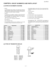
... type (P.P.): Polypropylene type • Schematic diagram and Wiring Side of P.W.Board for maintaining the safety of the set . In the CD section, the CD is being played back. 5. NO SW714 SW715 SW716 SW717 SW718 SW719 SW720 SW721 SW722 SW723 SW724 SW725 SW726 SW727 SW728 DESCRIPTION TUNING/TIME UP TUNING/TIME DOWN STOP PLAY PRESET UP X-BASS/DEMO EQUALIZER MEMORY/SET DIRECT PLAY DISC 1 DISC 2 DISC 3 DISC 4 DISC 5 OPEN/CLOSE POSITION ON-OFF...
... type (P.P.): Polypropylene type • Schematic diagram and Wiring Side of P.W.Board for maintaining the safety of the set . In the CD section, the CD is being played back. 5. NO SW714 SW715 SW716 SW717 SW718 SW719 SW720 SW721 SW722 SW723 SW724 SW725 SW726 SW727 SW728 DESCRIPTION TUNING/TIME UP TUNING/TIME DOWN STOP PLAY PRESET UP X-BASS/DEMO EQUALIZER MEMORY/SET DIRECT PLAY DISC 1 DISC 2 DISC 3 DISC 4 DISC 5 OPEN/CLOSE POSITION ON-OFF...
Service Manual
Page 27
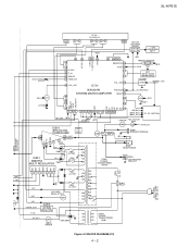
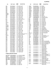
... 26 TUN_SM/SPAN 27 R026 0 C705 0.022 FPA/FPB SW 28 PROTECT 29 VOL_JOG 30 R721 1K R720 1K 6 35 34 33 32 31...RX701 GP1UM271 REMOTE SENSOR 1 2 3 R798 100 C721 47/16 C720 0.022 R797 100K C722 150P(CH) D707 MA111 C718 0.01 RD17 680 RD18 820 SW719 SW720 SW721 X-BASS /DEMO EQUALIZER MEMORY /SET RD08 ...TUNER VIDEO /AUX TAPE (BAND) RD01 RD02 RD03 RD04 680 820 1K 1.5K SW701 SW702 SW703 SW704 TUNING TUNING REC/ /TIME /TIME PAUSE UP DOWN SW705 STOP PRESET PLAY UP ON/ CLOCK/ REVERSE REVERSE STANDBY TIMER/ MODE PLAY PRESET DOWN 7 8 9 10 11 12 Figure 6-9 SCHEMATIC DIAGRAM...
... 26 TUN_SM/SPAN 27 R026 0 C705 0.022 FPA/FPB SW 28 PROTECT 29 VOL_JOG 30 R721 1K R720 1K 6 35 34 33 32 31...RX701 GP1UM271 REMOTE SENSOR 1 2 3 R798 100 C721 47/16 C720 0.022 R797 100K C722 150P(CH) D707 MA111 C718 0.01 RD17 680 RD18 820 SW719 SW720 SW721 X-BASS /DEMO EQUALIZER MEMORY /SET RD08 ...TUNER VIDEO /AUX TAPE (BAND) RD01 RD02 RD03 RD04 680 820 1K 1.5K SW701 SW702 SW703 SW704 TUNING TUNING REC/ /TIME /TIME PAUSE UP DOWN SW705 STOP PRESET PLAY UP ON/ CLOCK/ REVERSE REVERSE STANDBY TIMER/ MODE PLAY PRESET DOWN 7 8 9 10 11 12 Figure 6-9 SCHEMATIC DIAGRAM...
Service Manual
Page 39
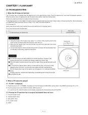
... replace the cleaner disc. All rights reserved. CD optical pickup Lens cleaner disc Parts code UDSKA0004AFZZ HOW TO USE 1. Do not drink the cleaner fluid or allow it . 2. The CD cleaner disc must not be effective for about 20 seconds and the CD player will automatically stop button. "E-CD01" is displayed. 1) Check the power to IC1 (LC78648E), the presence of the clock signal...
... replace the cleaner disc. All rights reserved. CD optical pickup Lens cleaner disc Parts code UDSKA0004AFZZ HOW TO USE 1. Do not drink the cleaner fluid or allow it . 2. The CD cleaner disc must not be effective for about 20 seconds and the CD player will automatically stop button. "E-CD01" is displayed. 1) Check the power to IC1 (LC78648E), the presence of the clock signal...

Service Manual
Page 40
... 0.20 div =Trigger= Mode : AUTO Type : EDGE CH1 Delay : 0.0 ns Hold off : 0.2 µs Figure 1 1. Press the Tray1 CD Eject Button without inserting a disc, and try starting the playback operation. Is the turntable rotating ? Is focus servo activated ? (Waveform drawing Figure 2) Yes 2. XL-HP515 (1) Focus-HF system check. No Spindle motor (M1A). No If the level is generated, DRF will...
... 0.20 div =Trigger= Mode : AUTO Type : EDGE CH1 Delay : 0.0 ns Hold off : 0.2 µs Figure 1 1. Press the Tray1 CD Eject Button without inserting a disc, and try starting the playback operation. Is the turntable rotating ? Is focus servo activated ? (Waveform drawing Figure 2) Yes 2. XL-HP515 (1) Focus-HF system check. No Spindle motor (M1A). No If the level is generated, DRF will...
Service Manual
Page 43
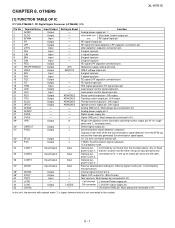
Output Output Output Output Output Input/Output Input/Output Input/Output Input/Output Output Output Input - Setting in Reset ZHI AVDD1/2 - - - - - ADAVDD/2 ADAVDD/2 ADAVDD/2 ADAVDD/2 - - - - Function Analog power supply pin 1. slice level con- RF signal Output pin. VREF voltage output pin. TE signal LPF capacitor connection pin. D/A output. D/A output. Digital power supply pin. C1, C2 error correction monitor pin 7.35kHz Synchronization signal output pin. pose I /O pin 1. General pur- LR channel GND pin. OTHERS XL-HP515 [1] FUNCTION TABLE OF IC...
Output Output Output Output Output Input/Output Input/Output Input/Output Input/Output Output Output Input - Setting in Reset ZHI AVDD1/2 - - - - - ADAVDD/2 ADAVDD/2 ADAVDD/2 ADAVDD/2 - - - - Function Analog power supply pin 1. slice level con- RF signal Output pin. VREF voltage output pin. TE signal LPF capacitor connection pin. D/A output. D/A output. Digital power supply pin. C1, C2 error correction monitor pin 7.35kHz Synchronization signal output pin. pose I /O pin 1. General pur- LR channel GND pin. OTHERS XL-HP515 [1] FUNCTION TABLE OF IC...
Service Manual
Page 44
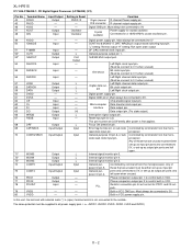
... output mode switching input pin. General-purpose output pin 1. 16.9344 MHz output port. Bit clock output pin. Must always be connected to 0V CONT4 to 0V. Interface Data output pin. Phase comparison output pin 2 to the outside. Built-in VCO GND pin. Digital power supply pin. DAC external clock input pin. Chip enable signal input pin. General-purpose I /O pin 5. Digital power supply pin. Error flag monitor pin, or sub code Controlled...
... output mode switching input pin. General-purpose output pin 1. 16.9344 MHz output port. Bit clock output pin. Must always be connected to 0V CONT4 to 0V. Interface Data output pin. Phase comparison output pin 2 to the outside. Built-in VCO GND pin. Digital power supply pin. DAC external clock input pin. Chip enable signal input pin. General-purpose I /O pin 5. Digital power supply pin. Error flag monitor pin, or sub code Controlled...
Service Manual
Page 59
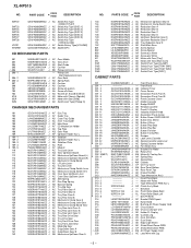
... [PRESET DOWN] AC Switch,Key Type [CD] AC Switch,Key Type [TUNER (BAND)] AC Switch,Key Type [VIDEO/AUX] AC Switch,Key Type [TAPE] AC Switch,Key Type [REC/PAUSE] AC Switch,Key Type [TUNING/TIME UP] AC Switch,Key Type [TUNING/TIME DOWN] AC Switch,Key Type [STOP] AC Switch,Key Type [PLAY] AC Switch,Key Type [PRESET UP] AC Switch,Key Type [X-BASS/DEMO] AC Switch,Key Type [EQUALISER] AC Switch,Key Type [MEMORY/SET] - 4 - PART CODE PRICE...
... [PRESET DOWN] AC Switch,Key Type [CD] AC Switch,Key Type [TUNER (BAND)] AC Switch,Key Type [VIDEO/AUX] AC Switch,Key Type [TAPE] AC Switch,Key Type [REC/PAUSE] AC Switch,Key Type [TUNING/TIME UP] AC Switch,Key Type [TUNING/TIME DOWN] AC Switch,Key Type [STOP] AC Switch,Key Type [PLAY] AC Switch,Key Type [PRESET UP] AC Switch,Key Type [X-BASS/DEMO] AC Switch,Key Type [EQUALISER] AC Switch,Key Type [MEMORY/SET] - 4 - PART CODE PRICE...
Service Manual
Page 60
... Indicator,Timer AC Cover,Sensor AG Decoration Panel,Front A AG Decoration Panel,Front B AG Panel,Cassette Cover AF Holder,Cassette AD Badge,SHARP AB Window,Cassette AD Panel,FL Display AD Indicator,Volume Knob AQ Decoration Panel,Center AE Button,Power ON/STAND-BY AE Button,Disc Select AE Button,X-Bass AF Button,Play/Stop AF Button,Play/Rev AE Button,Function AE Button,Tuning/Rec AD Damper AC Lock Lever,Cassette AB Spring...
... Indicator,Timer AC Cover,Sensor AG Decoration Panel,Front A AG Decoration Panel,Front B AG Panel,Cassette Cover AF Holder,Cassette AD Badge,SHARP AB Window,Cassette AD Panel,FL Display AD Indicator,Volume Knob AQ Decoration Panel,Center AE Button,Power ON/STAND-BY AE Button,Disc Select AE Button,X-Bass AF Button,Play/Stop AF Button,Play/Rev AE Button,Function AE Button,Tuning/Rec AD Damper AC Lock Lever,Cassette AB Spring...
Service Manual
Page 61
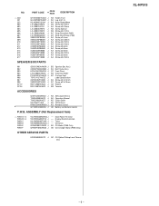
... Loop Antenna AE Operation Manual AD Quick Guide AD FM Antenna AS Remote Control AE Battery Lid,Remote Control P.W.B. ASSEMBLY (Not Replacement Item) 1 PWB-A1~3 PWB-B1~4 PWB-C PWB-D PWB-E PWB-F 92LPWB5609MANS J 92LPWB5609DPLS J 92LPWB5609TUNS J 92LPWB5529CDUS J QPWBF0027AWZZ J QPWBF1055AWZZ J -- CD Servo AD CD Motor (PWB Only) AE CD Changer Motor (PWB Only) OTHER SERVICE PARTS UDSKA0004AFZZ J AZ CD Optical Pickup Lens Cleaner Disc XL-HP515 - 6 - Main/Power/Terminal -- Tuner -- NO...
... Loop Antenna AE Operation Manual AD Quick Guide AD FM Antenna AS Remote Control AE Battery Lid,Remote Control P.W.B. ASSEMBLY (Not Replacement Item) 1 PWB-A1~3 PWB-B1~4 PWB-C PWB-D PWB-E PWB-F 92LPWB5609MANS J 92LPWB5609DPLS J 92LPWB5609TUNS J 92LPWB5529CDUS J QPWBF0027AWZZ J QPWBF1055AWZZ J -- CD Servo AD CD Motor (PWB Only) AE CD Changer Motor (PWB Only) OTHER SERVICE PARTS UDSKA0004AFZZ J AZ CD Optical Pickup Lens Cleaner Disc XL-HP515 - 6 - Main/Power/Terminal -- Tuner -- NO...
Service Manual
Page 66
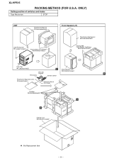
... Tape Mechanism STOP UNIT Polyethylene Bag,Unit SSAKH0094AWZZ Label,Energy Star TLABZA113AWSA Packing Add.,Unit,Left/Right SPAKAA011AWZZ Bottom Front Speaker(L/R) Polyethylene Bag,Speaker SSAKH0099AWZZ Packing,Add., Front Speaker,Top/Bottom SPAKAA015AWZZ Label,Pop TLABZA024AWZZ A Sheet,Speaker AM Loop SPAKZA012AWZZ Antenna B FM Antenna Remote Control Polyethylene Bag,Accessories 92LBAG1460C1 Operation Manual Quic Guide Pad,Add., SPAKZA050AWZZ B A Packing Case SPAKCA114AWZZ : Not Replacement Item - 11 - XL-HP515...
... Tape Mechanism STOP UNIT Polyethylene Bag,Unit SSAKH0094AWZZ Label,Energy Star TLABZA113AWSA Packing Add.,Unit,Left/Right SPAKAA011AWZZ Bottom Front Speaker(L/R) Polyethylene Bag,Speaker SSAKH0099AWZZ Packing,Add., Front Speaker,Top/Bottom SPAKAA015AWZZ Label,Pop TLABZA024AWZZ A Sheet,Speaker AM Loop SPAKZA012AWZZ Antenna B FM Antenna Remote Control Polyethylene Bag,Accessories 92LBAG1460C1 Operation Manual Quic Guide Pad,Add., SPAKZA050AWZZ B A Packing Case SPAKCA114AWZZ : Not Replacement Item - 11 - XL-HP515...


