
Sharp XL-HP515 Support Question
Sharp XL-HP515 Support Question
Find answers below for this question about Sharp XL-HP515.Need a Sharp XL-HP515 manual? We have 1 online manual for this item!
Question posted by Cigarman8 on April 7th, 2013
Setting Sharp Stereo Shelf System Xl Hp515 Remote Control
Please help me set my remote control channels for my Hl hp515
Current Answers
Related Sharp XL-HP515 Manual Pages
Service Manual - Page 1
...
CHAPTER 8. S4422XLHP515U
MICRO COMPONENT SYSTEM
MODEL XL-HP515
XL-HP515 Micro Component System consisting of XLHP515 (main unit) and CP-HP515 (speaker system).
• In the interests of Stereo System
Error Message Display ... MODE 2-3 [3] Standard Specification of user-safety the set should be restored to its original condition and only parts identical to change without notice. DIAGRAMS [1] ...
Service Manual - Page 2
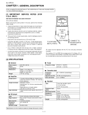
... shock hazard which must be corrected before returning the audio product to the owner.
[2] SPECIFICATIONS
I General
Power...
XL-HP515
AXSMECeLuaHrdH-vrHkiAioPcePe5tP51M1T55aEnuRal1. Inspect all exposed metal parts having a return path to the chassis (antenna, metal cabinet, screw heads, knobs and control ... in series with 1000 ohm per channel into a 120 volt AC outlet.
* Using two...
Service Manual - Page 3
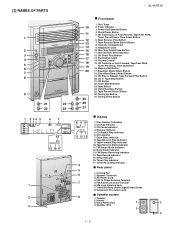
... Button 13. Memory/Set Button 17. Tape ...Control 15. Equalizer Mode Select Button 18. Extra Bass/Demo Mode Button 19. Daily Timer Indicator 13. Tape Record Indicator 15. Tuning Down Button
■ Display
8 9 10 11 12 13
4 5 6 7
1. Tape Forward Play Indicator 10. AC Power Cord 4. [3] NAMES OF PARTS
1
2 3 4 5 6 7 8
9
21
23
22
24
1 2 34 5
67
14 15 16 17
1 2 3
XL-HP515...
Service Manual - Page 4
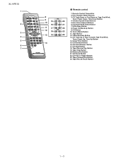
...Memory/Set Button
21. Video/Auxiliary Button
13. CD Random Button
16. Tape Stop Button
20. CD Pause Button
22. Remote Control ...Transmitter
2. Extra Bass Button
22
8. Tape Reverse Play Button
19. Tape Forward Play Button
24. Clock/Timer Button
15. Disc Number Select Buttons
3. CD Clear/Dimmer Button
17. CD Play or Repeat Button
23. XL-HP515...
Service Manual - Page 5
...compensated inside the IC.)
* Focus offset adjustment
* Tracking offset adjustment
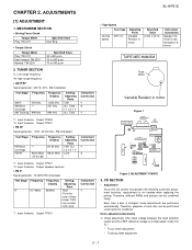
2 - 1 ADJUSTMENTS
XL-HP515
[1] ADJUSTMENT
1. Input: Antenna Output: TP302 *2.
Input: Antenna Output: TP301 *2.
Therefore, ...RF
Frequency
- 98.00 MHz (10-30 dB)
Frequency Display
87.50 kHz
98.00 MHz
Setting/ Adjusting
Point T301 (fL): 1.3 ± 0.1 V L312
Instrument Connection
*1
*2
*1. Items ...
Service Manual - Page 6

XL-HP515
2) Tracking balance adjustment 3) Gain adjustment (The gain is compensated inside the IC so that the
loop gain at... When it detect TRAY operation error during initialize process. CD ERROR CODE DESCRIPTION
Error 01
10* 11* 20*
21*
31
Explanation When Pickup set inner position, inner switch cannot detect 'ON' level for the 5th times.
2 - 2 Can't detect TRAY switch when TRAY is moving...
Service Manual - Page 7
..."
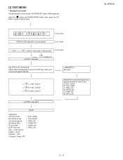
VOL - [2] TEST MODE
• Setting the test mode During stand-by mode, press ON/STAND-BY button while pressing
down the
button and X-BASS/DEMO button. OFF
To cancel : Power OFF
Adjustment result automatically will display as below for each 2 sec: a) "FOF_XXXX" b) "TOF_XXXX" c) "TBAL_XX" d) "TGAN_XX" f) "FGAN_XX" g) "RFLS_XX"
-------- XL-HP515
2 - 3 then, press the CD...
Service Manual - Page 9
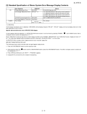
...enter stand-by pressing 'POWER', ' Computer version number will be display instead of Stereo System Error Message Display Contents
XL-HP515
CD TUNER
Error Contents
DISPLAY
Pickup Mechanism Error.
'ER-CD01'
CD Changer Mechanism ...21:TRAY SW Detection NG during version number display and then press 'POWER', 'MEMORY/SET' and 'VIDEO/AUX' button. Unplug the AC cord and the unit is condition ...
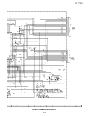
Service Manual - Page 19
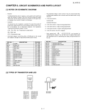
CIRCUIT SCHEMATICS AND PARTS LAYOUT
[1] NOTES ON SCHEMATIC DIAGRAM
XL-HP515
• Resistor:
To differentiate the units of the set .
In the main section, a tape is being played back.... of the capacitor without such a symbol is ohm-type resistor. In the tuner section, indicates AM indicates FM stereo
2. In the power section, a tape is the one with "
" (
) are used : this model...
Service Manual - Page 27
... MA111
D706 MA111
Q703 KRC102 S
2
3
1
C719 3.3/50
RX701 GP1UM271
REMOTE SENSOR 1 2 3
R798 100
C721 47/16
C720 0.022
R797 100K ...820
SW719 SW720
SW721
X-BASS /DEMO
EQUALIZER
MEMORY /SET
RD08
680 SW709
RD09 RD10 RD11 RD12 RD13 RD14... PRESET
DOWN
7
8
9
10
11
12
Figure 6-9 SCHEMATIC DIAGRAM (8/10) 6 - 9 XL-HP515
G6
P_IN AVREF AVDD
G6
+B
F1
F1
NP
NP
G1
G2
G3
G4
G5
09 8...
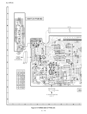
Service Manual - Page 32
...Q719
UP
B
Q714 Q712 Q713
R775
R770
C
D712
R
SW721 MEMORRY
E RD16
/SET R799 RD15
SW713 RD11 REC/PAUSE
Q702
COLOR TABLE
RD18
R566 SW717
E
C
Q715
...PWB (3/9) 6 - 14 XL-HP515
A
SW728 OPEN/ CROSE
SWITCH PWB-B2
B
RD25
SW727 DISC 5
SW726 DISC 4
RD24
RD23
SW725 DISC 3
1
FFC706
7
SW724
C
DISC 2
RD22
RD21
SW723 DISC 1
RD20
RD19
1
BI703A
RX701 REMOTE SENSOR 2
123
1 ...
Service Manual - Page 43
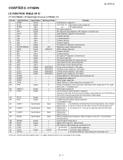
OTHERS
XL-HP515
[1] FUNCTION TABLE OF IC
IC1 VHiLC78648E-1: CD Digital Signal Processor (LC78648E) (1/2)
Pin No. ...LPF capacitor connection pin. Tracking control output pin.
nal and the internally generated Synchronization signal agree. pose I/O pin 2. Left channel L channel Power supply pin.
Thread control output pin. Analog GND pin 2.
connected to 0V, or set up as input pin ports...
Service Manual - Page 44
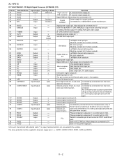
...Anti-shock
Bit clock input pin. (Must be connect to 0 V when unused.)
Left/Right channel data input pin.
(Must be connect to 0V. Bit clock output pin. Digital power supply...be either
set LOW briefly after power is (open drain output DF.
Controlled by commands from the micro-
In this unit, the terminal with asterisk mark (*) is first applied. XL-HP515
IC1 ...
Service Manual - Page 46
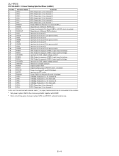
... change pin (REV). H bridge Output pin (+) for bridge. Logic input for channel 5. Input pin for channel 2. BTL Output pin (+) for BTL mute. Input pin for gain control) CH5 Output change pin (FWD). Logic input for CH5 output voltage control. Input pin for bridge. XL-HP515
IC2 VHILA6261//-1: Focus/Tracking/Spin/Sled Driver (LA6261)
Pin No. 1 2 3 4 5 6 7 8 9 10...
Service Manual - Page 55
...
MICRO COMPONENT SYSTEM
MODEL XL-HP515
XL-HP515 Micro Component System consisting of the set . The 13th character represents error.
("J" ±5%, "F" ±1%, "D" ±0.5%.)
If there are no indications for other parts, the resistors are ±5% carbon-film type. "HOW TO ORDER REPLACEMENT PARTS"
To have your nearest SHARP Parts Distributor to replace parts with " " are no indications...
Service Manual - Page 59
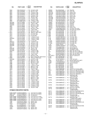
...[Main Cam] AP Motor with Gear [Sled] AM Motor,Air Cooling Fan AH Relay AH Relay AF Photo Interrupter AH Remote Sensor,GP1UM271 AD Terminal,FM Antenna AE Terminal,Speaker AZ Woofer AZ Woofer AR Tweeter AR Tweeter AD Switch,Push Type [...UP] AC Switch,Key Type
[X-BASS/DEMO] AC Switch,Key Type [EQUALISER] AC Switch,Key Type
[MEMORY/SET]
- 4 -
PART CODE
PRICE RANK
DESCRIPTION
NO. XL-HP515
NO.
Service Manual - Page 60
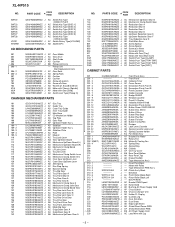
XL-HP515
NO. PART CODE
PRICE RANK
DESCRIPTION
NO. NGERR0043AFZZ J ...Up/Down Board (R) AC Mechanism Clamp Board AD L/R Joint Lever AC Tray Set Lever AC Mechanism Clamp Switch Lever AC Mechanism Clamp Switch Arm AB Inner ... AG Decoration Panel,Front B AG Panel,Cassette Cover AF Holder,Cassette AD Badge,SHARP AB Window,Cassette AD Panel,FL Display AD Indicator,Volume Knob AQ Decoration Panel...
Service Manual - Page 61
...Motor (PWB Only) AE CD Changer Motor (PWB Only)
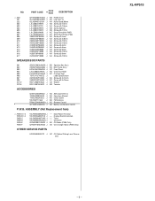
OTHER SERVICE PARTS
UDSKA0004AFZZ J AZ CD Optical Pickup Lens Cleaner Disc
XL-HP515
- 6 - PART CODE
PRICE RANK
DESCRIPTION
1 230 231 232 602 603 604 605 606 607 608 609 610 611 612...J RRMCG0408AWSA J
GFTAB1049AWSA J
AG AM Loop Antenna AE Operation Manual AD Quick Guide AD FM Antenna AS Remote Control
AE Battery Lid,Remote Control
P.W.B. NO.
Service Manual - Page 66
XL-HP515
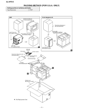
PACKING METHOD (FOR U.S.A. ONLY)
Setting position of switches and knobs
Tape Mechanism
STOP
UNIT
...Front Speaker,Top/Bottom
SPAKAA015AWZZ
Label,Pop
TLABZA024AWZZ
A
Sheet,Speaker
AM Loop
SPAKZA012AWZZ
Antenna
B
FM Antenna
Remote Control
Polyethylene Bag,Accessories 92LBAG1460C1
Operation Manual Quic Guide
Pad,Add., SPAKZA050AWZZ
B
A
Packing Case SPAKCA114AWZZ
: Not...
Service Manual - Page 68
... AV Systems Group Quality & Reliability Control Center Higashihiroshima, Hiroshima 739-0192, Japan
Printed in any form or by any means, electronic, mechanical, photocopying, recording, or otherwise, without prior written permission of the publisher. XL-HP515
COPYRIGHT © 2004 BY SHARP CORPORATION
ALL RIGHTS RESERVED.
No part of this publication may be reproduced, stored in...
Similar Questions

Replacement Of Remote Control For Sharp Cd-sw330h.
I have lost my remote control for my mini component system sharp cd-sw330h. As a result i can't chan...
I have lost my remote control for my mini component system sharp cd-sw330h. As a result i can't chan...
(Posted by tsaousi1 4 years ago)

Dial Flashing Blue Light
How do you stop the blue light on the dial from flashing constantly?
How do you stop the blue light on the dial from flashing constantly?
(Posted by b4rlpls 4 years ago)

Sharp Cd-sw200 Remote Control
I Lost My Remote Control. How Can I Buy Another?
I Lost My Remote Control. How Can I Buy Another?
(Posted by marciamoura66 10 years ago)

May I Download A Free Operating Manual For The Sharp Xp-hp515?
(Posted by jesso549 10 years ago)

Program Remote
I Forgot How To Preprogram My Remote For A Sharpxlhp515
I Forgot How To Preprogram My Remote For A Sharpxlhp515
(Posted by MO7657 11 years ago)