
Sharp XL-HP515 Support Question
Sharp XL-HP515 Support Question
Find answers below for this question about Sharp XL-HP515.Need a Sharp XL-HP515 manual? We have 1 online manual for this item!
Question posted by MO7657 on January 9th, 2013
Program Remote
I Forgot How To Preprogram My Remote For A Sharpxlhp515
Current Answers
Answer #1: Posted by Dzekii on January 9th, 2013 11:22 AM
Dzekii

Member since:
December 28th, 2012 Points: 36,010

Member since:
December 28th, 2012 Points: 36,010
-
Turn on the device that you are planning to use with the Sharp universal remote.
- 2
Point the Sharp universal remote at the device that has been turned on.
-
Press and hold down the button for that device (i.e. "TV," "VCR," etc.) and the "Channel Up" button on the Sharp universal remote for about seven seconds.
- 4
Type in the code for the device. This code can be located in the manual for that Sharp remote or on the Internet.
- 5
Press the device button you held down in step 3 to save the code.
-
Test the Sharp universal remote on the device by pressing the "Power" button. If the device does not respond to the remote, repeat the programming process starting at step 1.
- 4
Jack
Related Sharp XL-HP515 Manual Pages
Service Manual - Page 1
CIRCUIT DESCRIPTION [1] WAVEFORMS OF CD CIRCUIT 5-1 [2] VOLTAGE 5-2
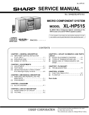
CHAPTER 6. S4422XLHP515U
MICRO COMPONENT SYSTEM
MODEL XL-HP515
XL-HP515 Micro Component System consisting of XLHP515 (main unit) and CP-HP515 (speaker system).
• In the interests of Stereo System
Error Message Display Contents 2-5
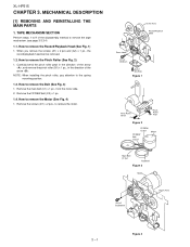
CHAPTER 3. ONLY 1-1 [2] SPECIFICATIONS 1-1 [3] NAMES OF PARTS 1-2
CHAPTER 2. ...
Service Manual - Page 2
...earth ground, such as insulating materials, cabinet, terminal board, adjustment and compartment covers or shields, mechanical insulators etc.
3.
XL-HP515
AXSMECeLuaHrdH-vrHkiAioPcePe5tP51M1T55aEnuRal1. To be corrected before returning the audio product to the owner.
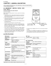
[2] SPECIFICATIONS
I General
Power source Power consumption Dimensions
Weight
I Amplifier
Output power
Output terminals
Input...
Service Manual - Page 3
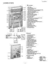
...PARTS
1
2 3 4 5 6 7 8
9
21
23
22
24
1 2 34 5
67
14 15 16 17
1 2 3
XL-HP515
10 11 12 13 14 15 16 17 18 19 20
25 26 27
I Front panel
1. FM Stereo Mode Indicator 12. Speaker Wire...Timer Recording Indicator
■ Rear panel
1. Tape Button 24. Volume Control 15. Video/Auxiliary (Audio Signal) Input Jacks 8. AM Loop Antenna Jack 7. Disc Trays 2. CD Track Down or ...
Service Manual - Page 4
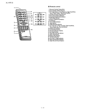
...
15. Tape Stop Button
20. CD Track Up or Fast Forward, Tape Fast Wind,
Tuner Preset Up, Time Up Button
14. XL-HP515
1
2
3 4 5 6 7
8 9 10 15
16 11 17 12 18 13 19
14
I Remote control
1. Power On/Stand-by Button
9. CD Pause Button
22. Disc Direct Search Buttons
21
6. Tape Record Pause Button...
Service Manual - Page 5
...
Frequency
450 kHz - 990 kHz
Frequency Display
1,602 kHz 531 kHz
990 kHz
Setting/ Adjusting
Parts T351 (fL): T306 1.1 ± 0.1 V (fL): T303
Instrument Connection
*1 *2
*1
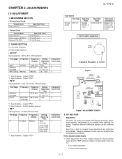
*1. ADJUSTMENTS
XL-HP515
[1] ADJUSTMENT
1. AXSMECeLuaHrdH-vrHkiAioPcePe5tP51M1T55aEnuRal2.
Service Manual - Page 6

When it detect cam operation error during initialize process. XL-HP515
2) Tracking balance adjustment 3) Gain adjustment (The gain is moving . CAM error. TRAY error. Can't detect TRAY switch when TRAY is detected, 'CHECKING' will be displayed ...
Service Manual - Page 7
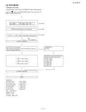
IL isn't done
A to enter the test mode. Do TOC IL. When these following key is using manual.
Last memory
P.GEQ - XL-HP515
2 - 3 then, press the CD
button to page 2-4
key input. OFF
To cancel : Power OFF
Adjustment result automatically will display as below for each 2 sec: a) "FOF_XXXX" b) "...
Service Manual - Page 8
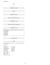
... play at that specific point. key input.
Adjustment result automatically will display as below for each 2 sec : a) "FOF_XXXX" b) "TOF_XXXX" c) "TBAL_XX" d) "TGAN_XX" f) "FGAN_XX" g) "RFLS_XX"
key input.
XL-HP515
A
key input. Tracking OFF play from that specific point. STOP
Sliding the PICKUP with>, > button must only be
2 - 4 key input.
key input.
Service Manual - Page 9
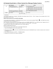
... Match/IL Time Over. Unplug the AC cord and the unit is detected, 'CHECKING' will be display instead of Stereo System Error Message Display Contents
XL-HP515
CD TUNER
Error Contents
DISPLAY
Pickup Mechanism Error.
'ER-CD01'
CD Changer Mechanism Error. 'ER-CD**' (*)
CD DSP Communication Error.
Service Manual - Page 10
... disassembly method to remove the Pinch Roller (See Fig. 2)
1. Remove the FF/REW belt (C2) x 1 pc.
1.4. How to remove the Record/Playback Head (See Fig. 1)
1. XL-HP515
AXSMECeLuaHrdH-vrHkiAioPcePe5tP51M1T55aEnuRal3. TAPE MECHANISM SECTION
Perform steps 1 to 9 of the arrow . How to remove the tape mechanism.(see page 3-3,3-4)
1.1. Remove the main belt (C1) x 1 pc...
Service Manual - Page 14
...
TAPE L 10
R 15
TUNER L 11
R 14
CD L 12
R 13
DI 1
CE 2
IC601 CLK 24
LC75341
21 R
AUDIO PROCESSOR 4 L
13
+B5
P.B 4 L PB
21 R
7 18 8 17 3 23 +B5
H/N 7 L REC 18 R
IC101 AN7345K PLAYBACK AND RECORD /PLAYBACK AMP.
XL-HP515
AXSMECeLuaHrdH-vrHkiAioPcePe5tP51M1T55aEnuRal4.
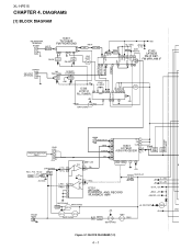
DIAGRAMS
[1] BLOCK DIAGRAM
FM ANTENNA TERMINAL
SO302
B.P.F BF301
IC301 TA7358AP FM FRONT END
1 34...
Service Manual - Page 15
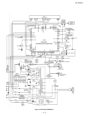
XL-HP515
SYSTEM MUTE VL+ VLñ GND
Q603 Q604
_+10V D_+8V
851
12
5 21
FL701 FL DISPLAY
28 31 32 41
+B10
44 45
... TIME LED
45 VOL_LED
AC_RLY T_SOL
T_MOTOR VDD
43 44 46
IC701
59 40 25 13 REMOCON 39 AVDD 34 33
31
VOL_JOG 30
+B3
REMOTE SENSOR
1 RX701 2
+B10
3
+B10
KEY SW701-SW705 SW709-SW728
VOLUME VR701
+B9(SW_+5V)
IXA020AW
PROTECT 29
+B_PROTECT
VDD -20dBATT T_BIAS T_REC/PLAY ...
Service Manual - Page 20
...
R
C619 1/50 10 L3
DECK
R
R614 2.2K Q602 KTC3875 GR R612 390
Q604 KTC3875 GR
C621 1/50 11 L2
TUNER
R
C
BI601
CNS2 R-CH 1
6-11 11 - XL-HP515
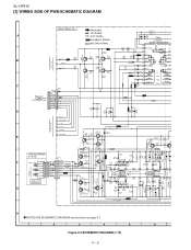
[3] WIRING SIDE OF PWB/SCHEMATIC DIAGRAM
MAIN PWB-A1(1/2)
FM SIGNAL
R601 1K
CD SIGNAL
R602 1K
C652 220P C651 220P
A
AUX SIGNAL
IC601
PLAYBACK...
Service Manual - Page 27
...L701 100µH
+B
+B
D705 MA111
D706 MA111
Q703 KRC102 S
2
3
1
C719 3.3/50
RX701 GP1UM271
REMOTE SENSOR 1 2 3
R798 100
C721 47/16
C720 0.022
R797 100K C722 150P(CH)
D707 MA111
C718... REVERSE STANDBY TIMER/ MODE PLAY PRESET
DOWN
7
8
9
10
11
12
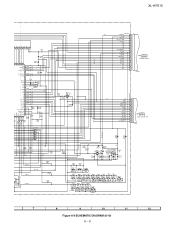
Figure 6-9 SCHEMATIC DIAGRAM (8/10) 6 - 9 XL-HP515
G6
P_IN AVREF AVDD
G6
+B
F1
F1
NP
NP
G1
G2
G3
G4
G5
09 8 7 6 5 4 3 2...
Service Manual - Page 32
XL-HP515
A
SW728 OPEN/ CROSE
SWITCH PWB-B2
B
RD25
SW727 DISC 5
SW726 DISC 4
RD24
RD23
SW725 DISC 3
1
FFC706
7
SW724
C
DISC 2
RD22
RD21
SW723 DISC 1
RD20
RD19
1
BI703A
RX701 REMOTE SENSOR 2
123
1 C722
C720
C700
BI703B
D
2 1
1 2
3
SW722
4 5
CD DIRECT
6
CNP704
PLAY
7 8
CNP5
6-17 9 - C
H
1
2
3
4
5
6
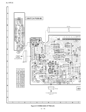
Figure 6-14 WIRING SIDE OF PWB (3/9) 6 - 14 G TO CD ...
Service Manual - Page 48
XL-HP515
IC601 VHiLC75341/-1: Audio Processor (LC75341)
Pin No. 1 2
3 4
5 6 7 8 9-12
Terminal Name DI CE
VSS LOUT
LBASS LTRE LIN LSEL0 L4-1
...capacitor and resistor connection pin. Data written into an internal latch in a timing of several 10µF to "L". IC601 VHiLC75341/-1: Audio Processor (LC75341)
Pin No. 13-16 17 18 19 20 21
22
23 24
Terminal Name R1-4 RSEL0 RIN RTRE RBASS ROUT...
Service Manual - Page 55
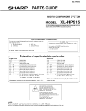
... • • CY Square type (without lead wire) VR • • CZ Square type (without lead wire) VC J ..
PART NO.
4.
No. PARTS GUIDE
XL-HP515
MICRO COMPONENT SYSTEM
MODEL XL-HP515
XL-HP515 Micro Component System consisting of capacitors/resistors parts codes
Capacitors
VCC Ceramic type VCK Ceramic type VCT Semiconductor type VC • • MF Cylindrical type...
Service Manual - Page 59
XL-HP515
NO. PART CODE
PRICE RANK
DESCRIPTION
NO.
PARTS CODE
PRICE RANK
DESCRIPTION
R843 R844 R853 R854 R857 R858 R859 R863 R864...Motor with Gear [Main Cam] AP Motor with Gear [Sled] AM Motor,Air Cooling Fan AH Relay AH Relay AF Photo Interrupter AH Remote Sensor,GP1UM271 AD Terminal,FM Antenna AE Terminal,Speaker AZ Woofer AZ Woofer AR Tweeter AR Tweeter AD Switch,Push Type [CLAMP] AD ...
Service Manual - Page 61
...CD Motor (PWB Only) AE CD Changer Motor (PWB Only)
OTHER SERVICE PARTS
UDSKA0004AFZZ J AZ CD Optical Pickup Lens Cleaner Disc
XL-HP515
- 6 - ASSEMBLY (Not Replacement Item)
1 PWB-A1~3 PWB-B1~4 PWB-C PWB-D PWB-E PWB-F
92LPWB5609MANS J 92LPWB5609DPLS ... Manual AD Quick Guide AD FM Antenna AS Remote Control
AE Battery Lid,Remote Control
P.W.B. Tuner -- Display/Switch/Led/Jack --
Service Manual - Page 66
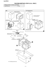
XL-HP515
PACKING METHOD (FOR U.S.A. ONLY)
Setting position of switches and knobs
Tape Mechanism
...Packing,Add., Front Speaker,Top/Bottom
SPAKAA015AWZZ
Label,Pop
TLABZA024AWZZ
A
Sheet,Speaker
AM Loop
SPAKZA012AWZZ
Antenna
B
FM Antenna
Remote Control
Polyethylene Bag,Accessories 92LBAG1460C1
Operation Manual Quic Guide
Pad,Add., SPAKZA050AWZZ
B
A
Packing Case SPAKCA114AWZZ
: Not ...
Similar Questions

Dial Flashing Blue Light
How do you stop the blue light on the dial from flashing constantly?
How do you stop the blue light on the dial from flashing constantly?
(Posted by b4rlpls 4 years ago)

Where Can I Get A Remote For My Xl-uh242
I need a replacement remote control for my XL-UH242 unit
I need a replacement remote control for my XL-UH242 unit
(Posted by Mamaliza 10 years ago)

May I Download A Free Operating Manual For The Sharp Xp-hp515?
(Posted by jesso549 10 years ago)

Setting Sharp Stereo Shelf System Xl Hp515 Remote Control
Please help me set my remote control channels for my Hl hp515
Please help me set my remote control channels for my Hl hp515
(Posted by Cigarman8 10 years ago)