Service Manual
Page 1
... nm Laser Pulse Times : (13.95 ± 3 µs)/7mm Laser Output Power : 0.4 mW ± 0.05mW Parts marked with the connector connected when removing and installing the optical system. 4) The cover of the CDRH or IEC60825-1 standard. The use of controls, adjustments or performance of procedures other items into the laser beam exposure slit of the laser optical unit with " " is important for after removing the toner/developer unit and drum cartridge. 3) Do...
... nm Laser Pulse Times : (13.95 ± 3 µs)/7mm Laser Output Power : 0.4 mW ± 0.05mW Parts marked with the connector connected when removing and installing the optical system. 4) The cover of the CDRH or IEC60825-1 standard. The use of controls, adjustments or performance of procedures other items into the laser beam exposure slit of the laser optical unit with " " is important for after removing the toner/developer unit and drum cartridge. 3) Do...

Service Manual
Page 2
... of power supply PWB 5-23 [5] Circuit description of CIS UNIT 5-24 CHAPTER 6. GENERAL DESCRIPTION [1] Specifications 1-1 [2] Operation panel 1-2 [3] Transmittable documents 1-3 [4] Installation 1-4 [5] Maintenance 1-11 [6] Troubleshooting 1-12 [7] Quick reference guide 1-14 CHAPTER 2. ADJUSTMENTS [1] Adjustments 2-1 [2] Diagnostics and service soft switches 2-4 [3] Troubleshooting 2-26 [4] Error code table 2-27 CHAPTER 3. CIRCUIT SCHEMATICS AND PARTS LAYOUT [1] Control PWB circuit 6-1 [2] TEL/LIU and Hook SW PWB circuit 6-12 [3] Printer PWB circuit 6-14 [4] Power supply PWB...
... of power supply PWB 5-23 [5] Circuit description of CIS UNIT 5-24 CHAPTER 6. GENERAL DESCRIPTION [1] Specifications 1-1 [2] Operation panel 1-2 [3] Transmittable documents 1-3 [4] Installation 1-4 [5] Maintenance 1-11 [6] Troubleshooting 1-12 [7] Quick reference guide 1-14 CHAPTER 2. ADJUSTMENTS [1] Adjustments 2-1 [2] Diagnostics and service soft switches 2-4 [3] Troubleshooting 2-26 [4] Error code table 2-27 CHAPTER 3. CIRCUIT SCHEMATICS AND PARTS LAYOUT [1] Control PWB circuit 6-1 [2] TEL/LIU and Hook SW PWB circuit 6-12 [3] Printer PWB circuit 6-14 [4] Power supply PWB...

Service Manual
Page 3
...: 196 lines/inch (7.7 lines/mm) Super fine: 391 lines/inch (15.4 lines/mm) PC: Enhanced 600 dpi Automatic document feeder 20 pages max. (20-lb. Effective Printing width 8.0" (210 mm) max. Transmission time* Approx. 6 seconds Toner cartridge yield (4% page coverage, letter paper) Initial starter cartridge (included with fax machine): Approx. 1,875 pages Replacement cartridge (UX-400ND): Approx. 3,750 pages Drum cartridge yield Initial starter cartridge (included with supplies, please don't use new supplies, when supply changes are required...
...: 196 lines/inch (7.7 lines/mm) Super fine: 391 lines/inch (15.4 lines/mm) PC: Enhanced 600 dpi Automatic document feeder 20 pages max. (20-lb. Effective Printing width 8.0" (210 mm) max. Transmission time* Approx. 6 seconds Toner cartridge yield (4% page coverage, letter paper) Initial starter cartridge (included with fax machine): Approx. 1,875 pages Replacement cartridge (UX-400ND): Approx. 3,750 pages Drum cartridge yield Initial starter cartridge (included with supplies, please don't use new supplies, when supply changes are required...

Service Manual
Page 4
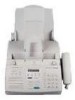
... telephone line. 9 RECEPTION MODE key Press this key to the fax machine. 8 LINE IN USE light This lights when the fax machine is using Speed Dialing, Direct Keypad Dialing, or Normal Dialing. 19 COPY/HELP key When a document is in the display will open , or a paper size error has occurred. 4 TONER EMPTY indicator This blinks when the toner cartridge nears empty and lights steadily when the toner cartridge needs replacement. 5 Display This displays messages...
... telephone line. 9 RECEPTION MODE key Press this key to the fax machine. 8 LINE IN USE light This lights when the fax machine is using Speed Dialing, Direct Keypad Dialing, or Normal Dialing. 19 COPY/HELP key When a document is in the display will open , or a paper size error has occurred. 4 TONER EMPTY indicator This blinks when the toner cartridge nears empty and lights steadily when the toner cartridge needs replacement. 5 Display This displays messages...

Service Manual
Page 6
...... light, and dust. • Provide easy access to remove the black sheet of protective paper from a cold to open the cover. • Caution! UX-4000MU FO-2950MU/C [4] Installation 1. Caution! • Connection to a power source other than that the reading glass may result in your fax can print approximately 1,875 letter-size pages st 4% page coverage When replacing the toner cartridge, use a Sharp UX-400DR drum cartridge. The fusing unit inside of the compartment or the paper guide on...
...... light, and dust. • Provide easy access to remove the black sheet of protective paper from a cold to open the cover. • Caution! UX-4000MU FO-2950MU/C [4] Installation 1. Caution! • Connection to a power source other than that the reading glass may result in your fax can print approximately 1,875 letter-size pages st 4% page coverage When replacing the toner cartridge, use a Sharp UX-400DR drum cartridge. The fusing unit inside of the compartment or the paper guide on...

Service Manual
Page 9
... a standard (RJ11C) single-line wall telephone jack. 4 Attaching the paper tray and document supports. 1) Attach the paper tray. 2) Attach the received document tray. Insert the other kind of the support faces you (the support should curve slightly toward you must set for tone dialing. Be sure to the date and time display. Press the keys on the fax. 1) Remove the seal covering the TEL. SET jack...
... a standard (RJ11C) single-line wall telephone jack. 4 Attaching the paper tray and document supports. 1) Attach the paper tray. 2) Attach the received document tray. Insert the other kind of the support faces you (the support should curve slightly toward you must set for tone dialing. Be sure to the date and time display. Press the keys on the fax. 1) Remove the seal covering the TEL. SET jack...

Service Manual
Page 10
...; Note: If the paper does not feed correctly, remove the entire stack from the tray and repeat the loading procedure from the beginning. 3 Pull the paper release lever toward you. 1 - 8 manuals4you.com Caution! Do not use the blank side of the paper. UX-4000MU FO-2950MU/C 2) Connect the extension phone line to load the paper so that printing takes place on the print side of paper that the stack...
...; Note: If the paper does not feed correctly, remove the entire stack from the tray and repeat the loading procedure from the beginning. 3 Pull the paper release lever toward you. 1 - 8 manuals4you.com Caution! Do not use the blank side of the paper. UX-4000MU FO-2950MU/C 2) Connect the extension phone line to load the paper so that printing takes place on the print side of paper that the stack...

Service Manual
Page 11
... inside the print compartment becomes very hot during transmission or copying, or DOCUMENT JAMMED appears in the display, first try to scale the size of the compartment. 1 - 9 If you have loaded legal paper, you are unable to clear the jam in the paper tray, and push down the paper release lever. • If you must change the paper size setting to open the operation panel and remove it clicks...
... inside the print compartment becomes very hot during transmission or copying, or DOCUMENT JAMMED appears in the display, first try to scale the size of the compartment. 1 - 9 If you have loaded legal paper, you are unable to clear the jam in the paper tray, and push down the paper release lever. • If you must change the paper size setting to open the operation panel and remove it clicks...

Service Manual
Page 15
... reception if too much data is jammed. LINE IS IN USE MEMORY IS FULL An extention phone connected to memory because printing is completed. The toner cartridge must be printed out. Intermittent tone 5 seconds Indacates incomplete (3 beeps) (1 seconds on , set is jammed. This message will indicate the problem), resolve the problem so that indicates the problem. The printing paper is received before the pages can continue. Change the paper size setting. HOLD The HOLD...
... reception if too much data is jammed. LINE IS IN USE MEMORY IS FULL An extention phone connected to memory because printing is completed. The toner cartridge must be printed out. Intermittent tone 5 seconds Indacates incomplete (3 beeps) (1 seconds on , set is jammed. This message will indicate the problem), resolve the problem so that indicates the problem. The printing paper is received before the pages can continue. Change the paper size setting. HOLD The HOLD...

Service Manual
Page 19
... 4 DISPLAY: OPTION SETTING PRESS or # (step 2) Select "DIAL MODE". DISPLAY: DIAL MODE 1= TONE, 2= PULSE (step 3) Select, using the "STOP" key. SW2 DATA No. 1) Use this to set the fax machine to the type of telephone line you are on. • The factory setting is open, replace it with a new one. 4. IC protectors replacement ICPs (IC Protectors) are shown below: (1) F100 (ICPS10) is indicated because the number of ICPs are installed to...
... 4 DISPLAY: OPTION SETTING PRESS or # (step 2) Select "DIAL MODE". DISPLAY: DIAL MODE 1= TONE, 2= PULSE (step 3) Select, using the "STOP" key. SW2 DATA No. 1) Use this to set the fax machine to the type of telephone line you are on. • The factory setting is open, replace it with a new one. 4. IC protectors replacement ICPs (IC Protectors) are shown below: (1) F100 (ICPS10) is indicated because the number of ICPs are installed to...

Service Manual
Page 20
... • specifications) FUNC 9 8 6 PRINT DIAG MODE START 01 START AREA PRINT MODE 02 START CHECK PATTERN 1 03 START CHECK PATTERN 2 04 START CHECK PATTERN 3 05 START PAPER FEED AGING 06 START LIFE SET MODE 07 START LIFE ALL CLEAR 08 START LIFE ENTRY MODE 09 START TOP ADJUST MODE 10 START LIFE CLEAR MODE 11 START MAIN CHARGER ADJUST Memory clear when power is used for production and service support. UX-4000MU FO-2950MU/C [2] Diagnostics and service soft switches 1. Enter the mode with...
... • specifications) FUNC 9 8 6 PRINT DIAG MODE START 01 START AREA PRINT MODE 02 START CHECK PATTERN 1 03 START CHECK PATTERN 2 04 START CHECK PATTERN 3 05 START PAPER FEED AGING 06 START LIFE SET MODE 07 START LIFE ALL CLEAR 08 START LIFE ENTRY MODE 09 START TOP ADJUST MODE 10 START LIFE CLEAR MODE 11 START MAIN CHARGER ADJUST Memory clear when power is used for production and service support. UX-4000MU FO-2950MU/C [2] Diagnostics and service soft switches 1. Enter the mode with...

Service Manual
Page 22
... 2 line are .) Rapid key RXX XX : Rapid number SPEED key SXX XX : Speed key number (12th and subsequential letters of FAX/TEL No. UX-4000MU FO-2950MU/C 8) Memory clear mode This mode is activated, the document size A4(A4 ) and sensor information A4(A4 ORG) are registered in the group number 04. When the START key is printed on multiple pages. Rapid key 04: Check pattern...
... 2 line are .) Rapid key RXX XX : Rapid number SPEED key SXX XX : Speed key number (12th and subsequential letters of FAX/TEL No. UX-4000MU FO-2950MU/C 8) Memory clear mode This mode is activated, the document size A4(A4 ) and sensor information A4(A4 ORG) are registered in the group number 04. When the START key is printed on multiple pages. Rapid key 04: Check pattern...

Service Manual
Page 23
... counters are described as numbers of printed pages from the beginning of use ? If the life of a consumable part (developer, imprinter, etc) is set value. You can be moved closer to another counter with the follow- 1ing procedure. Rapid key 05: Paper feed aging The mode is used to clear the life counter of the printer of the counter of the auto feeder. Here, the operation in the whole black (whole black) printing...
... counters are described as numbers of printed pages from the beginning of use ? If the life of a consumable part (developer, imprinter, etc) is set value. You can be moved closer to another counter with the follow- 1ing procedure. Rapid key 05: Paper feed aging The mode is used to clear the life counter of the printer of the counter of the auto feeder. Here, the operation in the whole black (whole black) printing...

Service Manual
Page 36
... cover sheet When "0" (=YES) is selected, the cover sheet is used as to how many recall times should be made. If it was above 9 by stops. 0: Yes 1: No SW2 No. 5 Polling security This switch is displayed in auto dial Delay time between the line connection and dial data output under the auto dial mode. If it was set to 1, a direct connection is set to 9. When set to 0 accidentally, 1 will be set . UX-4000MU...
... cover sheet When "0" (=YES) is selected, the cover sheet is used as to how many recall times should be made. If it was above 9 by stops. 0: Yes 1: No SW2 No. 5 Polling security This switch is displayed in auto dial Delay time between the line connection and dial data output under the auto dial mode. If it was set to 1, a direct connection is set to 9. When set to 0 accidentally, 1 will be set . UX-4000MU...

Service Manual
Page 85
... is set by the laser beam sensor to turn on the LEND_ signal before starting the LEND process. Stop Start Clock of resolution The CPU control 600dpi/400dpi when starting printing. Fig. 10 4) LEND process operation The LEND process operation means outputting the HSYNC (HSYNC_) signal for scanner motor speed control. It repeated ON and OFF for controlling the print left margin control. UX...
... is set by the laser beam sensor to turn on the LEND_ signal before starting the LEND process. Stop Start Clock of resolution The CPU control 600dpi/400dpi when starting printing. Fig. 10 4) LEND process operation The LEND process operation means outputting the HSYNC (HSYNC_) signal for scanner motor speed control. It repeated ON and OFF for controlling the print left margin control. UX...

Service Manual
Page 94
... H L L High - Fixed - H: The handset or external telephone is inputted from output port] Signal Name Description CML Line connecting relay and DP generating relay H: Line make L: Line break SP MUTE Speaker tone mute control signal H: Muting (Power down mode) L: Muting cancel (Normal operation) TEL MUTE Handset reception mute control signal H: Muting L: Muting cancel RCVOL Handset receiver volume control signal Volume High Middle Low (The circuit is located in...
... H L L High - Fixed - H: The handset or external telephone is inputted from output port] Signal Name Description CML Line connecting relay and DP generating relay H: Line make L: Line break SP MUTE Speaker tone mute control signal H: Muting (Power down mode) L: Muting cancel (Normal operation) TEL MUTE Handset reception mute control signal H: Muting L: Muting cancel RCVOL Handset receiver volume control signal Volume High Middle Low (The circuit is located in...

Service Manual
Page 143
... use any of the commands described below, go to the View menu and select the desired command. • Toolbar Select Toolbar to hide and display the Toolbar. • Status Bar Select Status Bar to hide and display the Status Bar. • Image Toolbox While in Page View mode, select Image Toolbox to hide and display the Image Toolbox. • Sort The Sort command enables...
... use any of the commands described below, go to the View menu and select the desired command. • Toolbar Select Toolbar to hide and display the Toolbar. • Status Bar Select Status Bar to hide and display the Status Bar. • Image Toolbox While in Page View mode, select Image Toolbox to hide and display the Image Toolbox. • Sort The Sort command enables...

Service Manual
Page 153
...; Add... EDITING AND HANDLING OF IMAGE FILES 3-15 Select messages by clicking on them once. • Font... Click this button to open the Rubber Stamp Font dialog box. (See "Rubber Stamp Font Dialog Box" in the area to use as a stamp on your changes without making any changes. • Apply Click on Apply to save your changes and exit the dialog box. • Cancel Click...
...; Add... EDITING AND HANDLING OF IMAGE FILES 3-15 Select messages by clicking on them once. • Font... Click this button to open the Rubber Stamp Font dialog box. (See "Rubber Stamp Font Dialog Box" in the area to use as a stamp on your changes without making any changes. • Apply Click on Apply to save your changes and exit the dialog box. • Cancel Click...

Service Manual
Page 166
... Bin. 3-28 EDITING AND HANDLING OF IMAGE FILES manuals4you.com All applications with the application pre-selected. To avoid wasting hard disk space, you should throw away the temporary file every time you send a document to a linked application. This name will be assigned a randomly generated 8-character name. To disable the link, click the Disable button. With the exception of the document window...
... Bin. 3-28 EDITING AND HANDLING OF IMAGE FILES manuals4you.com All applications with the application pre-selected. To avoid wasting hard disk space, you should throw away the temporary file every time you send a document to a linked application. This name will be assigned a randomly generated 8-character name. To disable the link, click the Disable button. With the exception of the document window...

Service Manual
Page 170
... Help file for the Printer Driver. About the Printer Driver The printer driver is printed. You can be found in the Driver Setup tab of the Help file, select the Help tab and then click on the Properties button in the file you want to know more about. To open the table of contents of the Sharp Laser Multifunction Properties window. Printing can also access the Printer Driver settings from a professional-grade laser printer.
... Help file for the Printer Driver. About the Printer Driver The printer driver is printed. You can be found in the Driver Setup tab of the Help file, select the Help tab and then click on the Properties button in the file you want to know more about. To open the table of contents of the Sharp Laser Multifunction Properties window. Printing can also access the Printer Driver settings from a professional-grade laser printer.


