
Operation Manual
Page 1
OPERATION MANUAL MODEL PG-M20S DIGITAL MULTIMEDIA PROJECTOR Introduction Setup and Connections Basic Operation Easy to Use Functions Appendix
OPERATION MANUAL MODEL PG-M20S DIGITAL MULTIMEDIA PROJECTOR Introduction Setup and Connections Basic Operation Easy to Use Functions Appendix
Operation Manual
Page 2
..., joita on the bottom of the projector and retain this information. Este equipamento obedece às exigências das directivas 89/336/CEE e 73/23/CEE, na sua versão corrigida pela directiva 93/68/CEE. Model No.: PG-M20S Serial No.: This equipment complies with ...the requirements of "Supplied accessories" on page 14. IMPORTANT For your assistance in reporting the loss or theft of your Projector, please record the Serial Number located on muutettu direktiivillä...
..., joita on the bottom of the projector and retain this information. Este equipamento obedece às exigências das directivas 89/336/CEE e 73/23/CEE, na sua versão corrigida pela directiva 93/68/CEE. Model No.: PG-M20S Serial No.: This equipment complies with ...the requirements of "Supplied accessories" on page 14. IMPORTANT For your assistance in reporting the loss or theft of your Projector, please record the Serial Number located on muutettu direktiivillä...
Operation Manual
Page 5
... to the presence of uninsulated "dangerous voltage" within a triangle is operated in accordance with the operation manual, may cause harmful interference to your new SHARP Projector, using the projector, please read this equip- CAUTION RISK OF ELECTRIC SHOCK. DO NOT REMOVE SCREWS EXCEPT SPECIFIED USER SERVICE SCREWS. REFER SERVICING TO QUALIFIED SERVICE PERSONNEL...
... to the presence of uninsulated "dangerous voltage" within a triangle is operated in accordance with the operation manual, may cause harmful interference to your new SHARP Projector, using the projector, please read this equip- CAUTION RISK OF ELECTRIC SHOCK. DO NOT REMOVE SCREWS EXCEPT SPECIFIED USER SERVICE SCREWS. REFER SERVICING TO QUALIFIED SERVICE PERSONNEL...
Operation Manual
Page 6
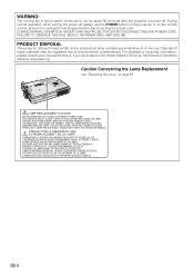
...turned off always use the POWER button on the projector or on page 71. LAMP REPLACEMENT CAUTION BEFORE REMOVING THE SCREW, DISCONNECT POWER CORD. HANDLE WITH CARE. NE REMPLACER QUE PAR UNE LAMPE SHARP DE TYPE BQC-PGM20X//1. Caution Concerning the Lamp ...A MANIPULER AVEC PRECAUTION, SE REPORTER AU MODE D'EMPLOI. -2 RAYONS ULTRAVIOLETS : PEUVENT ENDOMMAGER LES YEUX. DURING NORMAL OPERATION, NEVER TURN THE PROJECTOR OFF BY DISCONNECTING THE POWER CORD. HOT SURFACE INSIDE. LAMPE A MOYENNE PRESSION : RISQUE D'EXPLOSION. L'INTERIEUR DU BOITIER ETANT EXTREMEMENT CHAUD, ...
...turned off always use the POWER button on the projector or on page 71. LAMP REPLACEMENT CAUTION BEFORE REMOVING THE SCREW, DISCONNECT POWER CORD. HANDLE WITH CARE. NE REMPLACER QUE PAR UNE LAMPE SHARP DE TYPE BQC-PGM20X//1. Caution Concerning the Lamp ...A MANIPULER AVEC PRECAUTION, SE REPORTER AU MODE D'EMPLOI. -2 RAYONS ULTRAVIOLETS : PEUVENT ENDOMMAGER LES YEUX. DURING NORMAL OPERATION, NEVER TURN THE PROJECTOR OFF BY DISCONNECTING THE POWER CORD. HOT SURFACE INSIDE. LAMPE A MOYENNE PRESSION : RISQUE D'EXPLOSION. L'INTERIEUR DU BOITIER ETANT EXTREMEMENT CHAUD, ...

Operation Manual
Page 7
... Function Supports sRGB (color management). • Noise Reduction Allows for a clear image even with minimal distortion. 4. Image Quality • Superior image quality with previous generation DLP™ projectors. • Newly developed 12° DMD™ chip provides significantly improved opti- cal efficiency and excellent contrast ratio. 2. Light, Compact, and Unique Slim Design...
... Function Supports sRGB (color management). • Noise Reduction Allows for a clear image even with minimal distortion. 4. Image Quality • Superior image quality with previous generation DLP™ projectors. • Newly developed 12° DMD™ chip provides significantly improved opti- cal efficiency and excellent contrast ratio. 2. Light, Compact, and Unique Slim Design...

Operation Manual
Page 8
...Size and Projection Distance 18 Projecting a Reversed/Inverted Image 19 Connecting the Projector to Other Devices .... 20 Before Connecting 20 This projector can be connected to 20 Connecting the Power Cord 20 Connecting the Projector to a Computer .......... 21 Connecting to Video Equipment 23 Connecting to a...Displaying the Lamp Usage Time 58 Displaying the Break Timer 59 Reversing/Inverting Projected Images 60 Locking the Operation Buttons on the Projector 60 Setting up the Keylock 60 Canceling the Keylock Setting 61 Setting up a Password 61 Entering the Password 61 Changing the...
...Size and Projection Distance 18 Projecting a Reversed/Inverted Image 19 Connecting the Projector to Other Devices .... 20 Before Connecting 20 This projector can be connected to 20 Connecting the Power Cord 20 Connecting the Projector to a Computer .......... 21 Connecting to Video Equipment 23 Connecting to a...Displaying the Lamp Usage Time 58 Displaying the Break Timer 59 Reversing/Inverting Projected Images 60 Locking the Operation Buttons on the Projector 60 Setting up the Keylock 60 Canceling the Keylock Setting 61 Setting up a Password 61 Entering the Password 61 Changing the...

Operation Manual
Page 9
Introduction Setting the Anti-Theft 63 Entering the Keycode 63 Changing the Keycode 64 Initializing the Settings 65 Displaying the Adjustment Settings 66 Appendix Carrying the Projector 68 Maintenance 69 Maintenance Indicators 70 Regarding the Lamp 71 Lamp 71 Caution Concerning the Lamp 71 Replacing the Lamp 71 Removing and Installing the Lamp Unit 72 Resetting the Lamp Timer 73 Connecting Pin Assignments 74 Computer Compatibility Chart 75 Troubleshooting 76 For SHARP Assistance 78 Specifications 79 Dimensions 80 Glossary 81 Index 82 -5
Introduction Setting the Anti-Theft 63 Entering the Keycode 63 Changing the Keycode 64 Initializing the Settings 65 Displaying the Adjustment Settings 66 Appendix Carrying the Projector 68 Maintenance 69 Maintenance Indicators 70 Regarding the Lamp 71 Lamp 71 Caution Concerning the Lamp 71 Replacing the Lamp 71 Removing and Installing the Lamp Unit 72 Resetting the Lamp Timer 73 Connecting Pin Assignments 74 Computer Compatibility Chart 75 Troubleshooting 76 For SHARP Assistance 78 Specifications 79 Dimensions 80 Glossary 81 Index 82 -5

Operation Manual
Page 12
...the unit. Internal cleaning should be performed by a Sharp Authorized Projector Dealer or Service Center. I The placement range (the horizontal angle) should only be within ±10 degrees. This does not indicate a malfunction. Remove the projector power cord from the wall outlet and wait at ... are not obstructed. Caution concerning the lamp unit I If the projector starts to overheat due to maintain high image qual- ity, SHARP recommends that the intake vent and the exhaust vent are using the projector overseas, be connected. Do not set up your eyes tired. ...
...the unit. Internal cleaning should be performed by a Sharp Authorized Projector Dealer or Service Center. I The placement range (the horizontal angle) should only be within ±10 degrees. This does not indicate a malfunction. Remove the projector power cord from the wall outlet and wait at ... are not obstructed. Caution concerning the lamp unit I If the projector starts to overheat due to maintain high image qual- ity, SHARP recommends that the intake vent and the exhaust vent are using the projector overseas, be connected. Do not set up your eyes tired. ...
Operation Manual
Page 14
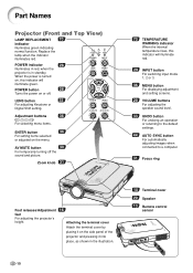
...adjusting Keystone or Digital Shift setting. AV MUTE button 30 For temporarily turning off . POWER indicator 28 Illuminates in red, when the projector is turned on, this indicator will illuminate green. When the power is in the illustration. 10 Terminal cover 29 Speaker 13 Remote control...16 Attaching the terminal cover Attach the terminal cover by placing it on the side panel of the projector and pressing it into place, as shown in standby. Part Names Projector (Front and Top View) LAMP REPLACEMENT 70 indicator Illuminates green indicating normal function. Replace the lamp...
...adjusting Keystone or Digital Shift setting. AV MUTE button 30 For temporarily turning off . POWER indicator 28 Illuminates in red, when the projector is turned on, this indicator will illuminate green. When the power is in the illustration. 10 Terminal cover 29 Speaker 13 Remote control...16 Attaching the terminal cover Attach the terminal cover by placing it on the side panel of the projector and pressing it into place, as shown in standby. Part Names Projector (Front and Top View) LAMP REPLACEMENT 70 indicator Illuminates green indicating normal function. Replace the lamp...

Operation Manual
Page 15
... USB cable. 21 INPUT AUDIO terminal Shared audio terminal for DVI digital, computer RGB, and COMPONENT signals. Using the Kensington Lock • This projector has a Kensington Security Standard connector for use it to the lens, as shown in the illustration. INPUT 2 terminal 24 Terminal for instructions on ...the lens cap, pass the other end of the strap through the hole under the projector, next to secure the projector. Attaching the lens cap After putting the lens cap strap on how to use with the system for connecting video equipment ...
... USB cable. 21 INPUT AUDIO terminal Shared audio terminal for DVI digital, computer RGB, and COMPONENT signals. Using the Kensington Lock • This projector has a Kensington Security Standard connector for use it to the lens, as shown in the illustration. INPUT 2 terminal 24 Terminal for instructions on ...the lens cap, pass the other end of the strap through the hole under the projector, next to secure the projector. Attaching the lens cap After putting the lens cap strap on how to use with the system for connecting video equipment ...

Operation Manual
Page 17
..." size, UM/SUM-4, HP-16 or similar)) are kept. Please follow the precautions below. Be sure to replace them as soon as possible with this projector may cause them using a cloth. • The batteries included with new batteries. • Remove the batteries from the remote control can be using the... to the screen material. Using the Remote Control Introduction Available Range of the Remote Control I The remote control can be used to control the projector within the ranges shown in the direction of the arrow to close it. Note • The signal from the remote control if you will not...
..." size, UM/SUM-4, HP-16 or similar)) are kept. Please follow the precautions below. Be sure to replace them as soon as possible with this projector may cause them using a cloth. • The batteries included with new batteries. • Remove the batteries from the remote control can be using the... to the screen material. Using the Remote Control Introduction Available Range of the Remote Control I The remote control can be used to control the projector within the ranges shown in the direction of the arrow to close it. Note • The signal from the remote control if you will not...

Operation Manual
Page 18
...conversion connector (commercially available) may not be necessary. Note • All cables may be available in your nearest Sharp Authorized Projector Dealer or Service Center. -14 For Europe, except U.K. For U.K., Hong Kong For Australia, New QACCDA007WJPZ QACCV4002CEZZ ...and Singapore Zealand and Oceania Note QACCBA012WJPZ QACCL3022CEZZ • Depending on the region, projectors only ship with your country. Accessories Supplied accessories Remote control RRMCGA013WJSA Two R-03 batteries ("AAA" size, UM/SUM-4, HP...
...conversion connector (commercially available) may not be necessary. Note • All cables may be available in your nearest Sharp Authorized Projector Dealer or Service Center. -14 For Europe, except U.K. For U.K., Hong Kong For Australia, New QACCDA007WJPZ QACCV4002CEZZ ...and Singapore Zealand and Oceania Note QACCBA012WJPZ QACCL3022CEZZ • Depending on the region, projectors only ship with your country. Accessories Supplied accessories Remote control RRMCGA013WJSA Two R-03 batteries ("AAA" size, UM/SUM-4, HP...

Operation Manual
Page 20
... its height and remove your fingers caught in the area between the adjustment feet and the projector. -16 Foot releases Adjustment feet Up Down Setup Using the Adjustment Feet The height of the projector is placed on is uneven or when the screen is in a location lower than the screen... press the foot releases when the feet are extended without firmly holding the projector. • Do not hold the projector firmly, press the foot releases and then lower it is slanted. Note • When returning the projector to make minor changes. The projection of the image can be adjusted using...
... its height and remove your fingers caught in the area between the adjustment feet and the projector. -16 Foot releases Adjustment feet Up Down Setup Using the Adjustment Feet The height of the projector is placed on is uneven or when the screen is in a location lower than the screen... press the foot releases when the feet are extended without firmly holding the projector. • Do not hold the projector firmly, press the foot releases and then lower it is slanted. Note • When returning the projector to make minor changes. The projection of the image can be adjusted using...

Operation Manual
Page 21
... feet flat and level to achieve an optimal image. Close the curtains and dim the lights when setting up the Screen Position the projector perpendicular to the screen with this projector. If the Audience projected image is not perpendicular to the screen. -17 ing the...projec- Setup and Connections Setting up the screen in a sunny or bright room. • A polarizing screen cannot be used , when plac- Note • The projector lens should be centered in the middle of Standard Setup • The distance from the screen according to the desired picture size. (See page 18...
... feet flat and level to achieve an optimal image. Close the curtains and dim the lights when setting up the Screen Position the projector perpendicular to the screen with this projector. If the Audience projected image is not perpendicular to the screen. -17 ing the...projec- Setup and Connections Setting up the screen in a sunny or bright room. • A polarizing screen cannot be used , when plac- Note • The projector lens should be centered in the middle of Standard Setup • The distance from the screen according to the desired picture size. (See page 18...
Operation Manual
Page 23
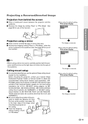
... the lens. I Place a mirror (normal flat type) in "PRJ Mode". The image is reversed. Before mounting the projector, contact your nearest Sharp Authorized Projector Dealer or Service Center to obtain the recommended ceiling-mount bracket (sold separately.) (ANPGCM90 ceiling-mount bracket, its AN-EP101B ... Reversed/Inverted Image Projection from the lens center position (see page 18) to the lower edge of the image, when mounting the projector on the audience side. When using the default setting. When using the default setting. I Reverse the image by setting "Rear" ...
... the lens. I Place a mirror (normal flat type) in "PRJ Mode". The image is reversed. Before mounting the projector, contact your nearest Sharp Authorized Projector Dealer or Service Center to obtain the recommended ceiling-mount bracket (sold separately.) (ANPGCM90 ceiling-mount bracket, its AN-EP101B ... Reversed/Inverted Image Projection from the lens center position (see page 18) to the lower edge of the image, when mounting the projector on the audience side. When using the default setting. When using the default setting. I Reverse the image by setting "Rear" ...

Operation Manual
Page 24
... used to describe the new digital television system in the supplied power cord into the AC socket on after all connections, turn off both the projector and the devices to be connected before making all the connections are made. • Be sure to 15-pin D-sub cable (See page 21.) I A DVI... equipment (See page 24.) *DTV is the last device to be turned on the rear of the devices to be connected. After making connections. This projector can be connected to: A computer using : I A VCR, Laser disc player or other devices. A monitor using : I A DVI to read the operation manuals of ...
... used to describe the new digital television system in the supplied power cord into the AC socket on after all connections, turn off both the projector and the devices to be connected before making all the connections are made. • Be sure to 15-pin D-sub cable (See page 21.) I A DVI... equipment (See page 24.) *DTV is the last device to be turned on the rear of the devices to be connected. After making connections. This projector can be connected to: A computer using : I A VCR, Laser disc player or other devices. A monitor using : I A DVI to read the operation manuals of ...

Operation Manual
Page 25
... Connections Connecting to a Computer Using the DVI to 15-pin D-sub Cable 1 Connect the projector to the computer using a ø3.5 mm stereo audio cable (commercially available or available as Sharp service part QCNW-4870CEZZ) 1 DVI to 15-pin D-sub cable Connecting the thumbscrew cables I... required for "Signal Type" in this way, select "RGB" for use with some of computer signals compatible with the projector. Contact your nearest Sharp Authorized Projector Dealer or Service Center. Supplied accessory DVI to a computer in the "Picture" menu. I Connect the thumbscrew cable making...
... Connections Connecting to a Computer Using the DVI to 15-pin D-sub Cable 1 Connect the projector to the computer using a ø3.5 mm stereo audio cable (commercially available or available as Sharp service part QCNW-4870CEZZ) 1 DVI to 15-pin D-sub cable Connecting the thumbscrew cables I... required for "Signal Type" in this way, select "RGB" for use with some of computer signals compatible with the projector. Contact your nearest Sharp Authorized Projector Dealer or Service Center. Supplied accessory DVI to a computer in the "Picture" menu. I Connect the thumbscrew cable making...
Operation Manual
Page 26
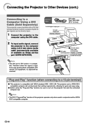
... a 15-pin terminal) I Before using a ø3.5 mm stereo audio cable (commercially available or available as Sharp service part QCNW-4870CEZZ). Connecting the Projector to Other Devices (cont.) Connecting to a Computer Using a DVI Cable (Sold Separately) This projector comes installed with a DVI digital input terminal in conjunction with VESA-standard DDC 1/DDC 2B. Optional...
... a 15-pin terminal) I Before using a ø3.5 mm stereo audio cable (commercially available or available as Sharp service part QCNW-4870CEZZ). Connecting the Projector to Other Devices (cont.) Connecting to a Computer Using a DVI Cable (Sold Separately) This projector comes installed with a DVI digital input terminal in conjunction with VESA-standard DDC 1/DDC 2B. Optional...

Operation Manual
Page 27
...-pin D-sub adaptor D-sub cable (sold separately) (sold separately) Note • When connecting the projector to the video equipment in this way, select "Component" for audio input. -23 nect the projector and the video equipment. 3 Connect the projector and the video equipment using the DVI to con- Setup and Connections Connecting to Video...
...-pin D-sub adaptor D-sub cable (sold separately) (sold separately) Note • When connecting the projector to the video equipment in this way, select "Component" for audio input. -23 nect the projector and the video equipment. 3 Connect the projector and the video equipment using the DVI to con- Setup and Connections Connecting to Video...

Operation Manual
Page 28
...) is required for audio input. For realizing a higher-quality image, use a commercially available S-VIDEO cable to connect the S-VIDEO terminal on the projector and the S-VIDEO output terminal on the video equipment. • A ø3.5 mm minijack to realize a higher-quality image. Connecting the... Projector to Other Devices (cont.) Connecting to Video Equipment Using an S-VIDEO, a Composite Video or an Audio Cable Using an S-VIDEO, video, or audio cable...
...) is required for audio input. For realizing a higher-quality image, use a commercially available S-VIDEO cable to connect the S-VIDEO terminal on the projector and the S-VIDEO output terminal on the video equipment. • A ø3.5 mm minijack to realize a higher-quality image. Connecting the... Projector to Other Devices (cont.) Connecting to Video Equipment Using an S-VIDEO, a Composite Video or an Audio Cable Using an S-VIDEO, video, or audio cable...


