Service Manual
Page 1
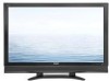
...maintaining the safety and performance of the set. REMOVING OF MAJOR PARTS [1] REMOVING OF MAJOR PARTS 4-1 Parts Guide CHAPTER 1. TopPage LC-60C52U SERVICE MANUAL No.SY6Y8LC60C52U LCD COLOR TELEVISION MODEL LC-60C52U In the interests of user-safety (Required by safety regulations in this Service Manual, accordingly, please refer to be used . ... be restored to its original condition and only parts identical to change without notice. OUTLINE This model is based on theLC-46D62U/LC-52D62U and partially modified. S86V8LC52D62U) Service Manual. This document has been published to the...
...maintaining the safety and performance of the set. REMOVING OF MAJOR PARTS [1] REMOVING OF MAJOR PARTS 4-1 Parts Guide CHAPTER 1. TopPage LC-60C52U SERVICE MANUAL No.SY6Y8LC60C52U LCD COLOR TELEVISION MODEL LC-60C52U In the interests of user-safety (Required by safety regulations in this Service Manual, accordingly, please refer to be used . ... be restored to its original condition and only parts identical to change without notice. OUTLINE This model is based on theLC-46D62U/LC-52D62U and partially modified. S86V8LC52D62U) Service Manual. This document has been published to the...
Service Manual
Page 2
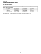
Description PRINTED WIRING BOARD ASSEMBLIES R/C, LED Unit KEY Unit MAIN Unit TERMINAL Unit POWER SUPPLY Unit LC-46D62U/LC-52D62U DUNTKD909FM02 DUNTKD910FM02 DUNTKD934FM02 DUNTKD935FM02 RDENCA184WJQZ LC-60C52U DUNTKD909FM02 DUNTKD910FM02 DUNTKD934FM08 DUNTKD935FM08 RDENCA184WJQZ Note No Changes No Changes No Changes No Changes No Changes Refer to the PARTS GUIDE for CABINET PARTS, SUPPLIED ACCESORIES, PACKING PARTS and SERVICE JIGS. LC-60C52U LLSMEDCCeaI-Dr-6F0v6kFCTi0e5EVcCt2e5UR2EMUaNnCuaElS FROM BASE MODEL LIST OF CHANGED PARTS Ref. No. i
Description PRINTED WIRING BOARD ASSEMBLIES R/C, LED Unit KEY Unit MAIN Unit TERMINAL Unit POWER SUPPLY Unit LC-46D62U/LC-52D62U DUNTKD909FM02 DUNTKD910FM02 DUNTKD934FM02 DUNTKD935FM02 RDENCA184WJQZ LC-60C52U DUNTKD909FM02 DUNTKD910FM02 DUNTKD934FM08 DUNTKD935FM08 RDENCA184WJQZ Note No Changes No Changes No Changes No Changes No Changes Refer to the PARTS GUIDE for CABINET PARTS, SUPPLIED ACCESORIES, PACKING PARTS and SERVICE JIGS. LC-60C52U LLSMEDCCeaI-Dr-6F0v6kFCTi0e5EVcCt2e5UR2EMUaNnCuaElS FROM BASE MODEL LIST OF CHANGED PARTS Ref. No. i
Service Manual
Page 3
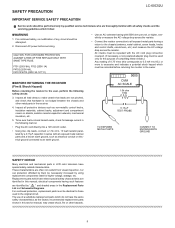
... per volt, or higher, sensitivity or measure the AC voltage drop across the resistor. LSCA-60FCE52TUY PRECAUTION Service Manual LC-60C52U IMPORTANT SERVICE SAFETY PRECAUTION Service work should be performed only by qualified service technicians who are thoroughly familiar with all lead... plug connection reversed. (If necessary, a non polarized adaptor plug must be necessarily increased by a 0.15µF capacitor in LCD color television have the same safety characteristics as non-metallic control knobs, insulation materials, cabinet backs, adjustment and compartment covers or shields...
... per volt, or higher, sensitivity or measure the AC voltage drop across the resistor. LSCA-60FCE52TUY PRECAUTION Service Manual LC-60C52U IMPORTANT SERVICE SAFETY PRECAUTION Service work should be performed only by qualified service technicians who are thoroughly familiar with all lead... plug connection reversed. (If necessary, a non polarized adaptor plug must be necessarily increased by a 0.15µF capacitor in LCD color television have the same safety characteristics as non-metallic control knobs, insulation materials, cabinet backs, adjustment and compartment covers or shields...
Service Manual
Page 5
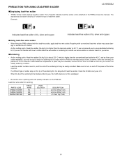
... lead wire solder by 40 °C, and as it has poor solder wettability, you confirm the steady soldering condition. PRECAUTION FOR USING LEAD-FREE SOLDER LC-60C52U „Employing lead-free solder • "PWBs" of it. The LF symbol indicates lead-free solder, and is alloyed with the lead-free solder, apply...
... lead wire solder by 40 °C, and as it has poor solder wettability, you confirm the steady soldering condition. PRECAUTION FOR USING LEAD-FREE SOLDER LC-60C52U „Employing lead-free solder • "PWBs" of it. The LF symbol indicates lead-free solder, and is alloyed with the lead-free solder, apply...
Service Manual
Page 6
SPECIFICATIONS [1] SPECIFICATIONS Service Manual 1 - 1 LC-60C52U LCC-H60AC52PUTER 1.
SPECIFICATIONS [1] SPECIFICATIONS Service Manual 1 - 1 LC-60C52U LCC-H60AC52PUTER 1.
Service Manual
Page 7
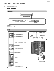
LCC-H60AC52PUTER 2. OPERATION MANUAL [1] OPERATION MANUAL Service Manual LC-60C52U 2 - 1
LCC-H60AC52PUTER 2. OPERATION MANUAL [1] OPERATION MANUAL Service Manual LC-60C52U 2 - 1
Service Manual
Page 10
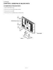
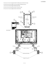
Remove the 4 lock screws 2 and detach the Stand. 3. Remove the 5 lock screws 3 . 4. Detach the SD Card Cover 1 . 2. Remove the 16 lock screws 4 and detach the Rear Cabinet. 4 SD Card Cover 1 3 3 2 2 Stand Rear Cabinet 4 - 1 REMOVING OF MAJOR PARTS [1] REMOVING OF MAJOR PARTS 1. LC-60C52U LLSMECCCea-HDr-60v6kACTi0e5VcCt2Pe5U2TMUEanRua4l.
Remove the 4 lock screws 2 and detach the Stand. 3. Remove the 5 lock screws 3 . 4. Detach the SD Card Cover 1 . 2. Remove the 16 lock screws 4 and detach the Rear Cabinet. 4 SD Card Cover 1 3 3 2 2 Stand Rear Cabinet 4 - 1 REMOVING OF MAJOR PARTS [1] REMOVING OF MAJOR PARTS 1. LC-60C52U LLSMECCCea-HDr-60v6kACTi0e5VcCt2Pe5U2TMUEanRua4l.
Service Manual
Page 11
Remove the 8 lock screws 7 and detach the Stand Fix Angle. 9. 5. Remove the 8 lock screws 6 8 lock point and detach the Stand St Cover-R. 7. Remove the 12 lock screws 5 and detach the Bridge Angle and Chassis Fix Angle. 6. Remove the 7 lock screws 8 and detach the Main Shield. 5 5 5 Bridge Angle Bridge Angle Chassis 8 Fix Angle 5 5 5 LC-60C52U Main Shield Hook 6 Stand Fix Angle 7 7 Stand Assist Holder Stand St Cover-R 4 - 2 Hook 6 Remove the 4 hook and detach the Stand assist Holder. 8.
Remove the 8 lock screws 7 and detach the Stand Fix Angle. 9. 5. Remove the 8 lock screws 6 8 lock point and detach the Stand St Cover-R. 7. Remove the 12 lock screws 5 and detach the Bridge Angle and Chassis Fix Angle. 6. Remove the 7 lock screws 8 and detach the Main Shield. 5 5 5 Bridge Angle Bridge Angle Chassis 8 Fix Angle 5 5 5 LC-60C52U Main Shield Hook 6 Stand Fix Angle 7 7 Stand Assist Holder Stand St Cover-R 4 - 2 Hook 6 Remove the 4 hook and detach the Stand assist Holder. 8.
Service Manual
Page 12
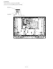
Top Cover Key PWB 䬌䎮䎰䬍 10 䬌䎵䎤䬍 䬌䎯䎤䬍 䬌䎵䎤䬍 4 - 3 LC-60C52U 10.Disconnect all the connectors from all the PWBs. 11.Remove the 2 lock screws 10 and detach the KEY PWB.
Top Cover Key PWB 䬌䎮䎰䬍 10 䬌䎵䎤䬍 䬌䎯䎤䬍 䬌䎵䎤䬍 4 - 3 LC-60C52U 10.Disconnect all the connectors from all the PWBs. 11.Remove the 2 lock screws 10 and detach the KEY PWB.
Service Manual
Page 13
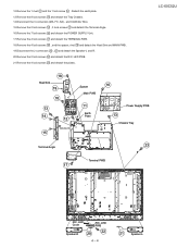
... detach the Speaker-L and R. 20.Remove the 2 lock screws 22 and detach the R/C, LED PWB. 21.Remove the 4 lock screws 23 and detach the plates. LC-60C52U 18 Heat Sink 19 18 Spacer Main PWB 13 14 MA FC SA 12 11 Earth Plate COAXIAL Wire 15 16 Power Supply PWB 13...
... detach the Speaker-L and R. 20.Remove the 2 lock screws 22 and detach the R/C, LED PWB. 21.Remove the 4 lock screws 23 and detach the plates. LC-60C52U 18 Heat Sink 19 18 Spacer Main PWB 13 14 MA FC SA 12 11 Earth Plate COAXIAL Wire 15 16 Power Supply PWB 13...
Service Manual
Page 14
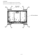
LC-60C52U 22.Remove the 4 lock screws 24 and detach the LCD Panel Module. 23.Remove the 8 lock screws 25 and detach the Chassis Fix Angle T/B. 25 24 Chassis Fix Angle T/B 24 25 LCD Panel Module 25 24 25 24 4 - 5
LC-60C52U 22.Remove the 4 lock screws 24 and detach the LCD Panel Module. 23.Remove the 8 lock screws 25 and detach the Chassis Fix Angle T/B. 25 24 Chassis Fix Angle T/B 24 25 LCD Panel Module 25 24 25 24 4 - 5
Service Manual
Page 15
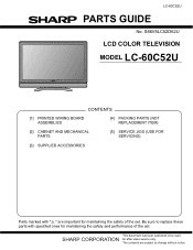
S86V8LC52D62U LCD COLOR TELEVISION MODEL LC-60C52U CONTENTS [1] PRINTED WIRING BOARD ASSEMBLIES [4] PACKING PARTS (NOT REPLACEMENT ITEM) [2] CABINET AND MECHANICAL PARTS [5] SERVICE JIGS (USE FOR SERVICING) [3] SUPPLIED ACCESSORIES Parts marked with specified ones for after sales service only. The contents are important for maintaining the safety of the set . PartsGuide LC-60C52U PARTS GUIDE No. This...
S86V8LC52D62U LCD COLOR TELEVISION MODEL LC-60C52U CONTENTS [1] PRINTED WIRING BOARD ASSEMBLIES [4] PACKING PARTS (NOT REPLACEMENT ITEM) [2] CABINET AND MECHANICAL PARTS [5] SERVICE JIGS (USE FOR SERVICING) [3] SUPPLIED ACCESSORIES Parts marked with specified ones for after sales service only. The contents are important for maintaining the safety of the set . PartsGuide LC-60C52U PARTS GUIDE No. This...
Service Manual
Page 18
N - AC AF AD - LED Cover X Badge, "SHARP" - Corner Cover, x4 X SP Net - Screw (for Stand Ass'y), x6 - N AG - S BC N - N...36 37 38 39 40 41 42 43 44 45 46 47 48 50 51 52 53 54 56 58 59 60 61 62 63 64 65 66 67 CCABAB524WJ01 ...(for Stand), x4 DESCRIPTION 4 N - Control Button X Stand Ass'y X Stand Base Ass'y X Stand Support Ass'y, x2 X 52V LCD Panel Module Unit X R/C, LED Unit X Key Unit R Main Unit X Terminal Unit X Power Unit X SD COVER X Stand St ...(R) X Speaker (L) X Screw, x36 X Screw, x35 X Screw, x2 X Screw, x3 X Screw, x4 X Screw, x16 - LC-60C52U NO. AA -
N - AC AF AD - LED Cover X Badge, "SHARP" - Corner Cover, x4 X SP Net - Screw (for Stand Ass'y), x6 - N AG - S BC N - N...36 37 38 39 40 41 42 43 44 45 46 47 48 50 51 52 53 54 56 58 59 60 61 62 63 64 65 66 67 CCABAB524WJ01 ...(for Stand), x4 DESCRIPTION 4 N - Control Button X Stand Ass'y X Stand Base Ass'y X Stand Support Ass'y, x2 X 52V LCD Panel Module Unit X R/C, LED Unit X Key Unit R Main Unit X Terminal Unit X Power Unit X SD COVER X Stand St ...(R) X Speaker (L) X Screw, x36 X Screw, x35 X Screw, x2 X Screw, x3 X Screw, x4 X Screw, x16 - LC-60C52U NO. AA -
Service Manual
Page 21
... AP N QCNW-F137WJQZ AX N QCNW-F138WJQZ AP N QCNW-F139WJQZ AX J 80pins FFC L=1000mm Pitch=0.5mm, x2used, LCD Contr J RCA Cable L=1500mm, Tuner Extension J 41pins L=400mm (LV) J L=1000mm (LV) J L=1000mm (LB) J L=1000mm (LP) J L=1000mm (SP) J L=1000mm (RA) LC-60C52U 7 N - - Label Top Pad Packing Add. N - - No. N - - - - - - NO. N - [5] SERVICE JIGS (USE FOR SERVICING) Packing Case Bottom...
... AP N QCNW-F137WJQZ AX N QCNW-F138WJQZ AP N QCNW-F139WJQZ AX J 80pins FFC L=1000mm Pitch=0.5mm, x2used, LCD Contr J RCA Cable L=1500mm, Tuner Extension J 41pins L=400mm (LV) J L=1000mm (LV) J L=1000mm (LB) J L=1000mm (LP) J L=1000mm (SP) J L=1000mm (RA) LC-60C52U 7 N - - Label Top Pad Packing Add. N - - No. N - - - - - - NO. N - [5] SERVICE JIGS (USE FOR SERVICING) Packing Case Bottom...
Service Manual
Page 22
Jan. 2007 Printed in any from or by any means, electronic, mechanical, photocopying, recording, orotherwise, without prior written permission of the publisher. LC-60C52U COPYRIGHT © 2007 BY SHARP CORPORATION ALL RIGHTS RESERVED. KG SHARP CORPORATION AV Systems Group CS PromotionCenter Yaita,Tochigi 329-2193, Japan No Part of this publication may be reproduced, stored in a retrieval system, ortransmitted in Japan TQ2096-S SY.
Jan. 2007 Printed in any from or by any means, electronic, mechanical, photocopying, recording, orotherwise, without prior written permission of the publisher. LC-60C52U COPYRIGHT © 2007 BY SHARP CORPORATION ALL RIGHTS RESERVED. KG SHARP CORPORATION AV Systems Group CS PromotionCenter Yaita,Tochigi 329-2193, Japan No Part of this publication may be reproduced, stored in a retrieval system, ortransmitted in Japan TQ2096-S SY.


