
Service Manual
Page 1
... should be used . DIMENSIONS [1] DIMENSIONS 3-1 CHAPTER 4. The contents are important for maintaining the safety of the set . OPERATION MANUAL [1] OPERATION MANUAL 2-1 CHAPTER 3. CONTENTS DIFFERENCES FROM BASE MODEL LIST OF CHANGED PARTS i Parts Guide SAFETY PRECAUTION IMPORTANT SERVICE SAFETY PRECAUTION ii PRECAUTIONS A PRENDRE LORS DE LA REPARATION iii PRECAUTIONS FOR USING LEAD-FREE SOLDER iv CHAPTER 1. REMOVING OF MAJOR PARTS [1] REMOVING OF MAJOR PARTS 4-1 Parts marked with specified ones for after sales service only. SPECIFICATIONS [1] SPECIFICATIONS...
... should be used . DIMENSIONS [1] DIMENSIONS 3-1 CHAPTER 4. The contents are important for maintaining the safety of the set . OPERATION MANUAL [1] OPERATION MANUAL 2-1 CHAPTER 3. CONTENTS DIFFERENCES FROM BASE MODEL LIST OF CHANGED PARTS i Parts Guide SAFETY PRECAUTION IMPORTANT SERVICE SAFETY PRECAUTION ii PRECAUTIONS A PRENDRE LORS DE LA REPARATION iii PRECAUTIONS FOR USING LEAD-FREE SOLDER iv CHAPTER 1. REMOVING OF MAJOR PARTS [1] REMOVING OF MAJOR PARTS 4-1 Parts marked with specified ones for after sales service only. SPECIFICATIONS [1] SPECIFICATIONS...
Service Manual
Page 2
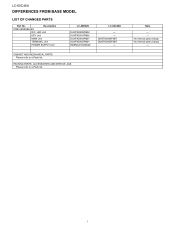
Note - - i No Internal parts change No Internal parts change - PACKING PARTS, ACCESSORIES AND SERVICE JIGS Please refer to a Parts list. LC-60C46U LDCI-6F0FC4E6URENCES FROM BASE MODEL Service Manual LIST OF CHANGED PARTS Ref. Description PWB ASSEMBLIES R/C, LED Unit KEY Unit MAIN Unit TERMINAL Unit POWER SUPPLY Unit LC-46D62U DUNTKD909FM02 DUNTKD910FM02 DUNTKD934FM01 DUNTKD935FM01 RDENCA184WJQZ LC-60C46U ← ← DUNTKD934FM07 DUNTKD935FM07 ← CABINET AND MECHANICAL PARTS Please refer to a Parts list. No.
Note - - i No Internal parts change No Internal parts change - PACKING PARTS, ACCESSORIES AND SERVICE JIGS Please refer to a Parts list. LC-60C46U LDCI-6F0FC4E6URENCES FROM BASE MODEL Service Manual LIST OF CHANGED PARTS Ref. Description PWB ASSEMBLIES R/C, LED Unit KEY Unit MAIN Unit TERMINAL Unit POWER SUPPLY Unit LC-46D62U DUNTKD909FM02 DUNTKD910FM02 DUNTKD934FM01 DUNTKD935FM01 RDENCA184WJQZ LC-60C46U ← ← DUNTKD934FM07 DUNTKD935FM07 ← CABINET AND MECHANICAL PARTS Please refer to a Parts list. No.
Service Manual
Page 3
... AC power before returning the monitor to the owner. „BEFORE RETURNING THE RECEIVER (Fire & Shock Hazard) Before returning the receiver to those used only for the purpose of 0.75 Vrms (this service manual, may create shock, fire or other metal parts in this manual; TO EXPOSED METAL PARTS CONNECT TO KNOWN EARTH GROUND SAFETY NOTICE Many electrical and mechanical parts in LCD color television have...
... AC power before returning the monitor to the owner. „BEFORE RETURNING THE RECEIVER (Fire & Shock Hazard) Before returning the receiver to those used only for the purpose of 0.75 Vrms (this service manual, may create shock, fire or other metal parts in this manual; TO EXPOSED METAL PARTS CONNECT TO KNOWN EARTH GROUND SAFETY NOTICE Many electrical and mechanical parts in LCD color television have...
Service Manual
Page 5
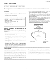
... as soon as required. Clean the bit after every use , file it . Make sure to cracks. PRECAUTIONS FOR USING LEAD-FREE SOLDER LC-60C46U „Employing lead-free solder • "PWBs" of the soldering bit is attached on the PWB silk. When the tip of this model employs lead-free solder. Repairing with polarity indication on the PWBs and service manuals.
... as soon as required. Clean the bit after every use , file it . Make sure to cracks. PRECAUTIONS FOR USING LEAD-FREE SOLDER LC-60C46U „Employing lead-free solder • "PWBs" of the soldering bit is attached on the PWB silk. When the tip of this model employs lead-free solder. Repairing with polarity indication on the PWBs and service manuals.
Service Manual
Page 6
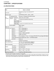
.... SPECIFICATIONS [1] SPECIFICATIONS Service Manual Item Model: LC-60C46U LCD panel 46" Advanced Super View & BLACK TFT LCD Number of dots 6,220,800 dots (1920 1080 3 dots) TV Function TV-standard (CCIR) Receiving VHF/UHF Channel CATV American TV Standard ATSC/NTSC System VHF 2-13ch, UHF 14-69ch 1-135ch (non-scrambled channel only) Digital Terrestrial Broadcast (8VSB) 2-69ch Digital cable*1 (64/256 QAM) 1-135ch (non-scrambled channel only) Audio multiplex BTSC System Audio...
.... SPECIFICATIONS [1] SPECIFICATIONS Service Manual Item Model: LC-60C46U LCD panel 46" Advanced Super View & BLACK TFT LCD Number of dots 6,220,800 dots (1920 1080 3 dots) TV Function TV-standard (CCIR) Receiving VHF/UHF Channel CATV American TV Standard ATSC/NTSC System VHF 2-13ch, UHF 14-69ch 1-135ch (non-scrambled channel only) Digital Terrestrial Broadcast (8VSB) 2-69ch Digital cable*1 (64/256 QAM) 1-135ch (non-scrambled channel only) Audio multiplex BTSC System Audio...
Service Manual
Page 7
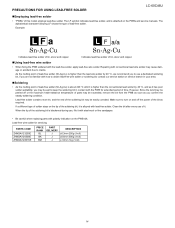
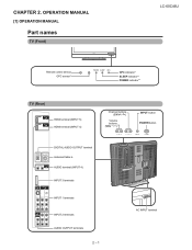
LCC-H60AC46PUTER 2. OPERATION MANUAL [1] OPERATION MANUAL Part names TV (Front) Service Manual LC-60C46U Remote control sensor OPC sensor* OPC indicator* SLEEP indicator** POWER indicator** TV (Rear) HDMI terminal (INPUT 5) HDMI terminal (INPUT 4) Channel buttons (CH / ) Volume buttons (VOL - / + ) INPUT button POWER button DIGITAL AUDIO OUTPUT terminal Antenna/Cable in AUDIO terminal (INPUT 4) INPUT 3 terminals INPUT 1 terminals INPUT 2 terminals AUDIO OUTPUT terminals 2 - 1 AC INPUT terminal
LCC-H60AC46PUTER 2. OPERATION MANUAL [1] OPERATION MANUAL Part names TV (Front) Service Manual LC-60C46U Remote control sensor OPC sensor* OPC indicator* SLEEP indicator** POWER indicator** TV (Rear) HDMI terminal (INPUT 5) HDMI terminal (INPUT 4) Channel buttons (CH / ) Volume buttons (VOL - / + ) INPUT button POWER button DIGITAL AUDIO OUTPUT terminal Antenna/Cable in AUDIO terminal (INPUT 4) INPUT 3 terminals INPUT 1 terminals INPUT 2 terminals AUDIO OUTPUT terminals 2 - 1 AC INPUT terminal
Service Manual
Page 8
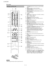
... power of the external equipment on and off the menu screen. 12 SLEEP: Set the sleep timer. 13 AUDIO: Selects the MTS/SAP or the audio mode during multi-channel audio broadcasts. 14 FUNCTION: Switches the remote control for TV, CBL/ 17 SAT, VCR, DVD and AUDIO operation. The lighting will light. Press again to return to press FUNCTION and DISPLAY at the TV. 2 - 2 This 20 button is TV, INPUT 1, 2 or 3: STANDARD, MOVIE, GAME, USER, DYNAMIC (Fixed...
... power of the external equipment on and off the menu screen. 12 SLEEP: Set the sleep timer. 13 AUDIO: Selects the MTS/SAP or the audio mode during multi-channel audio broadcasts. 14 FUNCTION: Switches the remote control for TV, CBL/ 17 SAT, VCR, DVD and AUDIO operation. The lighting will light. Press again to return to press FUNCTION and DISPLAY at the TV. 2 - 2 This 20 button is TV, INPUT 1, 2 or 3: STANDARD, MOVIE, GAME, USER, DYNAMIC (Fixed...
Service Manual
Page 10
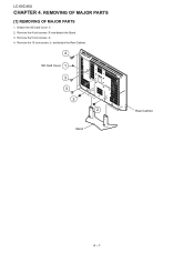
Detach the SD Card Cover . 2. Remove the 13 lock screws and detach the Rear Cabinet. 4 SD Card Cover 1 3 3 2 2 Rear Cabinet Stand 4 - 1 REMOVING OF MAJOR PARSTeSrvice Manual [1] REMOVING OF MAJOR PARTS 1. Remove the 5 lock screws . 4. LC-60C46U LCC-H60AC46PUTER 4. Remove the 4 lock screws and detach the Stand. 3.
Detach the SD Card Cover . 2. Remove the 13 lock screws and detach the Rear Cabinet. 4 SD Card Cover 1 3 3 2 2 Rear Cabinet Stand 4 - 1 REMOVING OF MAJOR PARSTeSrvice Manual [1] REMOVING OF MAJOR PARTS 1. Remove the 5 lock screws . 4. LC-60C46U LCC-H60AC46PUTER 4. Remove the 4 lock screws and detach the Stand. 3.
Service Manual
Page 11
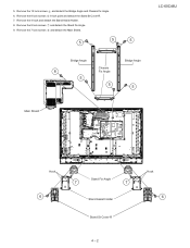
Remove the 4 hook and detach the Stand Assist Holder. 8. Remove the 7 lock screws and detach the Main Shield. 5 5 5 Bridge Angle Bridge Angle Chassis 8 Fix Angle 5 5 5 LC-60C46U Main Shield Hook 6 Stand Fix Angle 7 7 Stand Assist Holder Stand St Cover-R Hook 6 4 - 2 Remove the 8 lock screws 8 lock point and detach the Stand St Cover-R. 7. 5. Remove the 12 lock screws and detach the Bridge Angle and Chassis Fix Angle. 6. Remove the 8 lock screws and detach the Stand Fix Angle. 9.
Remove the 4 hook and detach the Stand Assist Holder. 8. Remove the 7 lock screws and detach the Main Shield. 5 5 5 Bridge Angle Bridge Angle Chassis 8 Fix Angle 5 5 5 LC-60C46U Main Shield Hook 6 Stand Fix Angle 7 7 Stand Assist Holder Stand St Cover-R Hook 6 4 - 2 Remove the 8 lock screws 8 lock point and detach the Stand St Cover-R. 7. 5. Remove the 12 lock screws and detach the Bridge Angle and Chassis Fix Angle. 6. Remove the 8 lock screws and detach the Stand Fix Angle. 9.
Service Manual
Page 12
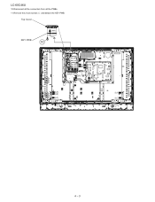
Top Cover KEY PWB [KM] 10 [KM] [LB] [PH] [PD] [MA][FC] [SA] [SP] [RA] [PD] [PH] [LA] [LA] [LA] [LB] [LC] [LC] [RA] 4 - 3 LC-60C46U 10.Disconnect all the connectors from all the PWBs. 11.Remove the 2 lock screws and detach the KEY PWB.
Top Cover KEY PWB [KM] 10 [KM] [LB] [PH] [PD] [MA][FC] [SA] [SP] [RA] [PD] [PH] [LA] [LA] [LA] [LB] [LC] [LC] [RA] 4 - 3 LC-60C46U 10.Disconnect all the connectors from all the PWBs. 11.Remove the 2 lock screws and detach the KEY PWB.
Service Manual
Page 13
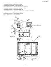
... Angle. 16.Remove the 7 lock screws and detach the POWER SUPPLY PWB. 17.Remove the 4 lock screws and detach the TERMINAL PWB. 18.Remove the 4 lock screws , and the spacer, rivet and detach the Heat Sink and MAIN PWB. 19.Disconnect the 2 connectors , and detach the Speaker-L and R. 20.Remove the 2 lock screws and detach the R/C, LED PWB. 21.Remove the 4 lock screws and detach the plates. LC-60C46U 17 Heat...
... Angle. 16.Remove the 7 lock screws and detach the POWER SUPPLY PWB. 17.Remove the 4 lock screws and detach the TERMINAL PWB. 18.Remove the 4 lock screws , and the spacer, rivet and detach the Heat Sink and MAIN PWB. 19.Disconnect the 2 connectors , and detach the Speaker-L and R. 20.Remove the 2 lock screws and detach the R/C, LED PWB. 21.Remove the 4 lock screws and detach the plates. LC-60C46U 17 Heat...
Service Manual
Page 14
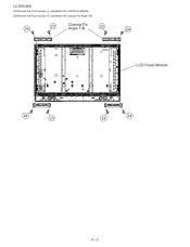
and detach the Chassis Fix Angle T/B. 24 23 Chassis Fix Angle T/B 23 24 LCD Panel Module 24 23 24 23 4 - 5 LC-60C46U 22.Remove the 4 lock screws 23.Remove the 8 lock screws and detach the LCD Panel Module.
and detach the Chassis Fix Angle T/B. 24 23 Chassis Fix Angle T/B 23 24 LCD Panel Module 24 23 24 23 4 - 5 LC-60C46U 22.Remove the 4 lock screws 23.Remove the 8 lock screws and detach the LCD Panel Module.
Service Manual
Page 15
... change without notice. Be sure to be used for after sales service only. This document has been published to replace these parts with " " are important for maintaining the safety and performance of the set . The contents are arranged in alphabetical order. PartsGuide LC-60C46U PARTS GUIDE No. MODEL LC-60C46U CONTENTS [1] PRINTED WIRING BOARD ASSEMBLIES [4] PACKING PARTS (NOT REPLACEMENT ITEM) [2] CABINET AND MECHANICAL PARTS [5] SERVICE JIG (USE FOR SERVICING) [3] SUPPLIED ACCESSORIES Parts...
... change without notice. Be sure to be used for after sales service only. This document has been published to replace these parts with " " are important for maintaining the safety and performance of the set . The contents are arranged in alphabetical order. PartsGuide LC-60C46U PARTS GUIDE No. MODEL LC-60C46U CONTENTS [1] PRINTED WIRING BOARD ASSEMBLIES [4] PACKING PARTS (NOT REPLACEMENT ITEM) [2] CABINET AND MECHANICAL PARTS [5] SERVICE JIG (USE FOR SERVICING) [3] SUPPLIED ACCESSORIES Parts...

Service Manual
Page 18
...) X Connecting Cord (LA) X Earth Plate X Printed Wiring Board (LV) X Speaker (Right) X Speaker (Left) X Screw for Angle Fix, x28 X Screw for Angle, x35 X Screw for HDMI, x2 X Screw for Jack, x3 X Screw, x4 X Screw for Stand Ass'y, x6 - N BB N N AA - AC AF AD - - N GC AQ AH CQ N BG N BU AG AD AD AF AH AH N AP AK BB - N AB AK BA - LED Cover X Badge, "SHARP" - Control Button X 46"LCD Panel...
...) X Connecting Cord (LA) X Earth Plate X Printed Wiring Board (LV) X Speaker (Right) X Speaker (Left) X Screw for Angle Fix, x28 X Screw for Angle, x35 X Screw for HDMI, x2 X Screw for Jack, x3 X Screw, x4 X Screw for Stand Ass'y, x6 - N BB N N AA - AC AF AD - - N GC AQ AH CQ N BG N BU AG AD AD AF AH AH N AP AK BB - N AB AK BA - LED Cover X Badge, "SHARP" - Control Button X 46"LCD Panel...
Service Manual
Page 21
... Cable L=1500mm, Tuner Extension J 41pins L=400mm, Main Unit to LCD Controller Unit (LV) J 6pins-3pins/3pins L=1000mm, Power Unit (LA) to Inv-2 (LA1) / Inv-4 (LA2) J 4pins-9pins L=1000mm, Main Unit to Inv-2 Unit (LB) J 20pins L=1000mm, Main Unit to LCD Controller (LP) J 4pins-2pins/2pins L=1000mm, Terminal Unit to Speaker-R / Speaker-L (SP) J 13pins L=1000mm, Terminal Unit to R/C LED Unit (RA) LC-60C46U...
... Cable L=1500mm, Tuner Extension J 41pins L=400mm, Main Unit to LCD Controller Unit (LV) J 6pins-3pins/3pins L=1000mm, Power Unit (LA) to Inv-2 (LA1) / Inv-4 (LA2) J 4pins-9pins L=1000mm, Main Unit to Inv-2 Unit (LB) J 20pins L=1000mm, Main Unit to LCD Controller (LP) J 4pins-2pins/2pins L=1000mm, Terminal Unit to Speaker-R / Speaker-L (SP) J 13pins L=1000mm, Terminal Unit to R/C LED Unit (RA) LC-60C46U...
Service Manual
Page 23
... SUPPLEMENT LCD COLOR TELEVISION LC-46D62U MODELS LC-60C46U LC-60C46U In the interests of the set. OUTLINE In this Service Manual, only parts in some countries) the set . This document has been published to those specified should be used . For the other points, refer to change without notice. Be sure to replace these parts with " " are subject to the LC-46D62U/LC60C46U (S86V8LC52D62U/S17B3LC60C46U) Service Manual. TopPage LC-46D62U LC-46D62U/LC-60C46U SERVICE MANUAL No...
... SUPPLEMENT LCD COLOR TELEVISION LC-46D62U MODELS LC-60C46U LC-60C46U In the interests of the set. OUTLINE In this Service Manual, only parts in some countries) the set . This document has been published to those specified should be used . For the other points, refer to change without notice. Be sure to replace these parts with " " are subject to the LC-46D62U/LC60C46U (S86V8LC52D62U/S17B3LC60C46U) Service Manual. TopPage LC-46D62U LC-46D62U/LC-60C46U SERVICE MANUAL No...
Service Manual
Page 24
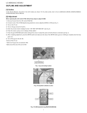
LC-46D62U/LC-60C46U LOCU-46TDL62IUNE AND ADJUSTMENT Service Manual [1] Outline In this Service Manual, only parts in the LCD module are shown. For the other points, refer to the LC-46D62U/LC-60C46U (S86V8LC52D62U/ S17B3LC60C46U) Service Manual. [2] Adjustment When replacing the LCD control PCB, follow these steps to adjust VCOM. 1) Remove the wire from the LCD control PCB CN3. 2) Connect a wire of the VCOM adjustment jig (electronic volume adjustment BOX) to CN3 (see Fig. 1). 3) Turn on the TV set. 4) Turn on...
LC-46D62U/LC-60C46U LOCU-46TDL62IUNE AND ADJUSTMENT Service Manual [1] Outline In this Service Manual, only parts in the LCD module are shown. For the other points, refer to the LC-46D62U/LC-60C46U (S86V8LC52D62U/ S17B3LC60C46U) Service Manual. [2] Adjustment When replacing the LCD control PCB, follow these steps to adjust VCOM. 1) Remove the wire from the LCD control PCB CN3. 2) Connect a wire of the VCOM adjustment jig (electronic volume adjustment BOX) to CN3 (see Fig. 1). 3) Turn on the TV set. 4) Turn on...
Service Manual
Page 25
PartsGuide LC-46D62U/LC-60C46U PARTS GUIDE No. Be sure to replace these parts with " " are subject to be used for maintaining the safety of the set . The contents are important for after sales service only. S37D1LC46D62U LCD COLOR TELEVISION LC-46D62U LC-46D62U MODELS LC-60C46U LC-60C46U CONTENTS [1] LCD MODULE Assembly Parts marked with specified ones for maintaining the safety and performance of the set . This document has been published to change without notice.
PartsGuide LC-46D62U/LC-60C46U PARTS GUIDE No. Be sure to replace these parts with " " are subject to be used for maintaining the safety of the set . The contents are important for after sales service only. S37D1LC46D62U LCD COLOR TELEVISION LC-46D62U LC-46D62U MODELS LC-60C46U LC-60C46U CONTENTS [1] LCD MODULE Assembly Parts marked with specified ones for maintaining the safety and performance of the set . This document has been published to change without notice.
Service Manual
Page 27
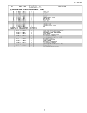
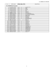
LC-46D62U/LC-60C46U NO. PARTS CODE PRICE NEW PART RANK MARK DELIVERY DESCRIPTION [1] LCD MODULE Assembly 1 5 6 7 8 9 10 11 12 13 14 15 17 18 19 20 21 22 23 24 27-1 27-2 27-3 27-4 27-5 27-6 27...N BD N AS N AQ N AQ N AA J LCD Module Ass'y J Frame J Frame J Plate, x2 J Clip, x6 J Clip J Screw, x10 J Screw, x8 J CS-FPC1, x2 J LCD CONTROL Unit J Cover (LCD Control Unit (Top)) J Cover (LCD Control Unit (Bottom)) J Diffusion Panel J Diffusion Sheet J Prism Sheet J Optical Sheet J Sheet Holder Ass'y, x2 J Sheet Holder Ass'y, x2 J Screw, x10 J Screw, x5 J Chassis Ass'y J Lamp clip, x10 J ...
LC-46D62U/LC-60C46U NO. PARTS CODE PRICE NEW PART RANK MARK DELIVERY DESCRIPTION [1] LCD MODULE Assembly 1 5 6 7 8 9 10 11 12 13 14 15 17 18 19 20 21 22 23 24 27-1 27-2 27-3 27-4 27-5 27-6 27...N BD N AS N AQ N AQ N AA J LCD Module Ass'y J Frame J Frame J Plate, x2 J Clip, x6 J Clip J Screw, x10 J Screw, x8 J CS-FPC1, x2 J LCD CONTROL Unit J Cover (LCD Control Unit (Top)) J Cover (LCD Control Unit (Bottom)) J Diffusion Panel J Diffusion Sheet J Prism Sheet J Optical Sheet J Sheet Holder Ass'y, x2 J Sheet Holder Ass'y, x2 J Screw, x10 J Screw, x5 J Chassis Ass'y J Lamp clip, x10 J ...
Service Manual
Page 28
TQ2178-S YT. No Part of this publication may be reproduced, stored in a retrieval system, or transmitted in any from or by any means, electronic, mechanical, photocopying, recording, or otherwise, without prior written permission of the publisher. DS SHARP CORPORATION AV Systems Group CS Promotion Center Yaita,Tochigi 329-2193, Japan LC-46D62U/LC-60C46U COPYRIGHT © 2007 BY SHARP CORPORATION ALL RIGHTS RESERVED.
TQ2178-S YT. No Part of this publication may be reproduced, stored in a retrieval system, or transmitted in any from or by any means, electronic, mechanical, photocopying, recording, or otherwise, without prior written permission of the publisher. DS SHARP CORPORATION AV Systems Group CS Promotion Center Yaita,Tochigi 329-2193, Japan LC-46D62U/LC-60C46U COPYRIGHT © 2007 BY SHARP CORPORATION ALL RIGHTS RESERVED.


