
Service Manual
Page 1
...-28SP2 SERVICE MANUAL SY0M5LC-28HM2 LCD AV MONITOR Side Speakers (Option) LC-28HM2 (E/H/M) MODEL AN-28SP2 In the interests of user-safety (Required by safety regulations in some countries) the set should be restored to its original condition and only parts identical to those specified should be used. CONTENTS Page » IMPORTANT SERVICE SAFETY PRECAUTION ..... 2 » SPECIFICATIONS 3 » OPERATION MANUAL 4 » DIMENSIONS 7 » REMOVING OF MAJOR PARTS 9 » POWER SUPPLY...
...-28SP2 SERVICE MANUAL SY0M5LC-28HM2 LCD AV MONITOR Side Speakers (Option) LC-28HM2 (E/H/M) MODEL AN-28SP2 In the interests of user-safety (Required by safety regulations in some countries) the set should be restored to its original condition and only parts identical to those specified should be used. CONTENTS Page » IMPORTANT SERVICE SAFETY PRECAUTION ..... 2 » SPECIFICATIONS 3 » OPERATION MANUAL 4 » DIMENSIONS 7 » REMOVING OF MAJOR PARTS 9 » POWER SUPPLY...
Service Manual
Page 2
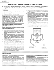
... and mechanical parts in LCD television and shaded areas in series with all protective devices such as the factory Replacement parts which do not rated for this manual; necessarily increased by using replacement components The use an isolation ...manual, may create shock, fire or other metal parts in the receiver. DVM 2. CAUTION: FOR CONTINUED PROTECTION AGAINST A RISK OF FIRE REPLACE ONLY WITH SAME TYPE FUSE. BEFORE RETURNING THE RECEIVER (Fire & Shock Hazard) » Use an AC voltmeter having a return to the chassis (antenna, metal cabinet, screw heads, knobs and control...
... and mechanical parts in LCD television and shaded areas in series with all protective devices such as the factory Replacement parts which do not rated for this manual; necessarily increased by using replacement components The use an isolation ...manual, may create shock, fire or other metal parts in the receiver. DVM 2. CAUTION: FOR CONTINUED PROTECTION AGAINST A RISK OF FIRE REPLACE ONLY WITH SAME TYPE FUSE. BEFORE RETURNING THE RECEIVER (Fire & Shock Hazard) » Use an AC voltmeter having a return to the chassis (antenna, metal cabinet, screw heads, knobs and control...

Service Manual
Page 3
... for AC power cord AVC system: Display output 26 pins System link AV input1 S-video, Video, Audio; Recommendable optional speaker Bose System side speakers; 25W (12.5W+12.5W) INTERFACES (TERMINALS) Display: Display input 26 pins System link Speaker terminals For BOSE System side speaker Power Inlet for Component input PC capability VGA/SVGA/XGA WIDE view mode STRETCH/FULL AUTO wide view (NTSC picture only) Automatically fully stretched POWER SUPPLY AC auto power voltage capability...
... for AC power cord AVC system: Display output 26 pins System link AV input1 S-video, Video, Audio; Recommendable optional speaker Bose System side speakers; 25W (12.5W+12.5W) INTERFACES (TERMINALS) Display: Display input 26 pins System link Speaker terminals For BOSE System side speaker Power Inlet for Component input PC capability VGA/SVGA/XGA WIDE view mode STRETCH/FULL AUTO wide view (NTSC picture only) Automatically fully stretched POWER SUPPLY AC auto power voltage capability...

Service Manual
Page 4
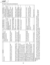
VOL + INPUT BRIGHTNESS MAIN POWER INPUT button MAIN POWER switch VOL (+)/(-) button BRIGHTNESS button Front view Table stand Remote sensor window Rear view AC power input terminal System cable cover Back cover Side speakers (Option) POWER/Standby indicator Display input terminal Speaker cable connection terminals for the optional side speakers 4 LC-28HM2 AN-28SP2 Operation Manual Display Top view -
VOL + INPUT BRIGHTNESS MAIN POWER INPUT button MAIN POWER switch VOL (+)/(-) button BRIGHTNESS button Front view Table stand Remote sensor window Rear view AC power input terminal System cable cover Back cover Side speakers (Option) POWER/Standby indicator Display input terminal Speaker cable connection terminals for the optional side speakers 4 LC-28HM2 AN-28SP2 Operation Manual Display Top view -

Service Manual
Page 6
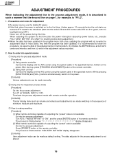
... an input source to which external equipment is not connected. LCD MONITOR Remote Control 6 The POWER/Standby indicator lights up green. w Cursor buttons Use these buttons to turn off the sound. MENU ENTER 5 COMPONENT buttons 0 Use these buttons to select an AV input terminal 8 directly. • You can be adjusted in the range 0~60. 0 MENU button Use this button once more. POWER INPUT AV INPUT 1 2 3 COMPONENT PC 1 2 MUTE VOL 3 INPUT button Use this button to temporarily turn on , press this button to increase/decrease sound volume. LC...
... an input source to which external equipment is not connected. LCD MONITOR Remote Control 6 The POWER/Standby indicator lights up green. w Cursor buttons Use these buttons to turn off the sound. MENU ENTER 5 COMPONENT buttons 0 Use these buttons to select an AV input terminal 8 directly. • You can be adjusted in the range 0~60. 0 MENU button Use this button once more. POWER INPUT AV INPUT 1 2 3 COMPONENT PC 1 2 MUTE VOL 3 INPUT button Use this button to temporarily turn on , press this button to increase/decrease sound volume. LC...

Service Manual
Page 13
.... (1) Selection of analog video input signal of 2 systems (2) Enlargement, reduction (including wide angle processing) and complement of video signals (3) Production of signals required for the display in the steps to follow (4) Synthesis of OSD (channel call, menu, etc) (5) Encoding of the prepared video signal and timing signal for output (6) Control of external devices (video adjustment, video source selection, power supply, etc) (Same as ordinary microprocessor) (7) Storage of information such as adjustment data Program data and...
.... (1) Selection of analog video input signal of 2 systems (2) Enlargement, reduction (including wide angle processing) and complement of video signals (3) Production of signals required for the display in the steps to follow (4) Synthesis of OSD (channel call, menu, etc) (5) Encoding of the prepared video signal and timing signal for output (6) Control of external devices (video adjustment, video source selection, power supply, etc) (Same as ordinary microprocessor) (7) Storage of information such as adjustment data Program data and...
Service Manual
Page 14
... times of the decoder IC. Cautions: » With this case, start -up with such trouble as left. When the power is switched on, the display unit's power relay is turned on, but it is turned off immediately. Panel side decoder IC. Countermeasure Replace cable or connector and check connection. No OSD appearing (Remote control is not fed into the panel control G/A (Detected by display button operation while keeping connection between signal...
... times of the decoder IC. Cautions: » With this case, start -up with such trouble as left. When the power is switched on, the display unit's power relay is turned on, but it is turned off immediately. Panel side decoder IC. Countermeasure Replace cable or connector and check connection. No OSD appearing (Remote control is not fed into the panel control G/A (Detected by display button operation while keeping connection between signal...

Service Manual
Page 15
... (P2001_5). 3 After resetting the display microprocessor, +5V output is present at SMPOW (J4001_22). (At the same time, the power is supplied to each line.) 5 After the AVC system unit has been initialized, the backlight illumination command is emitted to each line.) 4 Main power relay switch is turned on at AVC system unit » System cable connection tying the Display unit and the...
... (P2001_5). 3 After resetting the display microprocessor, +5V output is present at SMPOW (J4001_22). (At the same time, the power is supplied to each line.) 5 After the AVC system unit has been initialized, the backlight illumination command is emitted to each line.) 4 Main power relay switch is turned on at AVC system unit » System cable connection tying the Display unit and the...
Service Manual
Page 16
... volume and video/sound adjustments are lit in green, with remote controller operation. [Contents] The bar display items such as default setting. While pressing [BRIGHTNESS] and [VOL-] buttons simultaneously, switch on page 1, for example, is not altered. 16 The process is finished when display disappears. (2) When remote controller capable of outputting the "preset" code is switched on the power. LC-28HM2 AN-28SP2 ADJUSTMENT PROCEDURES When indicating the adjustment line in the process adjustment mode...
... volume and video/sound adjustments are lit in green, with remote controller operation. [Contents] The bar display items such as default setting. While pressing [BRIGHTNESS] and [VOL-] buttons simultaneously, switch on page 1, for example, is not altered. 16 The process is finished when display disappears. (2) When remote controller capable of outputting the "preset" code is switched on the power. LC-28HM2 AN-28SP2 ADJUSTMENT PROCEDURES When indicating the adjustment line in the process adjustment mode...
Service Manual
Page 17
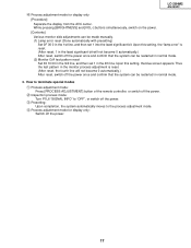
... special modes 1 Process adjustment mode: Press [PROCESS ADJUSTMENT] button of the remote controller, or switch off the power. 2 Inspection process mode: Turn P1L6 "SIGNAL INFO" to "OFF", or switch off the power. 3 Presetting: Upon completion, the system automatically moves to the process adjustment mode. 4 Process adjustment mode for display only [Procedure] Separate the display from the AVC center. Upon this setting, the blue screen appears. Upon this setting, the "lamp error" is reset. (After reset, the...
... special modes 1 Process adjustment mode: Press [PROCESS ADJUSTMENT] button of the remote controller, or switch off the power. 2 Inspection process mode: Turn P1L6 "SIGNAL INFO" to "OFF", or switch off the power. 3 Presetting: Upon completion, the system automatically moves to the process adjustment mode. 4 Process adjustment mode for display only [Procedure] Separate the display from the AVC center. Upon this setting, the blue screen appears. Upon this setting, the "lamp error" is reset. (After reset, the...

Service Manual
Page 19
...reset in Sharp Corporation control area only Monitor side EEPROM reset Start updating the center side program Start updating the monitor side program G/A test pattern G/A masking I2C device control I2C device control I2C device control I2C device control Resetting center side accumulated operation time Resetting monitor side accumulated operation time Speaker mute control Auto-wide speed setting UPD64082YNR intensity setting 130 Component 15k/50Hz black level setting 81 Component 15k/50Hz contrast setting 57 Component 15k/50Hz red gain setting 73 Component 15k/50Hz blue gain setting...
...reset in Sharp Corporation control area only Monitor side EEPROM reset Start updating the center side program Start updating the monitor side program G/A test pattern G/A masking I2C device control I2C device control I2C device control I2C device control Resetting center side accumulated operation time Resetting monitor side accumulated operation time Speaker mute control Auto-wide speed setting UPD64082YNR intensity setting 130 Component 15k/50Hz black level setting 81 Component 15k/50Hz contrast setting 57 Component 15k/50Hz red gain setting 73 Component 15k/50Hz blue gain setting...

Service Manual
Page 26
... I2C DATA NOISE LEVEL Resetting the times of lamp errors counted Writing in the I2C data set separately (For test) Measuring the noise level of MIN, MEDIUM and MAX by pressing the adjustment button (such as VOL +/-) Displaying the single color solid signal in the following sequence by pressing the adjustment button Red → Green → Blue → White → Black Switching the brightness to BRIGHT...
... I2C DATA NOISE LEVEL Resetting the times of lamp errors counted Writing in the I2C data set separately (For test) Measuring the noise level of MIN, MEDIUM and MAX by pressing the adjustment button (such as VOL +/-) Displaying the single color solid signal in the following sequence by pressing the adjustment button Red → Green → Blue → White → Black Switching the brightness to BRIGHT...
Service Manual
Page 27
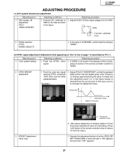
... the color bar signal carrying NTSC composite 100% white and 0% white (pedestal black). (Example) 1. Operate the adjustment button in the figure below) is not found in the figure. If "N358" is deviated from the value.) 1. If there is no change against lowering the value, it is described as shown in the last part of the 1st line, press [ 4 ] button of the remote controller...
... the color bar signal carrying NTSC composite 100% white and 0% white (pedestal black). (Example) 1. Operate the adjustment button in the figure below) is not found in the figure. If "N358" is deviated from the value.) 1. If there is no change against lowering the value, it is described as shown in the last part of the 1st line, press [ 4 ] button of the remote controller...
Service Manual
Page 37
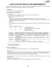
... reset by changing the value in the data write. LC-28HM2 AN-28SP2 HOW TO ADJUST DISPLAY UNIT INDEPENDENTLY The unit is factory adjusted to the AVC center unit) 2 Going into the process adjustment mode [Procedure] While pressing [BRIGHT] and [VOL DOWN] buttons simultaneously, switch on the main power. How to reset lamp error After parts replacement or repair, reset the lamp error (*1) in the following procedure. Preparation As power source, use...
... reset by changing the value in the data write. LC-28HM2 AN-28SP2 HOW TO ADJUST DISPLAY UNIT INDEPENDENTLY The unit is factory adjusted to the AVC center unit) 2 Going into the process adjustment mode [Procedure] While pressing [BRIGHT] and [VOL DOWN] buttons simultaneously, switch on the main power. How to reset lamp error After parts replacement or repair, reset the lamp error (*1) in the following procedure. Preparation As power source, use...
Service Manual
Page 42
LC-28HM2 AN-28SP2 No power supply TROUBLE SHOOTING TABLE (Continued) 42 Check LED lamp color. Green (Faulty condition) Press power button of IC2004. Check power supply at Yes pin (2) of P3601 on RC unit? Switch off the power. display process adjustment mode. Check power and GND of remote controller. Is pin (19) (MPOW) of both D501 and SC401? Check CCKM line peripherals of IC2004 at pin (5) of both display and center...
LC-28HM2 AN-28SP2 No power supply TROUBLE SHOOTING TABLE (Continued) 42 Check LED lamp color. Green (Faulty condition) Press power button of IC2004. Check power supply at Yes pin (2) of P3601 on RC unit? Switch off the power. display process adjustment mode. Check power and GND of remote controller. Is pin (19) (MPOW) of both D501 and SC401? Check CCKM line peripherals of IC2004 at pin (5) of both display and center...
Service Manual
Page 44
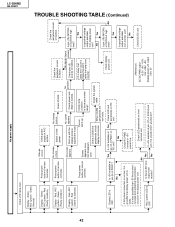
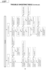
... the low level? Check rear terminal unit. Are there normal audio No outputs from pins (1) and (7) of IC306? terminal unit. No Monitor output in main menu is set video 3 to "variable". Yes Is pin (9) of IC301. No Check the peripherals of IC301 at pins (1) and (7) of IC305? Does output icon show headphone when volume key is operated? peripherals of IC401. Check...
... the low level? Check rear terminal unit. Are there normal audio No outputs from pins (1) and (7) of IC306? terminal unit. No Monitor output in main menu is set video 3 to "variable". Yes Is pin (9) of IC301. No Check the peripherals of IC301 at pins (1) and (7) of IC305? Does output icon show headphone when volume key is operated? peripherals of IC401. Check...

Service Manual
Page 46
... No color production of video line signals (Commonly supplied between IC401 and IC801.) No color production of component line signals Yes Is 3.58MHz supplied to SC503, but no color production. outputs at pins (3) and (6) of IC801? Is there normal output at pins (4), (7) and (9) of IC7001? Yes Check if "Monochrome" setting is in the case of the rear terminal unit. The term "video S" denotes video 1 (S video input) and video 2 (S video input) signals...
... No color production of video line signals (Commonly supplied between IC401 and IC801.) No color production of component line signals Yes Is 3.58MHz supplied to SC503, but no color production. outputs at pins (3) and (6) of IC801? Is there normal output at pins (4), (7) and (9) of IC7001? Yes Check if "Monochrome" setting is in the case of the rear terminal unit. The term "video S" denotes video 1 (S video input) and video 2 (S video input) signals...

Service Manual
Page 51
... digital RGB signals and supplied to PC board after detecting the picture motion. It performs various controls. » IC1101-1121, IC1124 Gradation power block. The detection of user setting, it controls the headphone output volume, treble, bass, balance and loudness. Ë AVC System » IC401 (CXA2069Q) 7-input and 3-output selector IC. The video signals received in normal operation) » IC2004 (IX3421CE) Monitor side microcomputer. Another function is used in...
... digital RGB signals and supplied to PC board after detecting the picture motion. It performs various controls. » IC1101-1121, IC1124 Gradation power block. The detection of user setting, it controls the headphone output volume, treble, bass, balance and loudness. Ë AVC System » IC401 (CXA2069Q) 7-input and 3-output selector IC. The video signals received in normal operation) » IC2004 (IX3421CE) Monitor side microcomputer. Another function is used in...

Service Manual
Page 52
... IC. When horizontal frequency is either 31kHz (480p) or 33kHz (1080i), the external clamp pulse needs to be digitized by AD converter, given size and positional adjustments, synthesized in accordance with user setting suited for vertical position adjustment. » IC3901 (CXA2020M) Ground waves multiple sound IC. The video signals thus received at PC board will be supplied to the monitor. * Component signal Y+ component video signal supplied from the ground wave...
... IC. When horizontal frequency is either 31kHz (480p) or 33kHz (1080i), the external clamp pulse needs to be digitized by AD converter, given size and positional adjustments, synthesized in accordance with user setting suited for vertical position adjustment. » IC3901 (CXA2020M) Ground waves multiple sound IC. The video signals thus received at PC board will be supplied to the monitor. * Component signal Y+ component video signal supplied from the ground wave...

Service Manual
Page 60
... driver 110 For VESA spec mount Panel link decoder circuit Audio LR drive circuit LINK LINK DCDC REM AMP SP LR Lamp disconnection protector circuit LAMPG LG LG LG_5 LG_6 BOSE speaker Panel link cable AMP power unit LG_7 LG_8 BOSE BOSE LR 180 20 LG_9 LG_10 LG_11 LG_12 To BOSE speaker (AMP side) Lamp GND PWB Connector cable REM Remote control receiver/LED PWB AC power cable...
... driver 110 For VESA spec mount Panel link decoder circuit Audio LR drive circuit LINK LINK DCDC REM AMP SP LR Lamp disconnection protector circuit LAMPG LG LG LG_5 LG_6 BOSE speaker Panel link cable AMP power unit LG_7 LG_8 BOSE BOSE LR 180 20 LG_9 LG_10 LG_11 LG_12 To BOSE speaker (AMP side) Lamp GND PWB Connector cable REM Remote control receiver/LED PWB AC power cable...


