
Operation Manual
Page 6
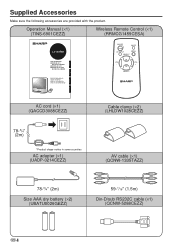
...-1/16" (1.5m) Din-D/sub RS232C cable (×1) (QCNW-5288CEZZ) US 4 Operation Manual (×1) (TINS-6901CEZZ) Wireless Remote Control (×1) (RRMCG1459CESA) LC-20VM2 LCD AV MONITOR MONITEUR AV À CRISTAUX LIQUIDES MONITOR AV LCD MONITOR AV DE TELA DE CRISTAL LÍQUIDO OPERATION MANUAL MODE D'EMPLOI MANUAL DE MANEJO MANUAL DE OPERAÇÃO ESPAÑ...
...-1/16" (1.5m) Din-D/sub RS232C cable (×1) (QCNW-5288CEZZ) US 4 Operation Manual (×1) (TINS-6901CEZZ) Wireless Remote Control (×1) (RRMCG1459CESA) LC-20VM2 LCD AV MONITOR MONITEUR AV À CRISTAUX LIQUIDES MONITOR AV LCD MONITOR AV DE TELA DE CRISTAL LÍQUIDO OPERATION MANUAL MODE D'EMPLOI MANUAL DE MANEJO MANUAL DE OPERAÇÃO ESPAÑ...
Operation Manual
Page 7
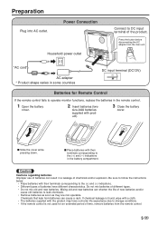
... a shorter life expectancy due to storage conditions. • If the remote control is not used for Remote Control If the remote control fails to operate monitor functions, replace the batteries in some countries DC input terminal (DC13V) POWER INPUT DC13V Batteries for an extended period of new batteries and/or cause...
... a shorter life expectancy due to storage conditions. • If the remote control is not used for Remote Control If the remote control fails to operate monitor functions, replace the batteries in some countries DC input terminal (DC13V) POWER INPUT DC13V Batteries for an extended period of new batteries and/or cause...

Operation Manual
Page 12
... indicator Switching AV INPUT AV1/AV2/COMPONENT/RGB ON/OFF MUTE AV INPUT MENU SELECT VOL - Note 1. x RGB: Personal computer connected to turn on the monitor. To change the AV input mode, press AV INPUT while the AV input mode is connected with cables, the S-video input terminal takes precedence. S-video...
... indicator Switching AV INPUT AV1/AV2/COMPONENT/RGB ON/OFF MUTE AV INPUT MENU SELECT VOL - Note 1. x RGB: Personal computer connected to turn on the monitor. To change the AV input mode, press AV INPUT while the AV input mode is connected with cables, the S-video input terminal takes precedence. S-video...

Operation Manual
Page 13
... Operation VOLUME 5‰ VOLUME 1‰ VOLUME ‰ VOLUME 3‰ Power ON/OFF standby ON/OFF MUTE s To turn off the monitor, press Power ON/OFF. The Power indicator will turn the monitor back on, press Power ON/OFF again. To mute sound s Press MUTE to the previous level. s To turn red. The...
... Operation VOLUME 5‰ VOLUME 1‰ VOLUME ‰ VOLUME 3‰ Power ON/OFF standby ON/OFF MUTE s To turn off the monitor, press Power ON/OFF. The Power indicator will turn the monitor back on, press Power ON/OFF again. To mute sound s Press MUTE to the previous level. s To turn red. The...

Operation Manual
Page 17
... can be set by using SELECT and VOL (+)/ (-) buttons. ABC ABC RIGHT/LEFT [NORMAL] Normal horizontal [MIRROR] Mirror image → To display mirror images for monitoring. 5 After changing PRESET items, press MENU to the initial screen. 15 US If no button is pressed during the 30 seconds, the display returns to...
... can be set by using SELECT and VOL (+)/ (-) buttons. ABC ABC RIGHT/LEFT [NORMAL] Normal horizontal [MIRROR] Mirror image → To display mirror images for monitoring. 5 After changing PRESET items, press MENU to the initial screen. 15 US If no button is pressed during the 30 seconds, the display returns to...

Operation Manual
Page 19
... the RGB Connection Cable s Align the pins of this unit and those of the RGB connection cable used to computer This LCD AV monitor can be used as the monitor of computer and display mode. Connecting to connect the computer and insert, then securely fasten with the following type of personal computer.
... the RGB Connection Cable s Align the pins of this unit and those of the RGB connection cable used to computer This LCD AV monitor can be used as the monitor of computer and display mode. Connecting to connect the computer and insert, then securely fasten with the following type of personal computer.
Operation Manual
Page 21
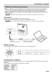
...Pin No. 1 2 34 5 67 89 6 3 Signal - Note This operation system should be used by a person who is set, the LCD Monitor can be made, enabling automatic programed playing. RS - - 5 4 2 1 Communication conditions Set the RS232C communications settings on the computer to using the ...section (see page 6). SG - Connecting to computer RS232C terminal specifications s When a program is accustomed to match the LCD Monitor's communications conditions. Note Mount the cable clamps when connecting cables to the supplied Din-D/sub RS232C for the connections. CONTROL Din-D/...
...Pin No. 1 2 34 5 67 89 6 3 Signal - Note This operation system should be used by a person who is set, the LCD Monitor can be made, enabling automatic programed playing. RS - - 5 4 2 1 Communication conditions Set the RS232C communications settings on the computer to using the ...section (see page 6). SG - Connecting to computer RS232C terminal specifications s When a program is accustomed to match the LCD Monitor's communications conditions. Note Mount the cable clamps when connecting cables to the supplied Din-D/sub RS232C for the connections. CONTROL Din-D/...

Operation Manual
Page 22
...command without displaying the On-screen Display. The LCD Monitor operates according to the received command and sends a ... _ _ _ 2 I C E D _ _ _ 1 I R G B _ _ _ 1 I C H K _ _ _ 0 M E S Y _ _ _ 1 M E S Y _ _ _ 2 M E S Y _ _ _ 3 M E S Y _ _ _ 4 M E S Y _ _ _ 5 M E S Y _ _ _ 6 US 20 Connecting to computer Communication procedure Send the control commands from the LCD Monitor is being sent, send each adjustment menu and checking the status with the On-screen Display. Commands Example: The AV input mode set to...
...command without displaying the On-screen Display. The LCD Monitor operates according to the received command and sends a ... _ _ _ 2 I C E D _ _ _ 1 I R G B _ _ _ 1 I C H K _ _ _ 0 M E S Y _ _ _ 1 M E S Y _ _ _ 2 M E S Y _ _ _ 3 M E S Y _ _ _ 4 M E S Y _ _ _ 5 M E S Y _ _ _ 6 US 20 Connecting to computer Communication procedure Send the control commands from the LCD Monitor is being sent, send each adjustment menu and checking the status with the On-screen Display. Commands Example: The AV input mode set to...
Operation Manual
Page 24
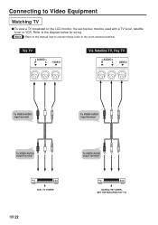
Via TV AUDIO R L VIDEO Via Satellite TV, Pay TV AUDIO R L VIDEO To VIDEO/AUDIO input terminal To VIDEO/AUDIO input terminal To VIDEO/AUDIO output terminal To VIDEO/AUDIO output terminal VCR, TV TUNER US 22 SATELLITE TUNER, SET TOP BOX(FOR PAY TV) Note Refer to the manual how to connect these tuner to the diagram below for wiring. Refer to the room antenna terminal. Connecting to Video Equipment Watching TV s To view a TV broadcast on the LCD monitor, the set-top box must be used with a TV tuner, satellite tuner or VCR.
Via TV AUDIO R L VIDEO Via Satellite TV, Pay TV AUDIO R L VIDEO To VIDEO/AUDIO input terminal To VIDEO/AUDIO input terminal To VIDEO/AUDIO output terminal To VIDEO/AUDIO output terminal VCR, TV TUNER US 22 SATELLITE TUNER, SET TOP BOX(FOR PAY TV) Note Refer to the manual how to connect these tuner to the diagram below for wiring. Refer to the room antenna terminal. Connecting to Video Equipment Watching TV s To view a TV broadcast on the LCD monitor, the set-top box must be used with a TV tuner, satellite tuner or VCR.

Operation Manual
Page 26
Digital Video Disc COMPONENT(INPUT) VIDEO AUDIO Y PB(CB) PR(CR) R L To VIDEO input terminal of COMPONENT To AUDIO input terminal of COMPONENT To VIDEO output terminal of COMPONENT To AUDIO output terminal of video equipment as follows. Connecting to Video Equipment Connecting with VIDEO Equipment s This LCD AV monitor can be connected with the most of COMPONENT US 24 DVD TUNER/BAND AUX 1 AUX 2 AUX 3 SURROUND ON/OFF DVD PLAYER
Digital Video Disc COMPONENT(INPUT) VIDEO AUDIO Y PB(CB) PR(CR) R L To VIDEO input terminal of COMPONENT To AUDIO input terminal of COMPONENT To VIDEO output terminal of COMPONENT To AUDIO output terminal of video equipment as follows. Connecting to Video Equipment Connecting with VIDEO Equipment s This LCD AV monitor can be connected with the most of COMPONENT US 24 DVD TUNER/BAND AUX 1 AUX 2 AUX 3 SURROUND ON/OFF DVD PLAYER
Operation Manual
Page 28
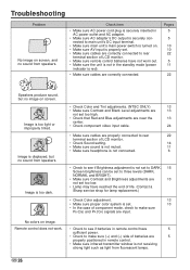
...• Make sure Contrast and Brightness adjustments are 13 not set too low. • Lamp may have reached the end of life. (Contact a Sharp service shop for lamp replacement.) • Check Color adjustment. 13 • Make sure proper color system is set. 13 • In the case ...the 13 center. • Check component video input cable. 24 • Make sure cables are properly connected to rear 22 terminal section of LCD monitor. • Make sure remote control batteries have 5 sufficient power. • Check to see if batteries in the standby mode (power indicator is...
...• Make sure Contrast and Brightness adjustments are 13 not set too low. • Lamp may have reached the end of life. (Contact a Sharp service shop for lamp replacement.) • Check Color adjustment. 13 • Make sure proper color system is set. 13 • In the case ...the 13 center. • Check component video input cable. 24 • Make sure cables are properly connected to rear 22 terminal section of LCD monitor. • Make sure remote control batteries have 5 sufficient power. • Check to see if batteries in the standby mode (power indicator is...


