DT-500 Operation Manual
Page 2
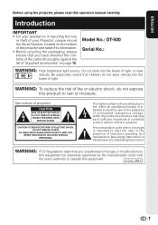
...OF ELECTRIC SHOCK, DO NOT REMOVE COVER. ONLY 1 Model No.: DT-500 Serial No.: WARNING: High brightness light source. U.S.A. WARNING: To reduce the risk of "Supplied accessories" on the bottom of the projector and retain this information. • Before recycling the packaging, please ...ensure that may be of sufficient magnitude to constitute a risk or electric shock to operate this operation manual carefully. The lightning flash with arrowhead symbol...
...OF ELECTRIC SHOCK, DO NOT REMOVE COVER. ONLY 1 Model No.: DT-500 Serial No.: WARNING: High brightness light source. U.S.A. WARNING: To reduce the risk of "Supplied accessories" on the bottom of the projector and retain this information. • Before recycling the packaging, please ...ensure that may be of sufficient magnitude to constitute a risk or electric shock to operate this operation manual carefully. The lightning flash with arrowhead symbol...
DT-500 Operation Manual
Page 3
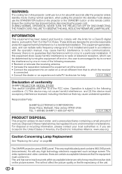
.../TV technician for help. As with the limits for about 90 seconds after the projector enters standby mode. FAILURE TO OBSERVE THIS WILL RESULT IN PREMATURE LAMP FAILURE. Disposal of conformity SHARP PROJECTOR, MODEL DT-500 This device complies with the operation manual, may be determined by turning the equipment off and on, the user is...
.../TV technician for help. As with the limits for about 90 seconds after the projector enters standby mode. FAILURE TO OBSERVE THIS WILL RESULT IN PREMATURE LAMP FAILURE. Disposal of conformity SHARP PROJECTOR, MODEL DT-500 This device complies with the operation manual, may be determined by turning the equipment off and on, the user is...
DT-500 Operation Manual
Page 4
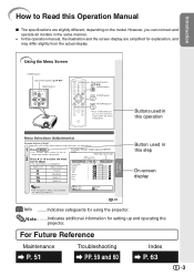
...Selected input mode Menu icons Picture Picture Mode Contrast Bright Color Tint Sharp Red Blue INPUT 1 Standard 0 0 0 0 0 0 0 Note • The "Fine Sync" menu is not available for setting up and operating the projector. Note .........Indicates additional information for INPUT 3 or INPUT 4. For... simplified for explanation, and may differ slightly from the actual display. Buttons used in this operation manual, the illustration and the screen display are slightly different, depending on the projector. 1 Press dMENU. • The "Picture" menu screen for the selected input mode is ...
...Selected input mode Menu icons Picture Picture Mode Contrast Bright Color Tint Sharp Red Blue INPUT 1 Standard 0 0 0 0 0 0 0 Note • The "Fine Sync" menu is not available for setting up and operating the projector. Note .........Indicates additional information for INPUT 3 or INPUT 4. For... simplified for explanation, and may differ slightly from the actual display. Buttons used in this operation manual, the illustration and the screen display are slightly different, depending on the projector. 1 Press dMENU. • The "Picture" menu screen for the selected input mode is ...
DT-500 Operation Manual
Page 5
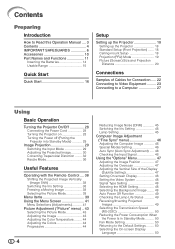
...Preparing Introduction How to Read this Operation Manual .... 3 Contents 4 IMPORTANT SAFEGUARDS 6 Accessories 10 Part Names and Functions 11 Inserting the Batteries 14 Usable Range 15 Quick Start Quick Start 16 Setup Setting up the Projector 18 Setting up the Projector 18 Standard Setup (Front Projection) .......... ......... 23 Connecting to a Computer 27 Using Basic Operation Turning the Projector On/Off 28 Connecting the Power Cord 28 Turning the Projector on 28 Turning the Power off (Putting the Projector into Standby Mode 29 Image Projection 29 Switching the Input Mode 29 ...
...Preparing Introduction How to Read this Operation Manual .... 3 Contents 4 IMPORTANT SAFEGUARDS 6 Accessories 10 Part Names and Functions 11 Inserting the Batteries 14 Usable Range 15 Quick Start Quick Start 16 Setup Setting up the Projector 18 Setting up the Projector 18 Standard Setup (Front Projection) .......... ......... 23 Connecting to a Computer 27 Using Basic Operation Turning the Projector On/Off 28 Connecting the Power Cord 28 Turning the Projector on 28 Turning the Power off (Putting the Projector into Standby Mode 29 Image Projection 29 Switching the Input Mode 29 ...
DT-500 Operation Manual
Page 10
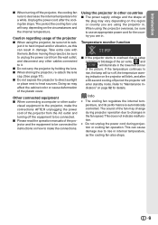
...cord from the AC outlet and turning off the projector, the cooling fan runs to decrease the internal temperature for details. Doing so may vary depending on the circumstances and the internal temperature. I Please read the operation manuals of the fan may change during projection or cooling... fan operation. ing indicator on the projector will blink, and after the cooling fan stops. The sound of the projector and the equipment to be connected for instructions on page...
...cord from the AC outlet and turning off the projector, the cooling fan runs to decrease the internal temperature for details. Doing so may vary depending on the circumstances and the internal temperature. I Please read the operation manuals of the fan may change during projection or cooling... fan operation. ing indicator on the projector will blink, and after the cooling fan stops. The sound of the projector and the equipment to be connected for instructions on page...
DT-500 Operation Manual
Page 12
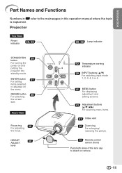
... the picture. 15 Remote control sensor (front) Push both sides of the lens cap to the main pages in Z refer to attach or remove. 11 Projector Top View Power indicator 28, 52 28, 52 Lamp indicator STANDBY/ON 28 button For turning the power on the menu. Introduction Part Names and... Functions Numbers in this operation manual where the topic is explained. ENTER button 41 For setting items selected or adjusted on and putting the projector into standby mode.
... the picture. 15 Remote control sensor (front) Push both sides of the lens cap to the main pages in Z refer to attach or remove. 11 Projector Top View Power indicator 28, 52 28, 52 Lamp indicator STANDBY/ON 28 button For turning the power on the menu. Introduction Part Names and... Functions Numbers in this operation manual where the topic is explained. ENTER button 41 For setting items selected or adjusted on and putting the projector into standby mode.
DT-500 Operation Manual
Page 14
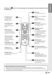
... images. 29 INPUT 1, 2, 3, 4, 5 and 6 buttons For switching to the respective input signal type. Using the Kensington Lock on the projector • This projector has a Kensington Security Standard connector for use with the system for instructions on how to use it to the main pages in this operation... manual where the topic is explained. 28 ON button For turning the power on the remote control. 38 IRIS button For switching...
... images. 29 INPUT 1, 2, 3, 4, 5 and 6 buttons For switching to the respective input signal type. Using the Kensington Lock on the projector • This projector has a Kensington Security Standard connector for use with the system for instructions on how to use it to the main pages in this operation... manual where the topic is explained. 28 ON button For turning the power on the remote control. 38 IRIS button For switching...

DT-500 Operation Manual
Page 23
... available) Video INPUT4 Camera/ video game Cables for a camera or a video game Compo- Equipment Input Signal Cable Terminal on the projector Audio-visual equipment HDMI video HDMI cable (commercially available) INPUT6 Component video Component cable (commercially available) Component video 3 RCA to 15...camera or a video game INPUT3 S-video Cables for Connection • For more details of connection and cables, refer to the operation manual of the connecting equipment. • You may need other cables or connectors not listed below. Samples of Cables for a camera or...
... available) Video INPUT4 Camera/ video game Cables for a camera or a video game Compo- Equipment Input Signal Cable Terminal on the projector Audio-visual equipment HDMI video HDMI cable (commercially available) INPUT6 Component video Component cable (commercially available) Component video 3 RCA to 15...camera or a video game INPUT3 S-video Cables for Connection • For more details of connection and cables, refer to the operation manual of the connecting equipment. • You may need other cables or connectors not listed below. Samples of Cables for a camera or...
DT-500 Operation Manual
Page 47
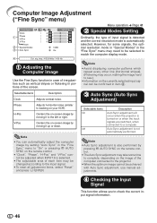
...select "Reset" and press i ENTER. 3 Auto Sync (Auto Sync Adjustment) Selectable items On Off Description Auto Sync adjustment will occur when the projector is also performed by setting "Auto Sync" in item 4. V-Pos Centers the on-screen image by moving it to tracking on the image of ...the computer connected to the projector. • When the optimum image cannot be achieved with Auto Sync adjustment, use manual adjustments. 4 Checking the Input Signal This function allows you to check the current input signal information...
...select "Reset" and press i ENTER. 3 Auto Sync (Auto Sync Adjustment) Selectable items On Off Description Auto Sync adjustment will occur when the projector is also performed by setting "Auto Sync" in item 4. V-Pos Centers the on-screen image by moving it to tracking on the image of ...the computer connected to the projector. • When the optimum image cannot be achieved with Auto Sync adjustment, use manual adjustments. 4 Checking the Input Signal This function allows you to check the current input signal information...
DT-500 Operation Manual
Page 60
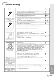
... the computer's operation manual for it is green on • See "Maintenance Indicators". 52 the projector illuminates or blinks in red. INPUT 6 (Component). 48 Picture is suddenly heated, condensation may form on INPUT 5 (RGB)/INPUT 6 (RGB). Appendix 59 If the projector is blurred; This ...set when connecting notebook computer. • The lamp unit cover is not installed correctly. • Cables incorrectly connected to the projector. • "Bright" is due to the external output. Picture is to switch its signal output settings. occasionally heard from the...
... the computer's operation manual for it is green on • See "Maintenance Indicators". 52 the projector illuminates or blinks in red. INPUT 6 (Component). 48 Picture is suddenly heated, condensation may form on INPUT 5 (RGB)/INPUT 6 (RGB). Appendix 59 If the projector is blurred; This ...set when connecting notebook computer. • The lamp unit cover is not installed correctly. • Cables incorrectly connected to the projector. • "Bright" is due to the external output. Picture is to switch its signal output settings. occasionally heard from the...
DT-500 Operation Manual
Page 62
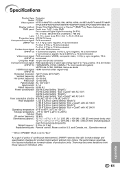
and Canada, etc., Operation manual *1 When STANDBY Mode is set to "...°C to make design and specification changes for U.S. The performance specification figures indicated are nominal values of continuous improvement, SHARP reserves the right to +60°C) Cabinet Plastic I/R carrier frequency 38 kHz Dimensions (approx.) 12 13/32" &#...terminated (INPUT 5) HORIZONTAL SYNC. SIGNAL: TTL level (positive/negative) VERTICAL SYNC. Specifications Product type Projector Model DT-500 Video system NTSC3.58/NTSC4.43/PAL/PAL-M/PAL-N/PAL-60/SECAM/DTV480I/DTV480P/ DTV540P/DTV576I/DTV576P/...
and Canada, etc., Operation manual *1 When STANDBY Mode is set to "...°C to make design and specification changes for U.S. The performance specification figures indicated are nominal values of continuous improvement, SHARP reserves the right to +60°C) Cabinet Plastic I/R carrier frequency 38 kHz Dimensions (approx.) 12 13/32" &#...terminated (INPUT 5) HORIZONTAL SYNC. SIGNAL: TTL level (positive/negative) VERTICAL SYNC. Specifications Product type Projector Model DT-500 Video system NTSC3.58/NTSC4.43/PAL/PAL-M/PAL-N/PAL-60/SECAM/DTV480I/DTV480P/ DTV540P/DTV576I/DTV576P/...


