
Technical Guide
Page 1
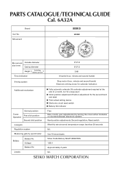
Use 10-second gate. No. Movement SEIKO 6A32A Movement Outside diameter size (mm) Casing diameter Height ( Including battery portion ) Time indication Ø 27.8 Ø 27.3 3.69 3 hands (hour, minute and second hands) ..., Second regulation, Reset switch Monthly rate at normal temperature range: less than 20 seconds Nil. Silver Oxide Battery SB-AP (SR927SW) 1.55 V Approximately 4 years Nil. PARTS CATALOGUE /TECHNICAL GUIDE Cal. 6A32A Brand Cal.
Use 10-second gate. No. Movement SEIKO 6A32A Movement Outside diameter size (mm) Casing diameter Height ( Including battery portion ) Time indication Ø 27.8 Ø 27.3 3.69 3 hands (hour, minute and second hands) ..., Second regulation, Reset switch Monthly rate at normal temperature range: less than 20 seconds Nil. Silver Oxide Battery SB-AP (SR927SW) 1.55 V Approximately 4 years Nil. PARTS CATALOGUE /TECHNICAL GUIDE Cal. 6A32A Brand Cal.
Technical Guide
Page 2
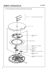
PARTS CATALOGUE ● Order of disassembly for the hands, dial and wheels on the back side Cal. 6A32A 1 HOUR, MINUTE AND SECOND HANDS 2 DIAL 3 DATE DIAL GUARD 0808 051 4 DATE DIAL 5 INTERMEDIATE 24-HOUR WHEEL 0817 046 6 24-HOUR WHEEL 1019 001 7 HOUR WHEEL 0273 031 (for models of the medium hand installation height) 8 DATE DRIVING WHEEL 0802 035 9 INTERMEDIATE DATE DRIVING WHEEL C 0817 045 2
PARTS CATALOGUE ● Order of disassembly for the hands, dial and wheels on the back side Cal. 6A32A 1 HOUR, MINUTE AND SECOND HANDS 2 DIAL 3 DATE DIAL GUARD 0808 051 4 DATE DIAL 5 INTERMEDIATE 24-HOUR WHEEL 0817 046 6 24-HOUR WHEEL 1019 001 7 HOUR WHEEL 0273 031 (for models of the medium hand installation height) 8 DATE DRIVING WHEEL 0802 035 9 INTERMEDIATE DATE DRIVING WHEEL C 0817 045 2
Technical Guide
Page 3
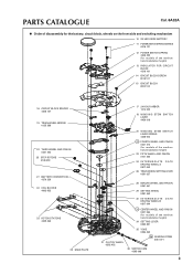
PARTS CATALOGUE Cal. 6A32A ● Order of disassembly for the battery, circuit block, wheels on the front side and switching mechanism 10 SILVER OXIDE BATTERY 11 ...
PARTS CATALOGUE Cal. 6A32A ● Order of disassembly for the battery, circuit block, wheels on the front side and switching mechanism 10 SILVER OXIDE BATTERY 11 ...
Technical Guide
Page 4
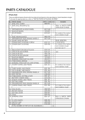
... AND PINION 0231 454 0701 450 0817 043 4146 453 0391 027 4270 239 0261 451 0281 452 0817 044 0221 064 1 1 1 2 1 1 1 1 1 1 For models of parts which are determined based on the case design or hand installation height. To choose the appropriate one, refer to WATCH... CD-ROM. 37 CLUTCH WHEEL 38 SWITCH CAM 39 MAIN PLATE 0282 452 1 4295 006 1 0100 293 1 TOTAL NUMBER OF PARTS (TO BE ASSEMBLED) 44 4 No. PARTS CATALOGUE Cal. 6A32A [Parts list] There are different types of the medium hand installation height 32 COIL BLOCK 33 ROTOR STATOR 34 SETTING LEVER 35 YOKE...
... AND PINION 0231 454 0701 450 0817 043 4146 453 0391 027 4270 239 0261 451 0281 452 0817 044 0221 064 1 1 1 2 1 1 1 1 1 1 For models of parts which are determined based on the case design or hand installation height. To choose the appropriate one, refer to WATCH... CD-ROM. 37 CLUTCH WHEEL 38 SWITCH CAM 39 MAIN PLATE 0282 452 1 4295 006 1 0100 293 1 TOTAL NUMBER OF PARTS (TO BE ASSEMBLED) 44 4 No. PARTS CATALOGUE Cal. 6A32A [Parts list] There are different types of the medium hand installation height 32 COIL BLOCK 33 ROTOR STATOR 34 SETTING LEVER 35 YOKE...
Technical Guide
Page 7
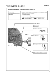
TECHNICAL GUIDE Cal. 6A32A Installation positions • Lubrication points • Remarks Reassembly (2) Lubricate the switching mechanism. ❇ Install the parts in the number order shown in the illustration below, paying attention to the following: mounting positions, direction of mounting, type of oil, lubrication point(s) and amount of lubrication. normal quantity liberal quantity 1 Clutch wheel 2 Switch cam 3 Winding stem (AO-3) 4 Yoke (AO-3) 5 Setting lever (AO-3) 6 Winding stem switching lever spring 7
TECHNICAL GUIDE Cal. 6A32A Installation positions • Lubrication points • Remarks Reassembly (2) Lubricate the switching mechanism. ❇ Install the parts in the number order shown in the illustration below, paying attention to the following: mounting positions, direction of mounting, type of oil, lubrication point(s) and amount of lubrication. normal quantity liberal quantity 1 Clutch wheel 2 Switch cam 3 Winding stem (AO-3) 4 Yoke (AO-3) 5 Setting lever (AO-3) 6 Winding stem switching lever spring 7
Technical Guide
Page 8
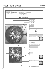
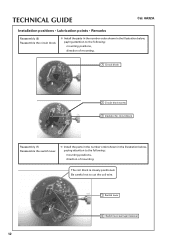
... wheel and pinion 8 TECHNICAL GUIDE Cal. 6A32A Installation positions • Lubrication points • Remarks Reassembly (3) Reassemble the wheels and train wheel bridge. ❇ Install the parts in the number order shown in the illustration below, paying attention to the following: mounting positions, direction of mounting, type of oil, lubrication point(s) and...
... wheel and pinion 8 TECHNICAL GUIDE Cal. 6A32A Installation positions • Lubrication points • Remarks Reassembly (3) Reassemble the wheels and train wheel bridge. ❇ Install the parts in the number order shown in the illustration below, paying attention to the following: mounting positions, direction of mounting, type of oil, lubrication point(s) and...
Technical Guide
Page 9
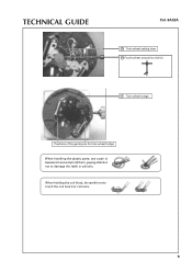
TECHNICAL GUIDE Cal. 6A32A 15 Train wheel setting lever 16 Fourth wheel and pinion (AO-3) 17 Train wheel bridge Positions of the guide pins for train wheel bridge When handling the plastic parts, use a pair of tweezers to securely hold them, paying attention not to touch the coil board or coil wire. 9 When holding the coil block, be careful not to damage the teeth or pinions.
TECHNICAL GUIDE Cal. 6A32A 15 Train wheel setting lever 16 Fourth wheel and pinion (AO-3) 17 Train wheel bridge Positions of the guide pins for train wheel bridge When handling the plastic parts, use a pair of tweezers to securely hold them, paying attention not to touch the coil board or coil wire. 9 When holding the coil block, be careful not to damage the teeth or pinions.
Technical Guide
Page 11
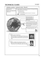
... TECHNICAL GUIDE Cal. 6A32A Installation positions • Lubrication points • Remarks Reassembly (5) Reassemble the circuit block spacer and winding stem switch lever. ❇ Install the parts in the number order shown in the illustration on installation of the winding stem switch lever Make sure that the winding stem switch lever does...
... TECHNICAL GUIDE Cal. 6A32A Installation positions • Lubrication points • Remarks Reassembly (5) Reassemble the circuit block spacer and winding stem switch lever. ❇ Install the parts in the number order shown in the illustration on installation of the winding stem switch lever Make sure that the winding stem switch lever does...
Technical Guide
Page 12
...TECHNICAL GUIDE Cal. 6A32A Installation positions • Lubrication points • Remarks Reassembly (6) Reassemble the circuit block. ❇ Install the parts in the number order shown in the illustration below , paying attention to the following : mounting positions, direction of mounting. Be careful.... 1 Circuit block 2 Circuit block screw 3 Insulator for circuit block Reassembly (7) Reassemble the switch lever. ❇ Install the parts in the number order shown in the illustration below , paying attention to cut the coil wire. 1 Switch lever 2 Switch lever springs (4...
...TECHNICAL GUIDE Cal. 6A32A Installation positions • Lubrication points • Remarks Reassembly (6) Reassemble the circuit block. ❇ Install the parts in the number order shown in the illustration below , paying attention to the following : mounting positions, direction of mounting. Be careful.... 1 Circuit block 2 Circuit block screw 3 Insulator for circuit block Reassembly (7) Reassemble the switch lever. ❇ Install the parts in the number order shown in the illustration below , paying attention to cut the coil wire. 1 Switch lever 2 Switch lever springs (4...
Technical Guide
Page 13
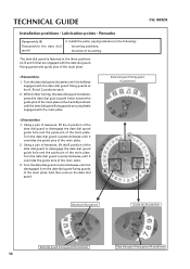
... the wheels on the back side Cal. 6A32A 1 Intermediate date driving wheel C 2 Date driving wheel Pinion of tweezers to securely hold the plastic parts, paying attention so as shown in the correct direction. Ensure that the flattened side is set in the illustration. • When mounting the plastic... parts, carefully check that the 24-hour wheel is positioned properly as not to the Note 1 below. 5 Intermediate 24-hour wheel 6 Date dial Note...
... the wheels on the back side Cal. 6A32A 1 Intermediate date driving wheel C 2 Date driving wheel Pinion of tweezers to securely hold the plastic parts, paying attention so as shown in the correct direction. Ensure that the flattened side is set in the illustration. • When mounting the plastic... parts, carefully check that the 24-hour wheel is positioned properly as not to the Note 1 below. 5 Intermediate 24-hour wheel 6 Date dial Note...
Technical Guide
Page 14
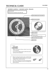
TECHNICAL GUIDE Cal. 6A32A Installation positions • Lubrication points • Remarks Reassembly (9) Reassemble the date dial guard. ❇ Install the parts, paying attention to the following: mounting positions, direction of the main plate at the A, B and C positions each. 2. While further turning the date dial guard clockwise, ...
TECHNICAL GUIDE Cal. 6A32A Installation positions • Lubrication points • Remarks Reassembly (9) Reassemble the date dial guard. ❇ Install the parts, paying attention to the following: mounting positions, direction of the main plate at the A, B and C positions each. 2. While further turning the date dial guard clockwise, ...
Technical Guide
Page 15
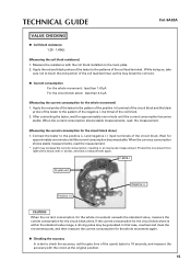
..., set the gate time of the quartz tester to touch the end portion of the circuit block. In that case, overhaul and clean the movement parts, and then measure the current consumption for approximately one minute until the current consumption becomes stable.
..., set the gate time of the quartz tester to touch the end portion of the circuit block. In that case, overhaul and clean the movement parts, and then measure the current consumption for approximately one minute until the current consumption becomes stable.
Technical Guide
Page 16
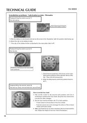
... 2. Attach the clip to damage the arbors of the battery holder is no friction between the hour hand and the dial. Reassembling the exterior parts (3) Set the hour hand, minute hand and second hand. Make sure that there is attached to set it off. How to the main ...dial properly and firmly press it clockwise to set the hour hand 1. TECHNICAL GUIDE Installation positions • Lubrication points • Remarks Reassembling the exterior parts (1) Set the battery. Slide the battery in the direction shown by the arrow in the illustration (with the positive side facing up.) 2. Place...
... 2. Attach the clip to damage the arbors of the battery holder is no friction between the hour hand and the dial. Reassembling the exterior parts (3) Set the hour hand, minute hand and second hand. Make sure that there is attached to set it off. How to the main ...dial properly and firmly press it clockwise to set the hour hand 1. TECHNICAL GUIDE Installation positions • Lubrication points • Remarks Reassembling the exterior parts (1) Set the battery. Slide the battery in the direction shown by the arrow in the illustration (with the positive side facing up.) 2. Place...


