
Technical Guide
Page 1
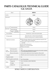
PARTS CATALOGUE /TECHNICAL GUIDE Cal. 6A32A Brand Cal. Use 10-second gate. No. Silver Oxide Battery SB-AP (SR927SW) 1.55 V Approximately 4 years Nil. Movement SEIKO 6A32A Movement Outside diameter size (mm) Casing diameter Height ( Including battery portion ) Time indication Ø 27.8 Ø 27.3 3.69 3 hands (hour, minute and second hands) ...
PARTS CATALOGUE /TECHNICAL GUIDE Cal. 6A32A Brand Cal. Use 10-second gate. No. Silver Oxide Battery SB-AP (SR927SW) 1.55 V Approximately 4 years Nil. Movement SEIKO 6A32A Movement Outside diameter size (mm) Casing diameter Height ( Including battery portion ) Time indication Ø 27.8 Ø 27.3 3.69 3 hands (hour, minute and second hands) ...
Technical Guide
Page 5
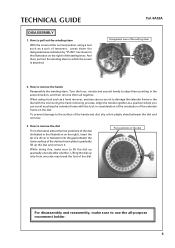
... on the right) of the setting lever. When using a tool such as a pair of the dial and main plate to which the crown is attached. TECHNICAL GUIDE DISASSEMBLY 1. How to align them all -purpose movement holder. 5 Turn the hour, minute and second hands to remove the hands Reassemble the winding stem. How...
... on the right) of the setting lever. When using a tool such as a pair of the dial and main plate to which the crown is attached. TECHNICAL GUIDE DISASSEMBLY 1. How to align them all -purpose movement holder. 5 Turn the hour, minute and second hands to remove the hands Reassemble the winding stem. How...
Technical Guide
Page 6
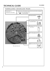
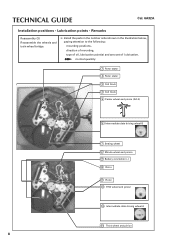
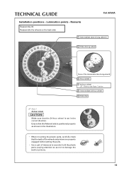
TECHNICAL GUIDE Cal. 6A32A Installation positions • Lubrication points • Remarks Reassembly (1) Lubricate the main plate. ❇ Make sure to lubricate the exact lubrication points with an adequate amount of the correct type of the rotor (AO-2) 6 normal quantity 1 Center pipe (AO-3) 2 Lower guide hole of the minute wheel and pinion (AO-3) 3 Guide pin of the train wheel setting lever (AO-3) Main plate (back side) 4 Pin of the setting lever (AO-3) 5 Pin of the setting wheel (AO-3) 6 & 7 Lower holes of oil.
TECHNICAL GUIDE Cal. 6A32A Installation positions • Lubrication points • Remarks Reassembly (1) Lubricate the main plate. ❇ Make sure to lubricate the exact lubrication points with an adequate amount of the correct type of the rotor (AO-2) 6 normal quantity 1 Center pipe (AO-3) 2 Lower guide hole of the minute wheel and pinion (AO-3) 3 Guide pin of the train wheel setting lever (AO-3) Main plate (back side) 4 Pin of the setting lever (AO-3) 5 Pin of the setting wheel (AO-3) 6 & 7 Lower holes of oil.
Technical Guide
Page 7
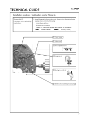
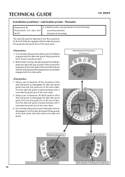
TECHNICAL GUIDE Cal. 6A32A Installation positions • Lubrication points • Remarks Reassembly (2) Lubricate the switching mechanism. ❇ Install the parts in the number order shown in the illustration below, paying attention to the following: mounting positions, direction of mounting, type of oil, lubrication point(s) and amount of lubrication. normal quantity liberal quantity 1 Clutch wheel 2 Switch cam 3 Winding stem (AO-3) 4 Yoke (AO-3) 5 Setting lever (AO-3) 6 Winding stem switching lever spring 7
TECHNICAL GUIDE Cal. 6A32A Installation positions • Lubrication points • Remarks Reassembly (2) Lubricate the switching mechanism. ❇ Install the parts in the number order shown in the illustration below, paying attention to the following: mounting positions, direction of mounting, type of oil, lubrication point(s) and amount of lubrication. normal quantity liberal quantity 1 Clutch wheel 2 Switch cam 3 Winding stem (AO-3) 4 Yoke (AO-3) 5 Setting lever (AO-3) 6 Winding stem switching lever spring 7
Technical Guide
Page 8
TECHNICAL GUIDE Cal. 6A32A Installation positions • Lubrication points • Remarks Reassembly (3) Reassemble the wheels and train wheel bridge. ❇ Install the parts in the number order ...
TECHNICAL GUIDE Cal. 6A32A Installation positions • Lubrication points • Remarks Reassembly (3) Reassemble the wheels and train wheel bridge. ❇ Install the parts in the number order ...
Technical Guide
Page 9
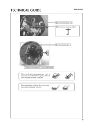
TECHNICAL GUIDE Cal. 6A32A 15 Train wheel setting lever 16 Fourth wheel and pinion (AO-3) 17 Train wheel bridge Positions of the guide pins for train wheel bridge When handling the plastic parts, use a pair of tweezers to securely hold them, paying attention not to touch the coil board or coil wire. 9 When holding the coil block, be careful not to damage the teeth or pinions.
TECHNICAL GUIDE Cal. 6A32A 15 Train wheel setting lever 16 Fourth wheel and pinion (AO-3) 17 Train wheel bridge Positions of the guide pins for train wheel bridge When handling the plastic parts, use a pair of tweezers to securely hold them, paying attention not to touch the coil board or coil wire. 9 When holding the coil block, be careful not to damage the teeth or pinions.

Technical Guide
Page 10
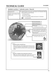
TECHNICAL GUIDE Cal. 6A32A Installation positions • Lubrication points • Remarks Reassembly (4) Lubricate the train wheel bridge. ❇ Make sure to lubricate the exact lubrication points with an adequate amount of the correct type of the rotor (AO-2) 10 normal quantity 1 Minute wheel and pinion (AO-3) 2 Pin for crown switch (AO-3) 3 Upper pivot of the rotor (AO-2) 4 Upper pivot of oil.
TECHNICAL GUIDE Cal. 6A32A Installation positions • Lubrication points • Remarks Reassembly (4) Lubricate the train wheel bridge. ❇ Make sure to lubricate the exact lubrication points with an adequate amount of the correct type of the rotor (AO-2) 10 normal quantity 1 Minute wheel and pinion (AO-3) 2 Pin for crown switch (AO-3) 3 Upper pivot of the rotor (AO-2) 4 Upper pivot of oil.
Technical Guide
Page 11
... Place the 24-H arbor in the position where it does not cover the holes indicated in the illustration below, paying attention to the Note 2 below . TECHNICAL GUIDE Cal. 6A32A Installation positions • Lubrication points • Remarks Reassembly (5) Reassemble the circuit block spacer and winding stem switch lever. ❇ Install the parts in...
... Place the 24-H arbor in the position where it does not cover the holes indicated in the illustration below, paying attention to the Note 2 below . TECHNICAL GUIDE Cal. 6A32A Installation positions • Lubrication points • Remarks Reassembly (5) Reassemble the circuit block spacer and winding stem switch lever. ❇ Install the parts in...
Technical Guide
Page 12
Be careful not to the following: mounting positions, direction of mounting. TECHNICAL GUIDE Cal. 6A32A Installation positions • Lubrication points • Remarks Reassembly (6) Reassemble the circuit block. ❇ Install the parts in the number order shown in the ...
Be careful not to the following: mounting positions, direction of mounting. TECHNICAL GUIDE Cal. 6A32A Installation positions • Lubrication points • Remarks Reassembly (6) Reassemble the circuit block. ❇ Install the parts in the number order shown in the ...
Technical Guide
Page 13
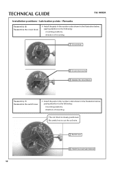
Ensure that the flattened side is positioned properly as not to damage the teeth or pinions. 13 TECHNICAL GUIDE Installation positions • Lubrication points • Remarks Reassembly (8) Reassemble the wheels on the back side Cal. 6A32A 1 Intermediate date driving wheel C 2 Date driving wheel Pinion ...
Ensure that the flattened side is positioned properly as not to damage the teeth or pinions. 13 TECHNICAL GUIDE Installation positions • Lubrication points • Remarks Reassembly (8) Reassemble the wheels on the back side Cal. 6A32A 1 Intermediate date driving wheel C 2 Date driving wheel Pinion ...
Technical Guide
Page 14
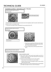
... main plate. 1. Turn the date dial guard counterclockwise until it is halfway engaged with the main plate. C A Guide pin (B position) Guide pin (A position) Date dial guard fixing guard (B positions) 14 Date dial guard fixing guard (A positions) TECHNICAL GUIDE Cal. 6A32A Installation positions • Lubrication points • Remarks Reassembly (9) Reassemble the date dial guard. ❇...
... main plate. 1. Turn the date dial guard counterclockwise until it is halfway engaged with the main plate. C A Guide pin (B position) Guide pin (A position) Date dial guard fixing guard (B positions) 14 Date dial guard fixing guard (A positions) TECHNICAL GUIDE Cal. 6A32A Installation positions • Lubrication points • Remarks Reassembly (9) Reassemble the date dial guard. ❇...
Technical Guide
Page 15
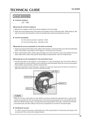
... pulse may increase the current consumption, resulting in an inaccurate measurement. When the current consumption shows stable measurements, read the measurement. * Light may be generated. TECHNICAL GUIDE Cal. 6A32A VALUE CHECKING ● Coil block resistance 1.28 - 1.48kW [Measuring the coil block resistance] 1. While doing so, take a measurement again. Connect the tester to...
... pulse may increase the current consumption, resulting in an inaccurate measurement. When the current consumption shows stable measurements, read the measurement. * Light may be generated. TECHNICAL GUIDE Cal. 6A32A VALUE CHECKING ● Coil block resistance 1.28 - 1.48kW [Measuring the coil block resistance] 1. While doing so, take a measurement again. Connect the tester to...
Technical Guide
Page 16
... the calendar frame of the hour hand if necessary. 16 Positions of the battery holder is no friction between the hour hand and the dial. TECHNICAL GUIDE Installation positions • Lubrication points • Remarks Reassembling the exterior parts (1) Set the battery. Adjust the height of the dial. Check the two positions of...
... the calendar frame of the hour hand if necessary. 16 Positions of the battery holder is no friction between the hour hand and the dial. TECHNICAL GUIDE Installation positions • Lubrication points • Remarks Reassembling the exterior parts (1) Set the battery. Adjust the height of the dial. Check the two positions of...
Technical Guide
Page 17
... so as to position the tip at a time out of the target time of the date change , remove the minute hand and mount it again. 3. TECHNICAL GUIDE Cal. 6A32A How to the 12 o'clock position. 2. Hand installation check ups 1.
... so as to position the tip at a time out of the target time of the date change , remove the minute hand and mount it again. 3. TECHNICAL GUIDE Cal. 6A32A How to the 12 o'clock position. 2. Hand installation check ups 1.
Technical Guide
Page 18
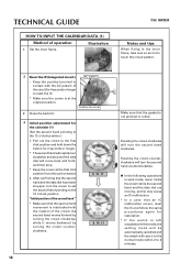
... as this may cause an IC malfunction. * In a case that the second hand and the date dial have been stopped, turn the second hand clockwise. TECHNICAL GUIDE HOW TO INPUT THE CALENDAR DATA (1) Method of the circuit for 4 seconds or longer to reset the IC. * Make sure the crown is not pinched...
... as this may cause an IC malfunction. * In a case that the second hand and the date dial have been stopped, turn the second hand clockwise. TECHNICAL GUIDE HOW TO INPUT THE CALENDAR DATA (1) Method of the circuit for 4 seconds or longer to reset the IC. * Make sure the crown is not pinched...
Technical Guide
Page 19
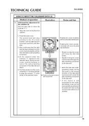
... movement of operation 5 Initial position adjustment for the calendar (2) (Set the date dial to show the numeral "1".) * Keep the crown at the first click position. TECHNICAL GUIDE Cal. 6A32A HOW TO INPUT THE CALENDAR DATA (2) Method of the date dial. * If the watch is left unoperated in this mode, the setting mode...
... movement of operation 5 Initial position adjustment for the calendar (2) (Set the date dial to show the numeral "1".) * Keep the crown at the first click position. TECHNICAL GUIDE Cal. 6A32A HOW TO INPUT THE CALENDAR DATA (2) Method of the date dial. * If the watch is left unoperated in this mode, the setting mode...
Technical Guide
Page 20
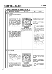
... crown clockwise will turn the crown counterclockwise to cancel the self-propelling movement of the date indictor and stop pointing to the 10 o'clock position. TECHNICAL GUIDE Cal. 6A32A HOW TO INPUT THE CALENDAR DATA (3) Method of the calendar frame.
... crown clockwise will turn the crown counterclockwise to cancel the self-propelling movement of the date indictor and stop pointing to the 10 o'clock position. TECHNICAL GUIDE Cal. 6A32A HOW TO INPUT THE CALENDAR DATA (3) Method of the calendar frame.
Technical Guide
Page 21
... of operation 3. At the moment when the month numeral you wish to set. * The second hand remains pointing to the 11 o'clock position. 4 5 6 When it . TECHNICAL GUIDE HOW TO INPUT THE CALENDAR DATA (4) Method of the year;
... of operation 3. At the moment when the month numeral you wish to set. * The second hand remains pointing to the 11 o'clock position. 4 5 6 When it . TECHNICAL GUIDE HOW TO INPUT THE CALENDAR DATA (4) Method of the year;
Technical Guide
Page 22
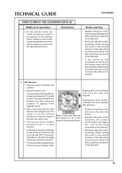
TECHNICAL GUIDE HOW TO INPUT THE CALENDAR DATA (5) Method of operation Illustration 9 Push the crown back into the original position. Cal. 6A32A Notes and tips * If the watch is left unoperated in this mode, the setting mode will be automatically cancelled and the watch will return to the normal mode within 2 to 3 minutes. • The hour, minute and second hands will start moving. • The date dial will start moving and stop when the current date numeral appears in the calendar frame. 22
TECHNICAL GUIDE HOW TO INPUT THE CALENDAR DATA (5) Method of operation Illustration 9 Push the crown back into the original position. Cal. 6A32A Notes and tips * If the watch is left unoperated in this mode, the setting mode will be automatically cancelled and the watch will return to the normal mode within 2 to 3 minutes. • The hour, minute and second hands will start moving. • The date dial will start moving and stop when the current date numeral appears in the calendar frame. 22

Technical Guide
Page 23
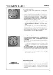
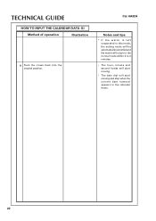
... will move forward and stop showing the date numeral at the initial position in the calendar frame. * Keep the crown at the first click position. 1. TECHNICAL GUIDE HOW TO CHECK THE CALENDAR SETTINGS (1) Method of operation 1 How to check the initial setting position of the date numeral * Keep the crown at the...
... will move forward and stop showing the date numeral at the initial position in the calendar frame. * Keep the crown at the first click position. 1. TECHNICAL GUIDE HOW TO CHECK THE CALENDAR SETTINGS (1) Method of operation 1 How to check the initial setting position of the date numeral * Keep the crown at the...
