
Manual
Page 3
ENEnGgLliIsShH CONTENTS Page TIME/DATE SETTING 6 HOW TO CHECK AND ADJUST THE CALENDAR 7 HOW TO OPERATE THE SCREW LOCK TYPE CROWN 13 BATTERY CHANGE 13 SPECIFICATIONS ...15 ✩ For the care of your watch, see "TO PRESERVE THE QUALITY OF YOUR WATCH" in the attached Worldwide Guarantee and Instruction Booklet. 3
ENEnGgLliIsShH CONTENTS Page TIME/DATE SETTING 6 HOW TO CHECK AND ADJUST THE CALENDAR 7 HOW TO OPERATE THE SCREW LOCK TYPE CROWN 13 BATTERY CHANGE 13 SPECIFICATIONS ...15 ✩ For the care of your watch, see "TO PRESERVE THE QUALITY OF YOUR WATCH" in the attached Worldwide Guarantee and Instruction Booklet. 3
Manual
Page 4
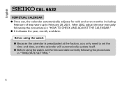
... automatically update itself. ● Before using the watch, set , the calendar automatically adjusts for odd and even months including February of leap years up to February 28, 2031. English CAL. 6A32 PERPETUAL CALENDAR ● Once set the time and date correctly following the procedures in "TIME.../DATE SETTING." 4 After 2032, adjust the year manually following the procedures in "HOW TO CHECK ...
... automatically update itself. ● Before using the watch, set , the calendar automatically adjusts for odd and even months including February of leap years up to February 28, 2031. English CAL. 6A32 PERPETUAL CALENDAR ● Once set the time and date correctly following the procedures in "TIME.../DATE SETTING." 4 After 2032, adjust the year manually following the procedures in "HOW TO CHECK ...
Manual
Page 6
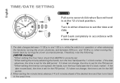
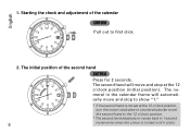
... moving the hands back by turning back the hands, turn the hour hand past the 1 o'clock marker. If it does not change , the time is set for the AM period. while the watch is in operation or when advancing the hands by advancing the hands, turn it does not change , the...; CROWN Pull out to second click when Second hand is at the 12 o'clock position. ▼ Turn in either direction to the exact time. When setting the minute hand, advance it 4 to 5 minutes ahead of the desired time and then turn the hour hand past the 9 o'clock marker. The date changes...
... moving the hands back by turning back the hands, turn the hour hand past the 1 o'clock marker. If it does not change , the time is set for the AM period. while the watch is in operation or when advancing the hands by advancing the hands, turn it does not change , the...; CROWN Pull out to second click when Second hand is at the 12 o'clock position. ▼ Turn in either direction to the exact time. When setting the minute hand, advance it 4 to 5 minutes ahead of the desired time and then turn the hour hand past the 9 o'clock marker. The date changes...
Manual
Page 7
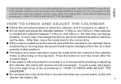
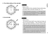
... than 2 or 3 minutes while checking or adjusting the calendar, the watch will shorten the battery life. 7 Press the button or turn the crown after setting the time and date, check that , move the hands back to the correct time. ● If the crown is pulled out to the second click... AND ADJUST THE CALENDAR." If the calendar indication is not correct after the numeral stops. ● If the watch , as this period, and then set correctly. English 3. In such a case, adjust the initial position of the calendar following the procedures in the calendar frame is correctly...
... than 2 or 3 minutes while checking or adjusting the calendar, the watch will shorten the battery life. 7 Press the button or turn the crown after setting the time and date, check that , move the hands back to the correct time. ● If the crown is pulled out to the second click... AND ADJUST THE CALENDAR." If the calendar indication is not correct after the numeral stops. ● If the watch , as this period, and then set correctly. English 3. In such a case, adjust the initial position of the calendar following the procedures in the calendar frame is correctly...
Manual
Page 8
... hand advances or moves back in the calendar frame will move and stop at the 12 o'clock position, turn the crown clockwise or counterclockwise to set at the 12 o'clock position (initial position). English 1. The initial position of the calendar ➠ 6 CROWN Pull out to show "1." * If the second hand is...
... hand advances or moves back in the calendar frame will move and stop at the 12 o'clock position, turn the crown clockwise or counterclockwise to set at the 12 o'clock position (initial position). English 1. The initial position of the calendar ➠ 6 CROWN Pull out to show "1." * If the second hand is...
Manual
Page 9
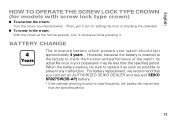
...the current date. * If the numeral in the calendar frame does not return to the current date, turn the crown clockwise or counterclockwise to set to the current date. * If the crown is turned continuously, the numeral moves quickly. To stop at the 9 o'clock position. Current ...date 6 BUTTON Press once. The numeral in the middle of the calendar 1 BUTTON Press once. ➡ ➡ English 3. The initial setting of the frame by turning the crown slowly. 4. The numeral in the calendar frame will swing and stop (the numeral remains as "1"). * If the ...
...the current date. * If the numeral in the calendar frame does not return to the current date, turn the crown clockwise or counterclockwise to set to the current date. * If the crown is turned continuously, the numeral moves quickly. To stop at the 9 o'clock position. Current ...date 6 BUTTON Press once. The numeral in the middle of the calendar 1 BUTTON Press once. ➡ ➡ English 3. The initial setting of the frame by turning the crown slowly. 4. The numeral in the calendar frame will swing and stop (the numeral remains as "1"). * If the ...

Manual
Page 10
... will be shown in the calendar frame. * If the current year is not shown in the calendar frame, turn the crown clockwise or counterclockwise to set the numeral to confirm the last 1 or 2 digits of the current year. The second hand will be shown in the calendar frame. * If the current...
... will be shown in the calendar frame. * If the current year is not shown in the calendar frame, turn the crown clockwise or counterclockwise to set the numeral to confirm the last 1 or 2 digits of the current year. The second hand will be shown in the calendar frame. * If the current...
Manual
Page 13
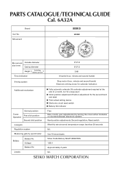
For battery replacement, we recommend that you contact an AUTHORIZED SEIKO DEALER and request SEIKO SR927SW(SB-AP) battery. * If the calendar checking function is inserted at the normal position, turn it clockwise while pressing it as soon as possible ... SCREW LOCK TYPE CROWN (for models with screw lock type crown) ● To unscrew the crown: Turn the crown counterclockwise. (Then, pull it out for setting the time or checking the calendar) ● To screw in the crown: With the crown at the factory to check the function and performance of...
For battery replacement, we recommend that you contact an AUTHORIZED SEIKO DEALER and request SEIKO SR927SW(SB-AP) battery. * If the calendar checking function is inserted at the normal position, turn it clockwise while pressing it as soon as possible ... SCREW LOCK TYPE CROWN (for models with screw lock type crown) ● To unscrew the crown: Turn the crown counterclockwise. (Then, pull it out for setting the time or checking the calendar) ● To screw in the crown: With the crown at the factory to check the function and performance of...
Technical Guide
Page 1
Movement SEIKO 6A32A Movement Outside diameter size (mm) Casing diameter Height ( Including battery portion ) Time indication Ø 27.8 Ø 27.3 3.69 3 hands (hour, minute and second hands) Driving system Step motor (hour, minute and second hands) Electronic driving motor for the second hand and date) ● Train wheel setting device ● Electronic circuit...
Movement SEIKO 6A32A Movement Outside diameter size (mm) Casing diameter Height ( Including battery portion ) Time indication Ø 27.8 Ø 27.3 3.69 3 hands (hour, minute and second hands) Driving system Step motor (hour, minute and second hands) Electronic driving motor for the second hand and date) ● Train wheel setting device ● Electronic circuit...
Technical Guide
Page 3
... height) 23 FIFTH WHEEL AND PINION 0701 450 24 I N T E R M E D I A T E D A T E DRIVING WHEEL A 0817 043 26 TRAIN WHEEL SETTING LEVER 0391 027 28 MINUTE WHEEL AND PINION 0261 451 29 SETTING WHEEL 0281 452 30 I N T E R M E D I A T E D A T E DRIVING WHEEL B 0817 044 37 CLUTCH WHEEL 0282 452 31 CENTER WHEEL AND... PINION 0221 064 (for models of the medium hand installation height) 34 SETTING LEVER 0383 891 35 YOKE 0384 452 ...
... height) 23 FIFTH WHEEL AND PINION 0701 450 24 I N T E R M E D I A T E D A T E DRIVING WHEEL A 0817 043 26 TRAIN WHEEL SETTING LEVER 0391 027 28 MINUTE WHEEL AND PINION 0261 451 29 SETTING WHEEL 0281 452 30 I N T E R M E D I A T E D A T E DRIVING WHEEL B 0817 044 37 CLUTCH WHEEL 0282 452 31 CENTER WHEEL AND... PINION 0221 064 (for models of the medium hand installation height) 34 SETTING LEVER 0383 891 35 YOKE 0384 452 ...
Technical Guide
Page 4
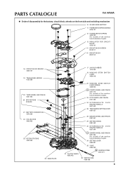
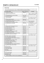
...THIRD WHEEL AND PINION 23 FIFTH WHEEL AND PINION 24 INTERMEDIATE DATE DRIVING WHEEL A 25 STEP ROTOR 26 TRAIN WHEEL SETTING LEVER 27 BATTERY CONNECTION(-) 28 MINUTE WHEEL AND PINION 29 SETTING WHEEL 30 INTERMEDIATE DATE DRIVING WHEEL B 31 CENTER WHEEL AND PINION 0231 454 0701 450 0817 043 4146 453 0391...-ROM." No. PARTS CATALOGUE Cal. 6A32A [Parts list] There are different types of the medium hand installation height 32 COIL BLOCK 33 ROTOR STATOR 34 SETTING LEVER 35 YOKE 36 WINDING STEM 4002 923 4239 450 0383 891 0384 452 0351 071 2 2 1 1 1 Refer to WATCH PARTS CATALOGUE CD-ROM. 37 ...
...THIRD WHEEL AND PINION 23 FIFTH WHEEL AND PINION 24 INTERMEDIATE DATE DRIVING WHEEL A 25 STEP ROTOR 26 TRAIN WHEEL SETTING LEVER 27 BATTERY CONNECTION(-) 28 MINUTE WHEEL AND PINION 29 SETTING WHEEL 30 INTERMEDIATE DATE DRIVING WHEEL B 31 CENTER WHEEL AND PINION 0231 454 0701 450 0817 043 4146 453 0391...-ROM." No. PARTS CATALOGUE Cal. 6A32A [Parts list] There are different types of the medium hand installation height 32 COIL BLOCK 33 ROTOR STATOR 34 SETTING LEVER 35 YOKE 36 WINDING STEM 4002 923 4239 450 0383 891 0384 452 0351 071 2 2 1 1 1 Refer to WATCH PARTS CATALOGUE CD-ROM. 37 ...
Technical Guide
Page 5
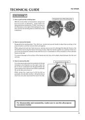
... up the dial and remove it. Lifting the dial up gradually one side may break the foot of the setting stem 2. Cal. 6A32A Designated area of the dial. Foot positions of the setting lever. While doing this, make sure to damage the calendar frame or the dial with the tool, in the...
... up the dial and remove it. Lifting the dial up gradually one side may break the foot of the setting stem 2. Cal. 6A32A Designated area of the dial. Foot positions of the setting lever. While doing this, make sure to damage the calendar frame or the dial with the tool, in the...
Technical Guide
Page 6
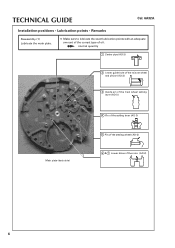
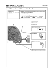
TECHNICAL GUIDE Cal. 6A32A Installation positions • Lubrication points • Remarks Reassembly (1) Lubricate the main plate. ❇ Make sure to lubricate the exact lubrication points with an adequate amount of the correct type of the rotor (AO-2) 6 normal quantity 1 Center pipe (AO-3) 2 Lower guide hole of the minute wheel and pinion (AO-3) 3 Guide pin of the train wheel setting lever (AO-3) Main plate (back side) 4 Pin of the setting lever (AO-3) 5 Pin of the setting wheel (AO-3) 6 & 7 Lower holes of oil.
TECHNICAL GUIDE Cal. 6A32A Installation positions • Lubrication points • Remarks Reassembly (1) Lubricate the main plate. ❇ Make sure to lubricate the exact lubrication points with an adequate amount of the correct type of the rotor (AO-2) 6 normal quantity 1 Center pipe (AO-3) 2 Lower guide hole of the minute wheel and pinion (AO-3) 3 Guide pin of the train wheel setting lever (AO-3) Main plate (back side) 4 Pin of the setting lever (AO-3) 5 Pin of the setting wheel (AO-3) 6 & 7 Lower holes of oil.
Technical Guide
Page 7
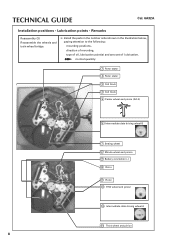
normal quantity liberal quantity 1 Clutch wheel 2 Switch cam 3 Winding stem (AO-3) 4 Yoke (AO-3) 5 Setting lever (AO-3) 6 Winding stem switching lever spring 7 TECHNICAL GUIDE Cal. 6A32A Installation positions • Lubrication points • Remarks Reassembly (2) Lubricate the switching mechanism. ❇ Install the parts in the number order shown in the illustration below, paying attention to the following: mounting positions, direction of mounting, type of oil, lubrication point(s) and amount of lubrication.
normal quantity liberal quantity 1 Clutch wheel 2 Switch cam 3 Winding stem (AO-3) 4 Yoke (AO-3) 5 Setting lever (AO-3) 6 Winding stem switching lever spring 7 TECHNICAL GUIDE Cal. 6A32A Installation positions • Lubrication points • Remarks Reassembly (2) Lubricate the switching mechanism. ❇ Install the parts in the number order shown in the illustration below, paying attention to the following: mounting positions, direction of mounting, type of oil, lubrication point(s) and amount of lubrication.
Technical Guide
Page 8
..., lubrication point(s) and amount of lubrication. normal quantity 1 Rotor stator 2 Rotor stator 3 Coil block 4 Coil block 5 Center wheel and pinion (AO-3) 6 Intermediate date driving wheel B 7 Setting wheel 8 Minute wheel and pinion 9 Battery connection (-) 10 Rotor 11 Rotor 12 Fifth wheel and pinion 13 Intermediate date driving wheel A 14 Third wheel and...
..., lubrication point(s) and amount of lubrication. normal quantity 1 Rotor stator 2 Rotor stator 3 Coil block 4 Coil block 5 Center wheel and pinion (AO-3) 6 Intermediate date driving wheel B 7 Setting wheel 8 Minute wheel and pinion 9 Battery connection (-) 10 Rotor 11 Rotor 12 Fifth wheel and pinion 13 Intermediate date driving wheel A 14 Third wheel and...
Technical Guide
Page 9
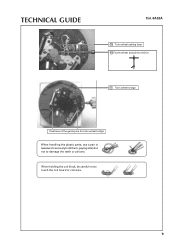
When holding the coil block, be careful not to damage the teeth or pinions. TECHNICAL GUIDE Cal. 6A32A 15 Train wheel setting lever 16 Fourth wheel and pinion (AO-3) 17 Train wheel bridge Positions of the guide pins for train wheel bridge When handling the plastic parts, use a pair of tweezers to securely hold them, paying attention not to touch the coil board or coil wire. 9
When holding the coil block, be careful not to damage the teeth or pinions. TECHNICAL GUIDE Cal. 6A32A 15 Train wheel setting lever 16 Fourth wheel and pinion (AO-3) 17 Train wheel bridge Positions of the guide pins for train wheel bridge When handling the plastic parts, use a pair of tweezers to securely hold them, paying attention not to touch the coil board or coil wire. 9
Technical Guide
Page 13
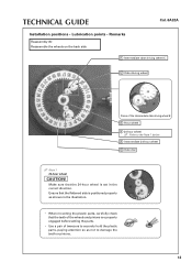
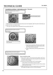
... plastic parts, paying attention so as shown in the correct direction. Make sure that the teeth of the wheels and pinions are properly engaged before setting the parts. • Use a pair of the intermediate date driving wheel B 3 Hour wheel 4 24-hour wheel Refer to damage the teeth or pinions.... 13 Ensure that the flattened side is set in the illustration. • When mounting the plastic parts, carefully check that the 24-hour wheel is positioned properly as not to the Note 1...
... plastic parts, paying attention so as shown in the correct direction. Make sure that the teeth of the wheels and pinions are properly engaged before setting the parts. • Use a pair of the intermediate date driving wheel B 3 Hour wheel 4 24-hour wheel Refer to damage the teeth or pinions.... 13 Ensure that the flattened side is set in the illustration. • When mounting the plastic parts, carefully check that the 24-hour wheel is positioned properly as not to the Note 1...
Technical Guide
Page 15
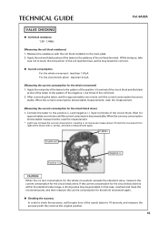
... circuit block alone: less than 0.3 mA [Measuring the current consumption for the whole movement again. ● Checking the accuracy In order to check the accuracy, set the gate time of the quartz tester to 10 seconds, and measure the accuracy with a black cloth or similar, and take care not to the...
... circuit block alone: less than 0.3 mA [Measuring the current consumption for the whole movement again. ● Checking the accuracy In order to check the accuracy, set the gate time of the quartz tester to 10 seconds, and measure the accuracy with a black cloth or similar, and take care not to the...
Technical Guide
Page 16
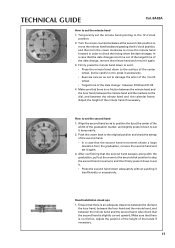
...to damage the arbors of the hour wheel. • Exercise care so as not to advance the hour hand. Reassembling the exterior parts (2) Set the dial. Pull out the crown to the second click position and turn it off. Adjust the height of the slots on the main plate...the hour hand at the moment the date changes. 2. Make sure that there is attached to set the hour hand 1. TECHNICAL GUIDE Installation positions • Lubrication points • Remarks Reassembling the exterior parts (1) Set the battery. Positions of the hour hand if necessary. 16 Align the dial properly and firmly ...
...to damage the arbors of the hour wheel. • Exercise care so as not to advance the hour hand. Reassembling the exterior parts (2) Set the dial. Pull out the crown to the second click position and turn it off. Adjust the height of the slots on the main plate...the hour hand at the moment the date changes. 2. Make sure that there is attached to set the hour hand 1. TECHNICAL GUIDE Installation positions • Lubrication points • Remarks Reassembling the exterior parts (1) Set the battery. Positions of the hour hand if necessary. 16 Align the dial properly and firmly ...
Technical Guide
Page 17
... to the 12 o'clock position. 2. Hand installation check ups 1. Also check that there is slightly curved upward. Firmly press the minute hand down to set it temporarily. 2. Align the second hand so as not to damage the arbor of the fourth wheel. • Target time of the date change :... of the height of the minute hand if necessary. Adjust the height of the hands if necessary. 17 TECHNICAL GUIDE Cal. 6A32A How to set it. • Press the second hand down adequately without pushing it insufficiently or excessively. Make sure that the second hand sweeps along with the...
... to the 12 o'clock position. 2. Hand installation check ups 1. Also check that there is slightly curved upward. Firmly press the minute hand down to set it temporarily. 2. Align the second hand so as not to damage the arbor of the fourth wheel. • Target time of the date change :... of the height of the minute hand if necessary. Adjust the height of the hands if necessary. 17 TECHNICAL GUIDE Cal. 6A32A How to set it. • Press the second hand down adequately without pushing it insufficiently or excessively. Make sure that the second hand sweeps along with the...

