Product Manual
Page 5
... 3 1.5 Seek time 3 1.6 Start and stop time 4 1.7 Power specifications 4 1.7.1 Voltage tolerances 4 1.7.2 Conducted noise 5 1.7.3 Power-management modes 5 1.8 Environment 7 1.8.1 Ambient temperature 7 1.8.2 Temperature gradient 7 1.8.3 Relative humidity 8 1.8.4 Altitude 8 1.8.5 Shock and vibration 8 1.9 Acoustics 8 1.10 Reliability 9 1.11 Auto-park 9 1.12 Agency listings 9 1.13 FCC verification 9 2.0 Configuration and mounting 11 2.1 Handling and static-discharge precautions 11 2.2 The ATA interface connector 12 2.3 Power connector 12 2.4 Master/slave jumper block 12...
... 3 1.5 Seek time 3 1.6 Start and stop time 4 1.7 Power specifications 4 1.7.1 Voltage tolerances 4 1.7.2 Conducted noise 5 1.7.3 Power-management modes 5 1.8 Environment 7 1.8.1 Ambient temperature 7 1.8.2 Temperature gradient 7 1.8.3 Relative humidity 8 1.8.4 Altitude 8 1.8.5 Shock and vibration 8 1.9 Acoustics 8 1.10 Reliability 9 1.11 Auto-park 9 1.12 Agency listings 9 1.13 FCC verification 9 2.0 Configuration and mounting 11 2.1 Handling and static-discharge precautions 11 2.2 The ATA interface connector 12 2.3 Power connector 12 2.4 Master/slave jumper block 12...
Product Manual
Page 6
iv Medalist XE Family Product Manual, Rev. B 2.4.4 Factory-test configuration 15 2.5 Optional drive activity LED 15 2.6 Mounting the drive 16 3.0 ATA interface 19 3.1 ATA interface connector pin assignments 19 3.2 Bus signal levels 19 3.3 Supported ATA commands 21 3.3.1 Identify Drive command (ECH 23 3.3.2 Set Features command (EFH 26 3.3.3 Set Multiple Mode command (C6H 28 3.3.4 Read Multiple command (C4H 28 3.3.5 Write Multiple command (C5H 29 3.4 Onboard drive diagnostics 30 3.5 ECC performance tests 30 3.6 Supported BIOS 31
iv Medalist XE Family Product Manual, Rev. B 2.4.4 Factory-test configuration 15 2.5 Optional drive activity LED 15 2.6 Mounting the drive 16 3.0 ATA interface 19 3.1 ATA interface connector pin assignments 19 3.2 Bus signal levels 19 3.3 Supported ATA commands 21 3.3.1 Identify Drive command (ECH 23 3.3.2 Set Features command (EFH 26 3.3.3 Set Multiple Mode command (C6H 28 3.3.4 Read Multiple command (C4H 28 3.3.5 Write Multiple command (C5H 29 3.4 Onboard drive diagnostics 30 3.5 ECC performance tests 30 3.6 Supported BIOS 31
Product Manual
Page 9
... bytes. Medalist XE Family Product Manual, Rev. SFF 8019: Identify Drive Data for Local Bus Attachments, Rev. 2.0; The Medalist drives are configured in translation mode at the factory. Note. The drives support LBA addressing and are referred to as the ST3660A. 1.1 Format configuration Seagate Medalist drives are met: • The number of sectors per track does not exceed 256. • The number of sectors per track and the number of sectors using the Identify Drive (ECH) command.) The...
... bytes. Medalist XE Family Product Manual, Rev. SFF 8019: Identify Drive Data for Local Bus Attachments, Rev. 2.0; The Medalist drives are configured in translation mode at the factory. Note. The drives support LBA addressing and are referred to as the ST3660A. 1.1 Format configuration Seagate Medalist drives are met: • The number of sectors per track does not exceed 256. • The number of sectors per track and the number of sectors using the Identify Drive (ECH) command.) The...
Product Manual
Page 10
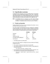
... the accessible hard disc capacity to determine the drive capacity. The overwrap condition for the ST3660A is: 1,057 - 1,024 = 33 cylinders for this limitation: • Use a BIOS that supports logical block addressing (LBA) or extended cylinder-head-sector (CHS) addressing. • Use a host adapter that supports more than 1,024 cylinders are used to 528 Mbytes. In an overwrap condition, only the overwrapping cylinders are specified in the translation geometry. 2 Medalist XE Family Product Manual...
... the accessible hard disc capacity to determine the drive capacity. The overwrap condition for the ST3660A is: 1,057 - 1,024 = 33 cylinders for this limitation: • Use a BIOS that supports logical block addressing (LBA) or extended cylinder-head-sector (CHS) addressing. • Use a host adapter that supports more than 1,024 cylinders are used to 528 Mbytes. In an overwrap condition, only the overwrapping cylinders are specified in the translation geometry. 2 Medalist XE Family Product Manual...
Product Manual
Page 13
... remains enabled, the heads are parked in the shipping zone and the spindle is needed . • Standby mode. The drive accepts all commands and returns to the Active mode whenever a seek, read or write operation is 10 Hz to zero, the drive enters the Idle mode. A hard reset or a soft reset returns the drive to speed. Medalist XE Family Product Manual, Rev. When the drive receives a Sleep Immediate command, it enters the Sleep mode. A soft reset preserves...
... remains enabled, the heads are parked in the shipping zone and the spindle is needed . • Standby mode. The drive accepts all commands and returns to the Active mode whenever a seek, read or write operation is 10 Hz to zero, the drive enters the Idle mode. A hard reset or a soft reset returns the drive to speed. Medalist XE Family Product Manual, Rev. When the drive receives a Sleep Immediate command, it enters the Sleep mode. A soft reset preserves...
Product Manual
Page 14
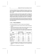
... Standby mode. See the Seagate ATA Interface Reference Manual, publication number 36111-xxx for details. There may be a slight delay between each time the drive completes a read, write or seek. the peak startup power is measured using the nominal voltages. • Seek current measurements are taken at the factory. Spinup power is enabled. These power dissipation values apply only when power management is averaged over 3 seconds. To enable power management, use the computer setup utility. 2. Use...
... Standby mode. See the Seagate ATA Interface Reference Manual, publication number 36111-xxx for details. There may be a slight delay between each time the drive completes a read, write or seek. the peak startup power is measured using the nominal voltages. • Seek current measurements are taken at the factory. Spinup power is enabled. These power dissipation values apply only when power management is averaged over 3 seconds. To enable power management, use the computer setup utility. 2. Use...
Product Manual
Page 17
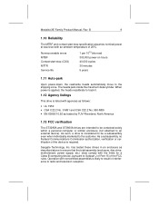
... the maximum data cylinder. Nonrecoverable errors MTBF Contact start -stop (CSS) MTTR Service life 1 per 1013 bits read 300,000 power-on hours 40,000 cycles 30 minutes 5 years 1.11 Auto-park Upon power-down, the read/write heads automatically move to ensure that the total assembly (enclosure, disc drive, motherboard, power supply, etc.) does comply with noncertified assemblies is listed with an ambient temperature of...
... the maximum data cylinder. Nonrecoverable errors MTBF Contact start -stop (CSS) MTTR Service life 1 per 1013 bits read 300,000 power-on hours 40,000 cycles 30 minutes 5 years 1.11 Auto-park Upon power-down, the read/write heads automatically move to ensure that the total assembly (enclosure, disc drive, motherboard, power supply, etc.) does comply with noncertified assemblies is listed with an ambient temperature of...
Product Manual
Page 19
... connector pins or the printed circuit board. Observe the following features: • The ATA interface connector • The power connector • The master/slave jumper block • The optional drive activity LED A brief discussion of the following standard handling and static-discharge precautions: Caution: • Keep the drive in its static-shielded bag until you void the warranty. Others are used to service the drive. Medalist XE Family Product Manual...
... connector pins or the printed circuit board. Observe the following features: • The ATA interface connector • The power connector • The master/slave jumper block • The optional drive activity LED A brief discussion of the following standard handling and static-discharge precautions: Caution: • Keep the drive in its static-shielded bag until you void the warranty. Others are used to service the drive. Medalist XE Family Product Manual...
Product Manual
Page 20
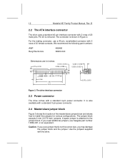
... 0.160 1.90 2.00 0.100 typ 0.070 ± 0.010 Figure 2. Pin 20 is not the correct size, you use a jumper that is removed. The drive interface connector 2.3 Power connector The drive comes with 2 rows of 20 male pins. 12 Medalist XE Family Product Manual, Rev. The connector is attached to install the jumpers for various configurations. We recommend the following part numbers: AMP Berg Electronics 499496 66900-040 Dimensions are in Figure 2.
... 0.160 1.90 2.00 0.100 typ 0.070 ± 0.010 Figure 2. Pin 20 is not the correct size, you use a jumper that is removed. The drive interface connector 2.3 Power connector The drive comes with 2 rows of 20 male pins. 12 Medalist XE Family Product Manual, Rev. The connector is attached to install the jumpers for various configurations. We recommend the following part numbers: AMP Berg Electronics 499496 66900-040 Dimensions are in Figure 2.
Product Manual
Page 21
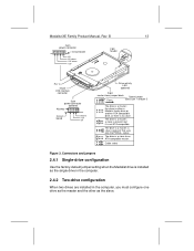
... return +12V Front 2-pin header - + Pin 1 40-pin ATA interface connector 3-pin power connector (optional) Keyway 123 Circuit board Ground +12V +5V Drive activity LED (optional) 8-pin master/slave jumper block Spare jumper 7 5 31 Front across pin 1 and pin 3 86 42 The drive is not ATA-compatible. The drive is a slave to an ATA-compatible master. The drive is a master; Connectors and jumpers 2.4.1 Single-drive configuration Use the factory-default jumper setting when the Medalist drive is a master; signal. The drive is installed as the single drive in the computer...
... return +12V Front 2-pin header - + Pin 1 40-pin ATA interface connector 3-pin power connector (optional) Keyway 123 Circuit board Ground +12V +5V Drive activity LED (optional) 8-pin master/slave jumper block Spare jumper 7 5 31 Front across pin 1 and pin 3 86 42 The drive is not ATA-compatible. The drive is a slave to an ATA-compatible master. The drive is a master; Connectors and jumpers 2.4.1 Single-drive configuration Use the factory-default jumper setting when the Medalist drive is a master; signal. The drive is installed as the single drive in the computer...
Product Manual
Page 22
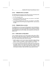
... interface cable built for slave identification. timing parameter of that cable connector.) Note that CSEL is : • An ATA-compatible drive • A non-ATA-compatible drive that is grounded at the host. 14 Medalist XE Family Product Manual, Rev. To configure your drives support cable select (CSEL), you need to install jumpers and to use a special cable-select cable as follows: • Install a jumper on pins 7 and 8. • You must use the cable select option to the ATA standard for cable-select. when the drive is ready 2.4.2.2 Medalist drive as master...
... interface cable built for slave identification. timing parameter of that cable connector.) Note that CSEL is : • An ATA-compatible drive • A non-ATA-compatible drive that is grounded at the host. 14 Medalist XE Family Product Manual, Rev. To configure your drives support cable select (CSEL), you need to install jumpers and to use a special cable-select cable as follows: • Install a jumper on pins 7 and 8. • You must use the cable select option to the ATA standard for cable-select. when the drive is ready 2.4.2.2 Medalist drive as master...
Product Manual
Page 23
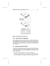
... inaccessible or inconvenient. There are available with or without the external activity LED shown in Figure 3 on pins 5 and 6 and pins 7 and 8 at computer Computer Figure 4. B 15 Slave CSEL not carried to test the drive at the factory. When jumpers are installed in both of this connector Master Pin 28 grounded at the same time. Connecting cable-selected drives 2.4.4 Factory-test configuration Do not install jumpers on page 13. Medalist XE Family Product Manual, Rev.
... inaccessible or inconvenient. There are available with or without the external activity LED shown in Figure 3 on pins 5 and 6 and pins 7 and 8 at computer Computer Figure 4. B 15 Slave CSEL not carried to test the drive at the factory. When jumpers are installed in both of this connector Master Pin 28 grounded at the same time. Connecting cable-selected drives 2.4.4 Factory-test configuration Do not install jumpers on page 13. Medalist XE Family Product Manual, Rev.
Product Manual
Page 27
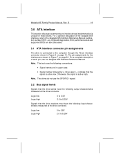
... commands and modes whose implementation is active high. For a complete description of the Seagate ATA interface, refer to the computer through the 40-pin interface connector shown in Figure 7 on page 13. Note. Logic low Logic high 0 to 0.8V 2.0 to 5.25V Signals that the signal is connected to the Seagate ATA Interface Reference Manual, publication number 36111-xxx. Onboard diagnostics, ECC performance test and supported BIOS are also discussed. 3.1 ATA interface connector pin...
... commands and modes whose implementation is active high. For a complete description of the Seagate ATA interface, refer to the computer through the 40-pin interface connector shown in Figure 7 on page 13. Note. Logic low Logic high 0 to 0.8V 2.0 to 5.25V Signals that the signal is connected to the Seagate ATA Interface Reference Manual, publication number 36111-xxx. Onboard diagnostics, ECC performance test and supported BIOS are also discussed. 3.1 ATA interface connector pin...
Product Manual
Page 29
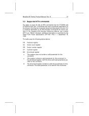
... ST3660A drives use , refer to the Seagate ATA Interface Reference Manual, part number 36111-xxx. Commands that have a particular application for this command. The table uses the following abbreviations: FR Features register SC Sector count register SN Sector number register CY Cylinder register DH Drive/head register n This register does not contain a valid parameter for this command. B 21 3.3 Supported ATA commands The table on page 22 lists all ATA commands that may be of all ATA interface commands...
... ST3660A drives use , refer to the Seagate ATA Interface Reference Manual, part number 36111-xxx. Commands that have a particular application for this command. The table uses the following abbreviations: FR Features register SC Sector count register SN Sector number register CY Cylinder register DH Drive/head register n This register does not contain a valid parameter for this command. B 21 3.3 Supported ATA commands The table on page 22 lists all ATA commands that may be of all ATA interface commands...

Product Manual
Page 30
... Timer Active Immediate Check Idle Mode Check Power Mode Execute Drive Diagnostics Format Track Identify Drive Idle Idle and Set Idle Timer Idle Immediate Initialize Drive Parameters Read DMA Read Long Read Multiple Read Sector Read Sector Buffer Read Verify Sector Recalibrate Seek Set Features Set Multiple Mode Set Sleep Mode Standby Standby Immediate Write DMA Write Long Write Multiple Write Sector Write Sector Buffer Command Parameters used code (in hex) FR SC SN CY DH FB ny nnD F9 n n n nD FD ny nnD 98, E5 ny...
... Timer Active Immediate Check Idle Mode Check Power Mode Execute Drive Diagnostics Format Track Identify Drive Idle Idle and Set Idle Timer Idle Immediate Initialize Drive Parameters Read DMA Read Long Read Multiple Read Sector Read Sector Buffer Read Verify Sector Recalibrate Seek Set Features Set Multiple Mode Set Sleep Mode Standby Standby Immediate Write DMA Write Long Write Multiple Write Sector Write Sector Buffer Command Parameters used code (in hex) FR SC SN CY DH FB ny nnD F9 n n n nD FD ny nnD 98, E5 ny...
Product Manual
Page 31
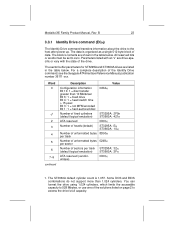
.... The data is 1,057. The sector buffer parameters for ST3295A and ST3660A drives are drive-specific or vary with the state of the Identify Drive command, see the Seagate ATA Interface Reference Manual, publication number 36111-xxx. All reserved bits or words must be set to the host after power up. Word 0 11 2 3 4 5 6 7-9 continued Description Value Configuration information Bit 10: 1 = disc transfer greater than 1,024 cylinders. You can format the drive using 1,024 cylinders...
.... The data is 1,057. The sector buffer parameters for ST3295A and ST3660A drives are drive-specific or vary with the state of the Identify Drive command, see the Seagate ATA Interface Reference Manual, publication number 36111-xxx. All reserved bits or words must be set to the host after power up. Word 0 11 2 3 4 5 6 7-9 continued Description Value Configuration information Bit 10: 1 = disc transfer greater than 1,024 cylinders. You can format the drive using 1,024 cylinders...
Product Manual
Page 34
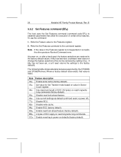
... set , a software reset does not change the feature selections (this can be canceled by the ST3295A and ST3660A drives. The following table shows alterable features supported by setting CCH). Byte Feature description 02H Enable write cache (factory default). 03H Set value for Set Transfer mode based on value in the Features register is not supported or is listed. Enable ECC (factory default). Write the Set Features command to the Features register. 2. At power-on read long/write long commands (factory default...
... set , a software reset does not change the feature selections (this can be canceled by the ST3295A and ST3660A drives. The following table shows alterable features supported by setting CCH). Byte Feature description 02H Enable write cache (factory default). 03H Set value for Set Transfer mode based on value in the Features register is not supported or is listed. Enable ECC (factory default). Write the Set Features command to the Features register. 2. At power-on read long/write long commands (factory default...
Product Manual
Page 35
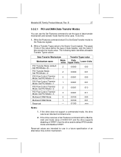
...future specification of an alternative flow-control mechanism. If the drive does not support a commanded mode, the drive returns an Aborted Command error. 2. If the drive receives a Set Features command with a Mechanism and mode value of 00000 001 and the drive supports disabling of data transfer mechanism and transfer mode that the drive uses. Write Set Features command value 03H (Set Data Transfer mode) to the Sector Count register. The following table identifies allowable Transfer Types values: Data Transfer Mechanism Mechanism name Mode value PIO Transfer Mode (default: Set...
...future specification of an alternative flow-control mechanism. If the drive does not support a commanded mode, the drive returns an Aborted Command error. 2. If the drive receives a Set Features command with a Mechanism and mode value of 00000 001 and the drive supports disabling of data transfer mechanism and transfer mode that the drive uses. Write Set Features command value 03H (Set Data Transfer mode) to the Sector Count register. The following table identifies allowable Transfer Types values: Data Transfer Mechanism Mechanism name Mode value PIO Transfer Mode (default: Set...
Product Manual
Page 36
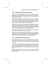
... the number of sectors per block to the default of 2, 4, 8 and 16 sectors. 28 Medalist XE Family Product Manual, Rev. If a block count is not supported, an Aborted Command error is issued, the Sector Count register contains the number of sectors (not the number of sectors per block. Interrupts are disabled. The number of blocks or the block count) requested. If Disable Default has been set to perform Read and Write Multiple operations and...
... the number of sectors per block to the default of 2, 4, 8 and 16 sectors. 28 Medalist XE Family Product Manual, Rev. If a block count is not supported, an Aborted Command error is issued, the Sector Count register contains the number of sectors (not the number of sectors per block. Interrupts are disabled. The number of blocks or the block count) requested. If Disable Default has been set to perform Read and Write Multiple operations and...
Product Manual
Page 39
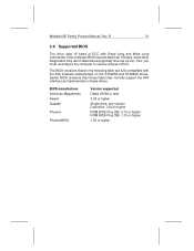
... following table are fully compatible with Read Long and Write Long commands. Earlier BIOS revisions than 16 bytes, some drive diagnostics may not fully support the ATA interface as implemented on the ST3295A and ST3660A drives. BIOS manufacturer American Megatrends Award Quadtel Phoenix PhoenixBIOS Version supported Dated 4/9/90 or later 3.04 or higher Single drive, any version Dual drive, 3.04 or higher ROM BIOS Plus 286, 3.10 or...
... following table are fully compatible with Read Long and Write Long commands. Earlier BIOS revisions than 16 bytes, some drive diagnostics may not fully support the ATA interface as implemented on the ST3295A and ST3660A drives. BIOS manufacturer American Megatrends Award Quadtel Phoenix PhoenixBIOS Version supported Dated 4/9/90 or later 3.04 or higher Single drive, any version Dual drive, 3.04 or higher ROM BIOS Plus 286, 3.10 or...


