Product Manual
Page 5
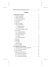
B iii Contents 1.0 Specification summary 1 1.1 Format configuration 1 1.2 Physical organization 2 1.3 Functional specifications 3 1.4 Drive dimensions 3 1.5 Seek time 3 1.6 Start and stop time 4 1.7 Power specifications 4 1.7.1 Voltage tolerances 4 1.7.2 Conducted noise 5 1.7.3 Power-management modes 5 1.8 Environment 7 1.8.1 Ambient ...2.2 The ATA interface connector 12 2.3 Power connector 12 2.4 Master/slave jumper block 12 2.4.1 Single-drive configuration 13 2.4.2 Two-drive configuration 13 2.4.3 Cable-select configuration 14 Medalist XE Family Product Manual, Rev.
B iii Contents 1.0 Specification summary 1 1.1 Format configuration 1 1.2 Physical organization 2 1.3 Functional specifications 3 1.4 Drive dimensions 3 1.5 Seek time 3 1.6 Start and stop time 4 1.7 Power specifications 4 1.7.1 Voltage tolerances 4 1.7.2 Conducted noise 5 1.7.3 Power-management modes 5 1.8 Environment 7 1.8.1 Ambient ...2.2 The ATA interface connector 12 2.3 Power connector 12 2.4 Master/slave jumper block 12 2.4.1 Single-drive configuration 13 2.4.2 Two-drive configuration 13 2.4.3 Cable-select configuration 14 Medalist XE Family Product Manual, Rev.
Product Manual
Page 6
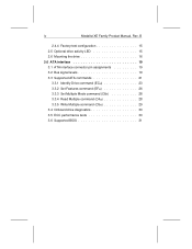
iv Medalist XE Family Product Manual, Rev. B 2.4.4 Factory-test configuration 15 2.5 Optional drive activity LED 15 2.6 Mounting the drive 16 3.0 ATA interface 19 3.1 ATA interface connector pin assignments 19 3.2 Bus signal levels 19 3.3 Supported ATA commands 21 3.3.1 Identify Drive command (ECH 23 3.3.2 Set Features command (EFH 26 3.3.3 Set Multiple Mode command (C6H 28 3.3.4 Read Multiple command (C4H 28 3.3.5 Write Multiple command (C5H 29 3.4 Onboard drive diagnostics 30 3.5 ECC performance tests 30 3.6 Supported BIOS 31
iv Medalist XE Family Product Manual, Rev. B 2.4.4 Factory-test configuration 15 2.5 Optional drive activity LED 15 2.6 Mounting the drive 16 3.0 ATA interface 19 3.1 ATA interface connector pin assignments 19 3.2 Bus signal levels 19 3.3 Supported ATA commands 21 3.3.1 Identify Drive command (ECH 23 3.3.2 Set Features command (EFH 26 3.3.3 Set Multiple Mode command (C6H 28 3.3.4 Read Multiple command (C4H 28 3.3.5 Write Multiple command (C5H 29 3.4 Onboard drive diagnostics 30 3.5 ECC performance tests 30 3.6 Supported BIOS 31
Product Manual
Page 7
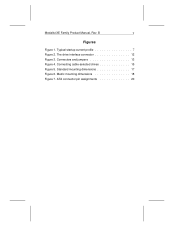
Connectors and jumpers 13 Figure 4. Metric mounting dimensions 18 Figure 7. B v Figures Figure 1. Connecting cable-selected drives 15 Figure 5. The drive interface connector 12 Figure 3. Typical startup current profile 7 Figure 2. Standard mounting dimensions 17 Figure 6. ATA connector pin assignments 20 Medalist XE Family Product Manual, Rev.
Connectors and jumpers 13 Figure 4. Metric mounting dimensions 18 Figure 7. B v Figures Figure 1. Connecting cable-selected drives 15 Figure 5. The drive interface connector 12 Figure 3. Typical startup current profile 7 Figure 2. Standard mounting dimensions 17 Figure 6. ATA connector pin assignments 20 Medalist XE Family Product Manual, Rev.
Product Manual
Page 9
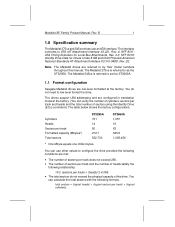
...is referred to as the ST3660A. 1.1 Format configuration Seagate Medalist drives are low-level formatted at the factory. (You can verify the number of cylinders, sectors per track) × (heads) ≤ 4,096. • The total sectors do not need to configure the drive provided the following conditions are... conforms to by their model numbers throughout this manual. Note. SFF 8011: ATA Timing Extension for Drives Under 8 GB and Draft Proposal American National Standards AT Attachment Interface X3.310-948D, Rev. 2E. ST3660A 1,057 16 63 545.5 1,065,456 You can calculate the total ...
...is referred to as the ST3660A. 1.1 Format configuration Seagate Medalist drives are low-level formatted at the factory. (You can verify the number of cylinders, sectors per track) × (heads) ≤ 4,096. • The total sectors do not need to configure the drive provided the following conditions are... conforms to by their model numbers throughout this manual. Note. SFF 8011: ATA Timing Extension for Drives Under 8 GB and Draft Proposal American National Standards AT Attachment Interface X3.310-948D, Rev. 2E. ST3660A 1,057 16 63 545.5 1,065,456 You can calculate the total ...
Product Manual
Page 10
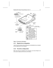
... to the drive's full capacity to install the drive. 1.2 Physical organization Heads Discs ST3295A 2 1 ST3660A 4 2 B Note. In an overwrap condition, only the overwrapping cylinders are used to 528 Mbytes. 2 Medalist XE Family Product Manual, Rev. ...These systems do not acknowledge more than 528 Mbytes. • Use installation software or a software device driver that supports more than 1,024 cylinders are several solutions for 17.3 Mbytes. Some DOS and BIOS pairings can limit the accessible hard disc capacity to determine the drive...
... to the drive's full capacity to install the drive. 1.2 Physical organization Heads Discs ST3295A 2 1 ST3660A 4 2 B Note. In an overwrap condition, only the overwrapping cylinders are used to 528 Mbytes. 2 Medalist XE Family Product Manual, Rev. ...These systems do not acknowledge more than 528 Mbytes. • Use installation software or a software device driver that supports more than 1,024 cylinders are several solutions for 17.3 Mbytes. Some DOS and BIOS pairings can limit the accessible hard disc capacity to determine the drive...
Product Manual
Page 11
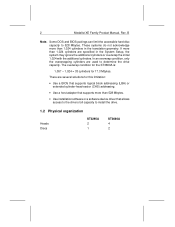
The measurements are taken using nominal power at sea level and at least 5,000 measurements of seeks between random tracks, less overhead. Medalist XE Family Product Manual, Rev. B 3 1.3 Functional specifications Interface Internal data transfer rate (Mbits/sec) External data transfer rate (Mbytes/sec) PIO Mode 3 DMA ...: • Track-to 35.8 11.1* 13.3* 3,811 120 RLL (1,7) 512 63,225 42,150 3,285 * Represents the external burst data transfer rate. 1.4 Drive dimensions Height (max) Width (max) Depth (max) Weight (max) 1.00 inch (25.4 mm) 4.02 inches (102.1 mm) 5.77 inches (146.6 mm...
The measurements are taken using nominal power at sea level and at least 5,000 measurements of seeks between random tracks, less overhead. Medalist XE Family Product Manual, Rev. B 3 1.3 Functional specifications Interface Internal data transfer rate (Mbits/sec) External data transfer rate (Mbytes/sec) PIO Mode 3 DMA ...: • Track-to 35.8 11.1* 13.3* 3,811 120 RLL (1,7) 512 63,225 42,150 3,285 * Represents the external burst data transfer rate. 1.4 Drive dimensions Height (max) Width (max) Depth (max) Weight (max) 1.00 inch (25.4 mm) 4.02 inches (102.1 mm) 5.77 inches (146.6 mm...
Product Manual
Page 12
...Stop time Typical 7 sec 6 sec Maximum 10 sec 9 sec 1.7 Power specifications Except during a write operation, you can apply power to the drive or remove power from the first data cylinder to the maximum data cylinder and back to -track Average Full-stroke Latency typ (msec) typ (...msec) typ (msec) (msec) ST3295A 5 ST3660A 5 14 34 7.87 14 34 7.87 1.6 Start and stop times are shown in both directions. Model Track-to the first data cylinder. 4 Medalist XE Family Product Manual, Rev. See Figure 1 on page 7 for the typical startup current profile....
...Stop time Typical 7 sec 6 sec Maximum 10 sec 9 sec 1.7 Power specifications Except during a write operation, you can apply power to the drive or remove power from the first data cylinder to the maximum data cylinder and back to -track Average Full-stroke Latency typ (msec) typ (...msec) typ (msec) (msec) ST3295A 5 ST3660A 5 14 34 7.87 14 34 7.87 1.6 Start and stop times are shown in both directions. Model Track-to the first data cylinder. 4 Medalist XE Family Product Manual, Rev. See Figure 1 on page 7 for the typical startup current profile....
Product Manual
Page 13
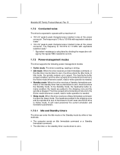
..., or the standby timer has counted down to the Active mode whenever a seek, read or write operation is stopped. A hard reset or a soft reset returns the drive to zero. The frequency is 100 KHz to 10 MHz with equivalent resistive loads.* • 100 mV peak-to -peak ... in the shipping zone and the spindle is needed . • Sleep mode. When the drive receives a Sleep Immediate command, it enters the Sleep mode. Medalist XE Family Product Manual, Rev. B 5 1.7.2 Conducted noise The drive is 10 Hz to the Active mode whenever a seek, read or write operation is at ...
..., or the standby timer has counted down to the Active mode whenever a seek, read or write operation is stopped. A hard reset or a soft reset returns the drive to zero. The frequency is 100 KHz to 10 MHz with equivalent resistive loads.* • 100 mV peak-to -peak ... in the shipping zone and the spindle is needed . • Sleep mode. When the drive receives a Sleep Immediate command, it enters the Sleep mode. Medalist XE Family Product Manual, Rev. B 5 1.7.2 Conducted noise The drive is 10 Hz to the Active mode whenever a seek, read or write operation is at ...
Product Manual
Page 14
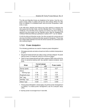
...is enabled. There may be a slight delay between each time the drive completes a read, write or seek. See the Seagate ATA Interface Reference Manual, publication number 36111-xxx for details. the peak startup power is ...setup utility to measure power dissipation: • All measurements are taken using an RMS meter while the drive is measured using the nominal voltages. • Seek current measurements are used to enable and set the... 3.34 1.865 0.725 0.650 1. To enable power management, use the computer setup utility. 2. 6 Medalist XE Family Product Manual, Rev.
...is enabled. There may be a slight delay between each time the drive completes a read, write or seek. See the Seagate ATA Interface Reference Manual, publication number 36111-xxx for details. the peak startup power is ...setup utility to measure power dissipation: • All measurements are taken using an RMS meter while the drive is measured using the nominal voltages. • Seek current measurements are used to enable and set the... 3.34 1.865 0.725 0.650 1. To enable power management, use the computer setup utility. 2. 6 Medalist XE Family Product Manual, Rev.
Product Manual
Page 15
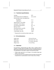
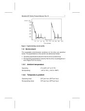
Typical startup current profile 1.8 Environment The acceptable environmental conditions for the drive are defined as follows: • Operating specifications assume that the drive is powered up. • Nonoperating specifications assume that the drive is packaged as it was shipped from the factory. 1.8.1 Ambient temperature Operating...;F per hour) 30°C per hour (54°F per hour) The specifications in this section are specified below. Medalist XE Family Product Manual, Rev. B 7 Current mA 1,200 1,000 800 600 400 200 2.0 4.0 6.0 8.0 10.0 12.0 14.0 16.0 18.0 20.0 Time ...
Typical startup current profile 1.8 Environment The acceptable environmental conditions for the drive are defined as follows: • Operating specifications assume that the drive is powered up. • Nonoperating specifications assume that the drive is packaged as it was shipped from the factory. 1.8.1 Ambient temperature Operating...;F per hour) 30°C per hour (54°F per hour) The specifications in this section are specified below. Medalist XE Family Product Manual, Rev. B 7 Current mA 1,200 1,000 800 600 400 200 2.0 4.0 6.0 8.0 10.0 12.0 14.0 16.0 18.0 20.0 Time ...

Product Manual
Page 16
...pressure, max 29 dBA 33 dBA The specifications in the shipping zone and the drive sustains no physical damage, but performance is measured at idle from 1 meter above the drive top cover. 8 Medalist XE Family Product Manual, Rev. Shock 5-22 Hz vibration 22-300 Hz vibration Normal operating Abnormal operating ...Shock and vibration Shock measurements are in the table below are defined as follows: • During normal operating shock and vibration, the drive sustains no physical damage and reads and writes data without errors. • During abnormal operating shock and vibration, the...
...pressure, max 29 dBA 33 dBA The specifications in the shipping zone and the drive sustains no physical damage, but performance is measured at idle from 1 meter above the drive top cover. 8 Medalist XE Family Product Manual, Rev. Shock 5-22 Hz vibration 22-300 Hz vibration Normal operating Abnormal operating ...Shock and vibration Shock measurements are in the table below are defined as follows: • During normal operating shock and vibration, the drive sustains no physical damage and reads and writes data without errors. • During abnormal operating shock and vibration, the...
Product Manual
Page 17
...device). Operation with an ambient temperature of the FCC rules. Medalist XE Family Product Manual, Rev. The heads park inside the maximum data cylinder....listings This drive is required. When power is applied, the heads recalibrate to Subpart J of Part 15 of 25°C. As such, a drive is likely... to result in an enclosure as described above to ensure that the total assembly (enclosure, disc drive, motherboard, power supply,...The ST3295A and ST3660A drives are intended to be a subassembly even when individually marketed to radio and television...
...device). Operation with an ambient temperature of the FCC rules. Medalist XE Family Product Manual, Rev. The heads park inside the maximum data cylinder....listings This drive is required. When power is applied, the heads recalibrate to Subpart J of Part 15 of 25°C. As such, a drive is likely... to result in an enclosure as described above to ensure that the total assembly (enclosure, disc drive, motherboard, power supply,...The ST3295A and ST3660A drives are intended to be a subassembly even when individually marketed to radio and television...
Product Manual
Page 18
... computer are encouraged to try one side or the other of the following booklet prepared by turning the equipment on different branch outlets. 10 Medalist XE Family Product Manual, Rev. If this equipment does cause interference to radio or television, which can be determined by the Federal Communications Commission: How to provide...
... computer are encouraged to try one side or the other of the following booklet prepared by turning the equipment on different branch outlets. 10 Medalist XE Family Product Manual, Rev. If this equipment does cause interference to radio or television, which can be determined by the Federal Communications Commission: How to provide...
Product Manual
Page 19
... do, you install it in a computer, be careful not to the drive while it is in the computer. • Do not touch the connector pins or the printed circuit board. Medalist XE Family Product Manual, Rev. B 11 2.0 Configuration and mounting This section discusses the ATA ...interface connector and other physical features of a power supply that is plugged into a grounded outlet when handling the drive and throughout the entire installation procedure....
... do, you install it in a computer, be careful not to the drive while it is in the computer. • Do not touch the connector pins or the printed circuit board. Medalist XE Family Product Manual, Rev. B 11 2.0 Configuration and mounting This section discusses the ATA ...interface connector and other physical features of a power supply that is plugged into a grounded outlet when handling the drive and throughout the entire installation procedure....
Product Manual
Page 20
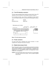
12 Medalist XE Family Product Manual, Rev. For the mating connector, use Seagate part number 10562-001 or an equivalent. If you may damage the jumper block and the jumper. If you use a jumper that is not the ... jumpers, use a 40-pin, nonshielded connector with 2 rows of 20 male pins. The jumper block accepts 2-mm (0.079-inch) jumpers. Caution. The drive interface connector 2.3 Power connector The drive comes with a standard 3-pin power connector. 2.4 Master/slave jumper block Figure 3 shows the location of the master/slave jumper block and shows how...
12 Medalist XE Family Product Manual, Rev. For the mating connector, use Seagate part number 10562-001 or an equivalent. If you may damage the jumper block and the jumper. If you use a jumper that is not the ... jumpers, use a 40-pin, nonshielded connector with 2 rows of 20 male pins. The jumper block accepts 2-mm (0.079-inch) jumpers. Caution. The drive interface connector 2.3 Power connector The drive comes with a standard 3-pin power connector. 2.4 Master/slave jumper block Figure 3 shows the location of the master/slave jumper block and shows how...
Product Manual
Page 21
... the master and the other as the slave. a slave is present, but it is no slave. Medalist XE Family Product Manual, Rev. the slave is either a Medalist family drive or another ATA-compatible drive, or there is not ATA-compatible. B 13 4-pin power connector 1234 Circuit board +5V +5V return +12V return +12V Front 2-pin...
... the master and the other as the slave. a slave is present, but it is no slave. Medalist XE Family Product Manual, Rev. the slave is either a Medalist family drive or another ATA-compatible drive, or there is not ATA-compatible. B 13 4-pin power connector 1234 Circuit board +5V +5V return +12V return +12V Front 2-pin...
Product Manual
Page 22
14 Medalist XE Family Product Manual, Rev. You can configure the Medalist drive for a slave that is installed in this position, the drive ignores the jumper installed on page 13. When a jumper is : • An ATA-compatible drive • A non-ATA-compatible drive that has pin 28 unconnected (CSEL is ready 2.4.2.2 Medalist drive as the master when used with a non...
14 Medalist XE Family Product Manual, Rev. You can configure the Medalist drive for a slave that is installed in this position, the drive ignores the jumper installed on page 13. When a jumper is : • An ATA-compatible drive • A non-ATA-compatible drive that has pin 28 unconnected (CSEL is ready 2.4.2.2 Medalist drive as the master when used with a non...
Product Manual
Page 23
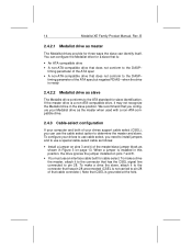
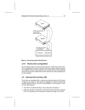
...drive at the factory. When jumpers are installed in Figure 3 on the printed circuit board, or • A two-pin header is used to pin 28 of these positions, the heads continuously seek back and forth across the media and the drive... ignores all control signals sent by the interface. 2.5 Optional drive activity LED The drives are two LED options: • The... and 6 and pins 7 and 8 at computer Computer Figure 4. Connecting cable-selected drives 2.4.4 Factory-test configuration Do not install jumpers on the printed circuit board for whom the...
...drive at the factory. When jumpers are installed in Figure 3 on the printed circuit board, or • A two-pin header is used to pin 28 of these positions, the heads continuously seek back and forth across the media and the drive... ignores all control signals sent by the interface. 2.5 Optional drive activity LED The drives are two LED options: • The... and 6 and pins 7 and 8 at computer Computer Figure 4. Connecting cable-selected drives 2.4.4 Factory-test configuration Do not install jumpers on the printed circuit board for whom the...
Product Manual
Page 24
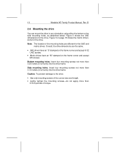
... the mounting screws-do not apply more than 0.20 inches (6 full turns) into the drive frame. B 2.6 Mounting the drive You can mount the drive in any orientation using either the bottom or the side mounting holes, as described below. Figure... 6 on the frame runner and accept M3 screws. Insert four mounting screws not more than 0.13 inches (4 full turns) into the drive frame. Note. Overall, the drive dimensions are different for the drive. 16 Medalist XE Family Product Manual...
... the mounting screws-do not apply more than 0.20 inches (6 full turns) into the drive frame. B 2.6 Mounting the drive You can mount the drive in any orientation using either the bottom or the side mounting holes, as described below. Figure... 6 on the frame runner and accept M3 screws. Insert four mounting screws not more than 0.13 inches (4 full turns) into the drive frame. Note. Overall, the drive dimensions are different for the drive. 16 Medalist XE Family Product Manual...
Product Manual
Page 25
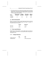
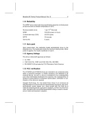
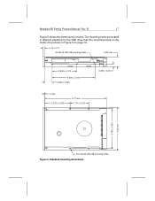
The mounting holes are located in different positions for the SAE drive than the mounting holes on the metric drive shown in inches. Standard mounting dimensions Medalist XE Family Product Manual, Rev. B 17 Figure 5 shows the dimensions in Figure 6 on page 18. 0.15 ± 0.01 Six #6-32 UNC-2B mounting holes 1.000 max 2.362 ± 0.010 4.000 ± 0.010 0.630 ± 0.025 0.030 2.375 ± 0.025 5.77 max 1.75 ± 0.010 0.250 ± 0.010 3.750± 0.030 4.02 max Four #6-32 UNC-2B mounting holes Figure 5.
The mounting holes are located in different positions for the SAE drive than the mounting holes on the metric drive shown in inches. Standard mounting dimensions Medalist XE Family Product Manual, Rev. B 17 Figure 5 shows the dimensions in Figure 6 on page 18. 0.15 ± 0.01 Six #6-32 UNC-2B mounting holes 1.000 max 2.362 ± 0.010 4.000 ± 0.010 0.630 ± 0.025 0.030 2.375 ± 0.025 5.77 max 1.75 ± 0.010 0.250 ± 0.010 3.750± 0.030 4.02 max Four #6-32 UNC-2B mounting holes Figure 5.
