
Owner's Manual
Page 2
...contains all the information you need to operate and enjoy your way to rely on -board digital computer enables you for making the Schwinn® bike a part of fitness. For years to come, you pursue your exercise and fitness activities. So let's get started in its entirety before ...getting started . Please read this Schwinn® bike is designed to be able to a slimmer and healthier body. CONGRATULATIONS! Thank you to achieve an ...
...contains all the information you need to operate and enjoy your way to rely on -board digital computer enables you for making the Schwinn® bike a part of fitness. For years to come, you pursue your exercise and fitness activities. So let's get started in its entirety before ...getting started . Please read this Schwinn® bike is designed to be able to a slimmer and healthier body. CONGRATULATIONS! Thank you to achieve an ...
Owner's Manual
Page 4
...19.7 inches ( 0.5 m) on exercise equipment, and parents and others in this machine for a user weight limit of the machine. This machine contains moving parts. Set up and operate this machine. 3. Make sure that all sides of 300 lb. (136 kg). Read and understand the complete Owner's Manual. ... away from this manual: Indicates a potentially hazardous situation which, if not avoided, could result in this manual. This machine is designed for loose parts or signs of this weight. 11. Inspect this condition. Pay special attention to the seat, pedals, and crank arms. Do not use if ...
...19.7 inches ( 0.5 m) on exercise equipment, and parents and others in this machine for a user weight limit of the machine. This machine contains moving parts. Set up and operate this machine. 3. Make sure that all sides of 300 lb. (136 kg). Read and understand the complete Owner's Manual. ... away from this manual: Indicates a potentially hazardous situation which, if not avoided, could result in this manual. This machine is designed for loose parts or signs of this weight. 11. Inspect this condition. Pay special attention to the seat, pedals, and crank arms. Do not use if ...
Owner's Manual
Page 30
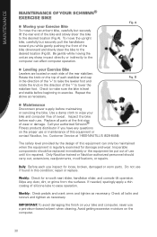
...examined for smooth seat slider, handlebar slider, and console tilt operation. Wipe any questions on the top of each use . Check all parts at 1-800-NAUTILUS (628-8458). Be gentle while moving the unit as necessary. Do not use until it is level and stable ...SCHWINN® EXERCISE BIKE Moving your Exercise Bike To move the upright bike, carefully but securely lift the rear end of the bike and slowly steer the bike to the desired location (Fig A). Use a damp cloth to wipe your bike and computer free of silicone lube to ease operation. To move the recumbent bike...
...examined for smooth seat slider, handlebar slider, and console tilt operation. Wipe any questions on the top of each use . Check all parts at 1-800-NAUTILUS (628-8458). Be gentle while moving the unit as necessary. Do not use until it is level and stable ...SCHWINN® EXERCISE BIKE Moving your Exercise Bike To move the upright bike, carefully but securely lift the rear end of the bike and slowly steer the bike to the desired location (Fig A). Use a damp cloth to wipe your bike and computer free of silicone lube to ease operation. To move the recumbent bike...

Owner's Manual
Page 32
..., make sure that it in your daily planner just as possible, so you hoped for fitness, and make sure these things are accessible. Make fitness a part of heart disease in . Set goals. Research has shown that you have done in your family. don't overdo it in 90 days or a year? 32...
..., make sure that it in your daily planner just as possible, so you hoped for fitness, and make sure these things are accessible. Make fitness a part of heart disease in . Set goals. Research has shown that you have done in your family. don't overdo it in 90 days or a year? 32...

Owner's Manual
Page 34
... as reaching for your flexibility, you wake up in the morning. Don't just do body weight exercises such as push-ups or lunges. The best part is recommended that consistent strength training helps maintain bone and muscle mass as we perform daily tasks, play or exercise. You can use elastic tubing...
... as reaching for your flexibility, you wake up in the morning. Don't just do body weight exercises such as push-ups or lunges. The best part is recommended that consistent strength training helps maintain bone and muscle mass as we perform daily tasks, play or exercise. You can use elastic tubing...
Owner's Manual
Page 42
...is structurally defective with a new frame or replace the unit with a unit of the exercise product in lieu of the parts supplier. 2. or an Authorized Schwinn® Fitness Dealer, or use of someone other warranties not expressly set forth by Nautilus, Inc., Nautilus, Inc. will ...repair an exercise product or part yourself, using the services of such unauthorized service or parts. 6. will have the option to be performed by the use a replacement part not supplied by Schwinn® Fitness warranty policies and procedures. See your Authorized Schwinn® Fitness Dealer for ...
...is structurally defective with a new frame or replace the unit with a unit of the exercise product in lieu of the parts supplier. 2. or an Authorized Schwinn® Fitness Dealer, or use of someone other warranties not expressly set forth by Nautilus, Inc., Nautilus, Inc. will ...repair an exercise product or part yourself, using the services of such unauthorized service or parts. 6. will have the option to be performed by the use a replacement part not supplied by Schwinn® Fitness warranty policies and procedures. See your Authorized Schwinn® Fitness Dealer for ...

Assembly Manual
Page 2
CONTENTS Table of Contents Hardware 2 Exploded View 4 Parts List 5 Assembly Instructions 6 Important Contact Numbers 22 1
CONTENTS Table of Contents Hardware 2 Exploded View 4 Parts List 5 Assembly Instructions 6 Important Contact Numbers 22 1
Assembly Manual
Page 3
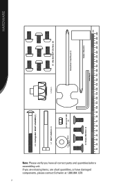
If you have damaged components, please contact Schwinn at 1.800.864.1270 2 I-13 Carriage Bolt M8xP1.25x85MM (1) I-1 M8xP1.25x85mm I-2 Knob (1) I-5 Allen Bolt M8xP1.25x16mm (9) I-11 Regular Washer 10*25*2t(1) I-4 lock nut for M8 (1) Screwdriver I-6 Screws M8x16mm Socket Wrench���� Allen Key���� ���� SW231 HARDWARE Note: Please verify you are missing items, are short quantities, or have all correct parts and quantities before assembling unit.
If you have damaged components, please contact Schwinn at 1.800.864.1270 2 I-13 Carriage Bolt M8xP1.25x85MM (1) I-1 M8xP1.25x85mm I-2 Knob (1) I-5 Allen Bolt M8xP1.25x16mm (9) I-11 Regular Washer 10*25*2t(1) I-4 lock nut for M8 (1) Screwdriver I-6 Screws M8x16mm Socket Wrench���� Allen Key���� ���� SW231 HARDWARE Note: Please verify you are missing items, are short quantities, or have all correct parts and quantities before assembling unit.
Assembly Manual
Page 4
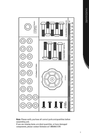
If you have damaged components, please contact Schwinn at 1.800.864.1270 3 I-3 Flat Washer 8*16*2t(20) I-12 Regular Washer 12.5*20*2t(1) I-8 Screw M5*16MM (4) I-10 Knob (1) I-7 Allen Bolt M8xP1.0x45mm (4) I-9 Allen Bolt M8xP1.0x35mm (5) ���� HARDWARE Note: Please verify you are missing items, are short quantities, or have all correct parts and quantities before assembling unit.
If you have damaged components, please contact Schwinn at 1.800.864.1270 3 I-3 Flat Washer 8*16*2t(20) I-12 Regular Washer 12.5*20*2t(1) I-8 Screw M5*16MM (4) I-10 Knob (1) I-7 Allen Bolt M8xP1.0x45mm (4) I-9 Allen Bolt M8xP1.0x35mm (5) ���� HARDWARE Note: Please verify you are missing items, are short quantities, or have all correct parts and quantities before assembling unit.
Assembly Manual
Page 6
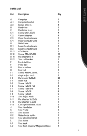
... Carriage Bolt M8x1.25x85 1 J Seat Handlebar 1 K Seat Frame 1 K-1 Seat bottom 1 K-2 Water bottle holder 1 K-3 Seat adjustment knob 1 L Seat frame 1 L-1 Seat back 1 L-2 Seat Back Cover w/ Magazine Holder 1 5 PARTS LIST PARTS LIST Ref.
... Carriage Bolt M8x1.25x85 1 J Seat Handlebar 1 K Seat Frame 1 K-1 Seat bottom 1 K-2 Water bottle holder 1 K-3 Seat adjustment knob 1 L Seat frame 1 L-1 Seat back 1 L-2 Seat Back Cover w/ Magazine Holder 1 5 PARTS LIST PARTS LIST Ref.
Assembly Manual
Page 8
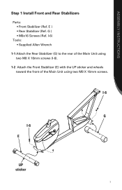
I-6) Tools: • Supplied Allen Wrench 1-1 Attach the Rear Stabilizer (G) to the rear of the Main Unit using two M8 X 16mm screws (I -6 E UP sticker 7 E ) • Rear Stabilizer (Ref. G ) • M8x16 Screws (Ref. ASSEMBLY INSTRUCTIONS Step 1 Install Front and Rear Stabilizers Parts: • Front Stabilizer (Ref. I-6 G I -6). 1-2 Attach the Front Stabilizer (E) with the UP sticker and wheels toward the front of the Main Unit using two M8 X 16mm screws.
I-6) Tools: • Supplied Allen Wrench 1-1 Attach the Rear Stabilizer (G) to the rear of the Main Unit using two M8 X 16mm screws (I -6 E UP sticker 7 E ) • Rear Stabilizer (Ref. G ) • M8x16 Screws (Ref. ASSEMBLY INSTRUCTIONS Step 1 Install Front and Rear Stabilizers Parts: • Front Stabilizer (Ref. I-6 G I -6). 1-2 Attach the Front Stabilizer (E) with the UP sticker and wheels toward the front of the Main Unit using two M8 X 16mm screws.
Assembly Manual
Page 9
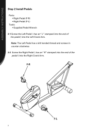
F-R F-L 8 ASSEMBLY INSTRUCTIONS Step 2 Install Pedals Parts: • Right Pedal (F-R) • Right Pedal (F-L) Tools: • Supplied Pedal Wrench 2-1 Screw the Left Pedal ( has an "L" stamped into the end of the pedal ) into the Left Crank Arm. Note: The Left Pedal has a left handed thread and screws in counter clockwise. 2-2 Screw the Right Pedal ( has an "R "stamped into the end of the pedal ) into the Right Crank Arm.
F-R F-L 8 ASSEMBLY INSTRUCTIONS Step 2 Install Pedals Parts: • Right Pedal (F-R) • Right Pedal (F-L) Tools: • Supplied Pedal Wrench 2-1 Screw the Left Pedal ( has an "L" stamped into the end of the pedal ) into the Left Crank Arm. Note: The Left Pedal has a left handed thread and screws in counter clockwise. 2-2 Screw the Right Pedal ( has an "R "stamped into the end of the pedal ) into the Right Crank Arm.
Assembly Manual
Page 10
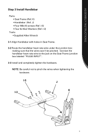
K) • Handlebar (Ref. I -3 9 ASSEMBLY INSTRUCTIONS Step 3 Install Handlebar Parts: • Seat Frame (Ref. Connect the handlebar heart rate wire to pinch the wires when tightening the hardware. J) • Four M8x16 screws (Ref. I-5 J K I -3) Tools: • ...
K) • Handlebar (Ref. I -3 9 ASSEMBLY INSTRUCTIONS Step 3 Install Handlebar Parts: • Seat Frame (Ref. Connect the handlebar heart rate wire to pinch the wires when tightening the hardware. J) • Four M8x16 screws (Ref. I-5 J K I -3) Tools: • ...

Assembly Manual
Page 11
ASSEMBLY INSTRUCTIONS Step 4 Install Bottle Holder Parts: • Water Bottle Holder (Ref. K-1 K-2 I -8) • Seat Bottom (Ref. K-2) • Four M5x16 Screws (Ref. K-1) Tools: • Supplied Phillips Head Screwdriver 4-1 Align the Water Bottle Holder under the left side of the Seat Bottom. 4-2 Install and completely tighten the hardware. I -8 10
ASSEMBLY INSTRUCTIONS Step 4 Install Bottle Holder Parts: • Water Bottle Holder (Ref. K-1 K-2 I -8) • Seat Bottom (Ref. K-2) • Four M5x16 Screws (Ref. K-1) Tools: • Supplied Phillips Head Screwdriver 4-1 Align the Water Bottle Holder under the left side of the Seat Bottom. 4-2 Install and completely tighten the hardware. I -8 10

Assembly Manual
Page 12
K-1 K I-3 I -7) • Four 8x16x2 Washers (Ref. I -7 11 I-3) Tools: • Supplied Allen Wrench 5-1 Align the Seat Bottom (K-1) with the Seat Frame (K). 5-2 Install and completely tighten the hardware. K-1) • Four M8x1x45 Screws (Ref. ASSEMBLY INSTRUCTIONS Step 5 Install Seat Bottom Parts: • Seat Bottom (Ref.
K-1 K I-3 I -7) • Four 8x16x2 Washers (Ref. I -7 11 I-3) Tools: • Supplied Allen Wrench 5-1 Align the Seat Bottom (K-1) with the Seat Frame (K). 5-2 Install and completely tighten the hardware. K-1) • Four M8x1x45 Screws (Ref. ASSEMBLY INSTRUCTIONS Step 5 Install Seat Bottom Parts: • Seat Bottom (Ref.
Assembly Manual
Page 13
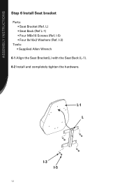
L) • Seat Back (Ref L-1) • Four M8x16 Screws (Ref. ASSEMBLY INSTRUCTIONS Step 6 Install Seat bracket Parts: • Seat Bracket (Ref. I -3) Tools: • Supplied Allen Wrench 6-1 Align the Seat Bracket(L) with the Seat Back (L-1). 6-2 Install and completely tighten the hardware. I -5) • Four 8x16x2 Washers (Ref. L-1 L I-3 I-5 12
L) • Seat Back (Ref L-1) • Four M8x16 Screws (Ref. ASSEMBLY INSTRUCTIONS Step 6 Install Seat bracket Parts: • Seat Bracket (Ref. I -3) Tools: • Supplied Allen Wrench 6-1 Align the Seat Bracket(L) with the Seat Back (L-1). 6-2 Install and completely tighten the hardware. I -5) • Four 8x16x2 Washers (Ref. L-1 L I-3 I-5 12
Assembly Manual
Page 14
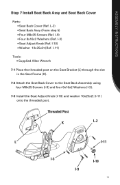
... Knob (Ref. L-2) • Seat Back Assy (From step 5) • Four M8x35 Screws (Ref. I -9 13 ASSEMBLY INSTRUCTIONS Step 7 Install Seat Back Assy and Seat Back Cover Parts: • Seat Back Cover (Ref. I -10) • Washer 10x25x2t (Ref. I -9) • Four 8x16x2 Washers (Ref. I-11) Tools: • Supplied Allen Wrench 7-1 Place the threaded post...
... Knob (Ref. L-2) • Seat Back Assy (From step 5) • Four M8x35 Screws (Ref. I -9 13 ASSEMBLY INSTRUCTIONS Step 7 Install Seat Back Assy and Seat Back Cover Parts: • Seat Back Cover (Ref. I -10) • Washer 10x25x2t (Ref. I -9) • Four 8x16x2 Washers (Ref. I-11) Tools: • Supplied Allen Wrench 7-1 Place the threaded post...
Assembly Manual
Page 16
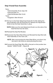
... (M) to lock the Seat Assembly in place. D-22) Tools: • Supplied Allen Wrench 9-1 Pull out on the main unit. ASSEMBLY INSTRUCTIONS Step 9 Install Seat Assembly Parts: • Seat Assembly (From step 3-6) • Seat Rail (Ref. NOTE: Make sure the seat Adjustment Knob is on the side of the Seat Rail that...
... (M) to lock the Seat Assembly in place. D-22) Tools: • Supplied Allen Wrench 9-1 Pull out on the main unit. ASSEMBLY INSTRUCTIONS Step 9 Install Seat Assembly Parts: • Seat Assembly (From step 3-6) • Seat Rail (Ref. NOTE: Make sure the seat Adjustment Knob is on the side of the Seat Rail that...
Assembly Manual
Page 17
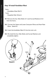
ASSEMBLY INSTRUCTIONS Step 10 Install Handlebar Mast Parts: • Handlebar Mast (Ref C) Tools: • Supplied Allen Wrench 10-1 Remove the four Allen Bolts (C-1) and Curved Washers (C-2) from the frame . 10-2 Connect the Upper and Lower Computer Wires and Heart Rate Wires. (Detail A) 10-3 Insert the Handlebar Mast (C) into the main unit. 10-4 Re-install the four Allen Bolts and Curved Washers and completely tighten. C Detail A C-2 C-1 16
ASSEMBLY INSTRUCTIONS Step 10 Install Handlebar Mast Parts: • Handlebar Mast (Ref C) Tools: • Supplied Allen Wrench 10-1 Remove the four Allen Bolts (C-1) and Curved Washers (C-2) from the frame . 10-2 Connect the Upper and Lower Computer Wires and Heart Rate Wires. (Detail A) 10-3 Insert the Handlebar Mast (C) into the main unit. 10-4 Re-install the four Allen Bolts and Curved Washers and completely tighten. C Detail A C-2 C-1 16

Assembly Manual
Page 18
ASSEMBLY INSTRUCTIONS Step 11 Install Handlebar Parts: • Handlebar (Ref B) • Washer (Ref I-3) • Screw M8x16 (Ref I-5) 11-1 Tuck the Computer Wires into the Mast to allow insertion of the Handlebar . 11-2 Slide the Handlebar (B) into the Mast and secure with the Console M8x16 Screw (I-5) and Washer (I-3) . (Figure A) 11-3 Pull the Computer Wires back up through the Handlebar as shown. (Figure B) B I-3 I-5 Figure B Figure A 17
ASSEMBLY INSTRUCTIONS Step 11 Install Handlebar Parts: • Handlebar (Ref B) • Washer (Ref I-3) • Screw M8x16 (Ref I-5) 11-1 Tuck the Computer Wires into the Mast to allow insertion of the Handlebar . 11-2 Slide the Handlebar (B) into the Mast and secure with the Console M8x16 Screw (I-5) and Washer (I-3) . (Figure A) 11-3 Pull the Computer Wires back up through the Handlebar as shown. (Figure B) B I-3 I-5 Figure B Figure A 17


