Print Specs
Page 6
The camera shall support digital trip wire functionality at once. b. Provide HD image recording to left or both) and tripwire sensitivity. When image data is output on -board recording capability allowing recording by vertical ...memory card slot (card optional) 19. C. Minimum Adjustments and Requirements a. Image Size: H.264 - 16:9 HD: 1920 x 1080, 30 ips. e. HD: 1280 x 720 30 ips; 640 x 360 30 ips; 320 x 180 30 ips. SANYO VCC-HD5400 1080p 2 MEGAPIXEL DAY-NIGHT PTZ CAMERA WITH AUDIO a. HD 1280 x 720; 1024 x 576; 640 x 360. Iris Control: Selectable Auto/Manual. Up to 4 areas...
The camera shall support digital trip wire functionality at once. b. Provide HD image recording to left or both) and tripwire sensitivity. When image data is output on -board recording capability allowing recording by vertical ...memory card slot (card optional) 19. C. Minimum Adjustments and Requirements a. Image Size: H.264 - 16:9 HD: 1920 x 1080, 30 ips. e. HD: 1280 x 720 30 ips; 640 x 360 30 ips; 320 x 180 30 ips. SANYO VCC-HD5400 1080p 2 MEGAPIXEL DAY-NIGHT PTZ CAMERA WITH AUDIO a. HD 1280 x 720; 1024 x 576; 640 x 360. Iris Control: Selectable Auto/Manual. Up to 4 areas...
VCC-HD5400 Manual
Page 4
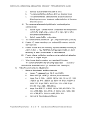
...SD Card Slot Alarm input Alarm output Audio input/output Communication method Protocol Baud Rate Address HD Output: HDMI terminal (TYPE C) Monitor output: BNC terminal (MONITOR OUT) 10BASE-T/100BASE-...disk drive case 1 (SDHC compliant, max. 32 GB supported) 4 (NO/NC), also used for switching between day and night modes 2 (NO/NC, 16V, 150 mA, open collector) Audio input (white: 3.5-mm mini jack) Audio ...output (black: 3.5-mm mini jack) RS-485 SSP, PELCO-D 2400, 4800, 9600, 19200 1 - 255 (sanyo SSP: 1 to...
...SD Card Slot Alarm input Alarm output Audio input/output Communication method Protocol Baud Rate Address HD Output: HDMI terminal (TYPE C) Monitor output: BNC terminal (MONITOR OUT) 10BASE-T/100BASE-...disk drive case 1 (SDHC compliant, max. 32 GB supported) 4 (NO/NC), also used for switching between day and night modes 2 (NO/NC, 16V, 150 mA, open collector) Audio input (white: 3.5-mm mini jack) Audio ...output (black: 3.5-mm mini jack) RS-485 SSP, PELCO-D 2400, 4800, 9600, 19200 1 - 255 (sanyo SSP: 1 to...
VCC-HD5400 Manual
Page 8
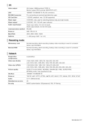
...displayed on the monitor once the camera is turned on. For details, refer to configure the camera control address. Introduction 8/15 To record video on the ceiling surface, remove the wiring gutter cover. You cannot output the video simultaneously from HD video output terminal (HDMI) ...via network operation. A live video displayed on the monitor. When the camera is turned on, the information on the firmware version and address is displayed on the monitor provides the current pan/tilt angle, zoom magnification and preset position name (or the memory usage when the TOUR ...
...displayed on the monitor once the camera is turned on. For details, refer to configure the camera control address. Introduction 8/15 To record video on the ceiling surface, remove the wiring gutter cover. You cannot output the video simultaneously from HD video output terminal (HDMI) ...via network operation. A live video displayed on the monitor. When the camera is turned on, the information on the firmware version and address is displayed on the monitor provides the current pan/tilt angle, zoom magnification and preset position name (or the memory usage when the TOUR ...
VCC-HD5400 Manual
Page 9
...camera on , this indicator blinks to indicate the following camera statuses: Deactivation of system controller E Installing Recording Media Before attempting the following connections according to familiarize yourself with HDMI interface. B SD Card Slot C Power indicator This indicator lights up when the camera... is on the supplied mounting plate when installing the camera. Perform the following connections, be removed. To record live video on . When the camera...recording to secure the installed camera. Introduction 9/15 Before ... of your camera. Enable recording...
...camera on , this indicator blinks to indicate the following camera statuses: Deactivation of system controller E Installing Recording Media Before attempting the following connections according to familiarize yourself with HDMI interface. B SD Card Slot C Power indicator This indicator lights up when the camera... is on the supplied mounting plate when installing the camera. Perform the following connections, be removed. To record live video on . When the camera...recording to secure the installed camera. Introduction 9/15 Before ... of your camera. Enable recording...
VCC-HD5400 Setup and Summary Manual
Page 3
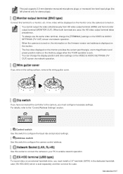
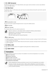
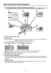
...67 8 ⦇ Control switch: Use this switch to configure the baud rate and protocol settings. ⦈ Address switch: Use this switch to configure the camera control address. ᶆ Network Socket (LAN: RJ-45, PoE) ᶇ EX-HDD terminal (USB type) To record video on an external hard disk... disk case (VA-HDC4000) which is sold separately and then connect the hard disk drive case. ᶈ HDMI Connector The terminal outputs super-fine HD (High Definition) video signal. Use the terminal to the cable bundle. For the detailed connection procedure, refer to the "Basic Connections" section. (...
...67 8 ⦇ Control switch: Use this switch to configure the baud rate and protocol settings. ⦈ Address switch: Use this switch to configure the camera control address. ᶆ Network Socket (LAN: RJ-45, PoE) ᶇ EX-HDD terminal (USB type) To record video on an external hard disk... disk case (VA-HDC4000) which is sold separately and then connect the hard disk drive case. ᶈ HDMI Connector The terminal outputs super-fine HD (High Definition) video signal. Use the terminal to the cable bundle. For the detailed connection procedure, refer to the "Basic Connections" section. (...
VCC-HD5400 Setup and Summary Manual
Page 6
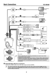
...; AC24 + - ᶄ DC12 System controller Video cable Monitor *2 • Before attempting the following connections, be sure to the HD video output terminal (HDMI). Before attempting to connect each system component, carefully read the instruction manual that comes with it to familiarize yourself... Connect the HDMI cable to turn off all components of your system. • Improper connection may cause smoke or failures. Basic Connections VCC-HD5400 *2 *1 ⦇ HDMI High-definition monitor ⦈ USB HDD *3 LAN *1 ⦉ ⦊ Alarm cable BROWN ALARM_IN1 RED ...
...; AC24 + - ᶄ DC12 System controller Video cable Monitor *2 • Before attempting the following connections, be sure to the HD video output terminal (HDMI). Before attempting to connect each system component, carefully read the instruction manual that comes with it to familiarize yourself... Connect the HDMI cable to turn off all components of your system. • Improper connection may cause smoke or failures. Basic Connections VCC-HD5400 *2 *1 ⦇ HDMI High-definition monitor ⦈ USB HDD *3 LAN *1 ⦉ ⦊ Alarm cable BROWN ALARM_IN1 RED ...
VCC-HD5400 Setup and Summary Manual
Page 15
...: f=6.3 - 63 mm, F number: F1.8 - 2.5 Optical zoom 10x, electronic zoom 16x (up to 160x when used in combination with the optical zoom) Rotational scope Rotation speed Preset position Pan: 360° endless pan Tilt: -20 to +200° Pan: Max. 350°/sec Tilt: Max. 350°/sec (0.1° - 120°/ sec for... 4 (NO/NC), also used for switching between day and night modes 2 (NO/NC, 16V, 150 mA, open collector) Audio input (white: 3.5-mm mini jack) Audio output (black: 3.5-mm mini jack) RS-485 SSP, PELCO-D 2400, 4800, 9600, 19200 1 - 255 (sanyo SSP: 1 to 127) ■ Recording media SD...
...: f=6.3 - 63 mm, F number: F1.8 - 2.5 Optical zoom 10x, electronic zoom 16x (up to 160x when used in combination with the optical zoom) Rotational scope Rotation speed Preset position Pan: 360° endless pan Tilt: -20 to +200° Pan: Max. 350°/sec Tilt: Max. 350°/sec (0.1° - 120°/ sec for... 4 (NO/NC), also used for switching between day and night modes 2 (NO/NC, 16V, 150 mA, open collector) Audio input (white: 3.5-mm mini jack) Audio output (black: 3.5-mm mini jack) RS-485 SSP, PELCO-D 2400, 4800, 9600, 19200 1 - 255 (sanyo SSP: 1 to 127) ■ Recording media SD...

