
Owners Manual
Page 3
...Battery Installation 16 Remote Control Receivers and Operating Range 16 Adjustable Feet 16 Remote Control Code 17 Installation 18 Positioning the Projector 18 Moving the Lens 18 Lens Installation 19 Connecting to a Computer (Digital and Analog RGB) 20 Connecting to ... Warning Indicators 61 Cleaning the Projection Lens 62 Cleaning the Projector Cabinet 62 Appendix 63 Troubleshooting 63 Menu Tree 66 Indicators and Projector Condition 68 Compatible Computer Specifications 70 Technical Specifications 72 Optional Parts 73 PJ Link Notice 74 Configurations of ...
...Battery Installation 16 Remote Control Receivers and Operating Range 16 Adjustable Feet 16 Remote Control Code 17 Installation 18 Positioning the Projector 18 Moving the Lens 18 Lens Installation 19 Connecting to a Computer (Digital and Analog RGB) 20 Connecting to ... Warning Indicators 61 Cleaning the Projection Lens 62 Cleaning the Projector Cabinet 62 Appendix 63 Troubleshooting 63 Menu Tree 66 Indicators and Projector Condition 68 Compatible Computer Specifications 70 Technical Specifications 72 Optional Parts 73 PJ Link Notice 74 Configurations of ...
Owners Manual
Page 19
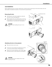
... pressing the Lens release button on the lens with the red dot of the projector. 3 Slowly turn the lens counterclockwise until it out slowly from the projector. Make sure that the lens is fully inserted to the projector by following the instructions below. CAUTION Do not press the lens release button when... lens to the center position by using an optional lens, install the lens by aligning the red dot on the top of the optional lens specifications. Red dots 19 Ask the sales dealer for detailed information of the cabinet, turn the lens clockwise until it stops and pull it clicks....
... pressing the Lens release button on the lens with the red dot of the projector. 3 Slowly turn the lens counterclockwise until it out slowly from the projector. Make sure that the lens is fully inserted to the projector by following the instructions below. CAUTION Do not press the lens release button when... lens to the center position by using an optional lens, install the lens by aligning the red dot on the top of the optional lens specifications. Red dots 19 Ask the sales dealer for detailed information of the cabinet, turn the lens clockwise until it stops and pull it clicks....

Owners Manual
Page 36
PAL/SECAM/NTSC/NTSC4.43/PAL-M/PAL-N If the projector cannot reproduce proper video image, select a specific broadcast signal format from among PAL, SECAM, NTSC, NTSC 4.43, PAL-M, and PAL-N. Move the pointer to the desired system and then ...itself to optimize its performance. When Video System is PAL-M or PAL-N, select the system manually. COMPONENT VIDEO SIGNAL FORMAT If the projector cannot reproduce proper video image, select a specific component video signal format from among 480i, 575i, 480p, 575p, 720p, 1035i, and 1080i. Input Selection Video System Selection 1 ...
PAL/SECAM/NTSC/NTSC4.43/PAL-M/PAL-N If the projector cannot reproduce proper video image, select a specific broadcast signal format from among PAL, SECAM, NTSC, NTSC 4.43, PAL-M, and PAL-N. Move the pointer to the desired system and then ...itself to optimize its performance. When Video System is PAL-M or PAL-N, select the system manually. COMPONENT VIDEO SIGNAL FORMAT If the projector cannot reproduce proper video image, select a specific component video signal format from among 480i, 575i, 480p, 575p, 720p, 1035i, and 1080i. Input Selection Video System Selection 1 ...

Owners Manual
Page 39
Manual PC Adjustment enables you to recall the setting for a specific computer. 1 Press the MENU button to store those signal formats. The projector has 10 independent memory areas to display the On-Screen Menu. Horizontal Use the Point 7 8 buttons to adjust the clamp level. Press the SELECT button ... to show the information of total dots in one horizontal period to display the adjustment dialog box. When the image has dark bars, try this projector.
Manual PC Adjustment enables you to recall the setting for a specific computer. 1 Press the MENU button to store those signal formats. The projector has 10 independent memory areas to display the On-Screen Menu. Horizontal Use the Point 7 8 buttons to adjust the clamp level. Press the SELECT button ... to show the information of total dots in one horizontal period to display the adjustment dialog box. When the image has dark bars, try this projector.

Owners Manual
Page 70
Appendix Compatible Computer Specifications Basically this projector can accept the signal from all computers with the V- and H-Frequency mentioned below and less than 140 MHz of Dot Clock. PC Adjustment is limited ... LC13 MAC 13 480p 575p 575i 480i SVGA 1 SVGA 2 SVGA 3 SVGA 4 SVGA 5 SVGA 6 SVGA 7 SVGA 8 SVGA 9 SVGA 10 SVGA 11 MAC 16 XGA 1 XGA 2 XGA 3 XGA 4 XGA 5 XGA 6 XGA 7 XGA 8 XGA 9 XGA 10 XGA 11 XGA 12 XGA 13 XGA 14 XGA 15 MAC 19 SXGA 1 RESOLUTION 640x480 720x400 640x400 640x480 640x480 640x480 640x480 640x480 640x480 640x480 768x575 768x576 640x480 800x600 800x600 800x600 800x600 800x600...
Appendix Compatible Computer Specifications Basically this projector can accept the signal from all computers with the V- and H-Frequency mentioned below and less than 140 MHz of Dot Clock. PC Adjustment is limited ... LC13 MAC 13 480p 575p 575i 480i SVGA 1 SVGA 2 SVGA 3 SVGA 4 SVGA 5 SVGA 6 SVGA 7 SVGA 8 SVGA 9 SVGA 10 SVGA 11 MAC 16 XGA 1 XGA 2 XGA 3 XGA 4 XGA 5 XGA 6 XGA 7 XGA 8 XGA 9 XGA 10 XGA 11 XGA 12 XGA 13 XGA 14 XGA 15 MAC 19 SXGA 1 RESOLUTION 640x480 720x400 640x400 640x480 640x480 640x480 640x480 640x480 640x480 640x480 768x575 768x576 640x480 800x600 800x600 800x600 800x600 800x600...

Owners Manual
Page 71
... 1 and D-SXGA +1 images may not be selected when Input 1 [RGB (PC digital)] is selected in the Input Menu. ON-SCREEN DISPLAY D-VGA D-480p D-575p D-SVGA D-XGA D-WXGA 1 D-WXGA 2 D-WXGA 3 D-WXGA 4 D-WXGA 5 RESOLUTION 640x480 720x480 768x575 800x600 1024x768 1366x768 1360x768 1376x768 1360x768 1366x768 H-Freq. (kHz) 31.470 31.470 31.250 37... input signal is digital from the DVI terminal, refer to change without notice.. 71 PC Adjust Menu cannot be displayed properly depending on computers • Specifications are subject to the chart below.
... 1 and D-SXGA +1 images may not be selected when Input 1 [RGB (PC digital)] is selected in the Input Menu. ON-SCREEN DISPLAY D-VGA D-480p D-575p D-SVGA D-XGA D-WXGA 1 D-WXGA 2 D-WXGA 3 D-WXGA 4 D-WXGA 5 RESOLUTION 640x480 720x480 768x575 800x600 1024x768 1366x768 1360x768 1376x768 1360x768 1366x768 H-Freq. (kHz) 31.470 31.470 31.250 37... input signal is digital from the DVI terminal, refer to change without notice.. 71 PC Adjust Menu cannot be displayed properly depending on computers • Specifications are subject to the chart below.

Owners Manual
Page 72
Appendix Technical Specifications Mechanical Information Projector Type Dimensions (W x H x D) Net Weight Feet Adjustment Panel Resolution LCD Panel System Panel Resolution Number of Pixels Signal Compatibility Color System High Definition TV Signal Scanning Frequency Optical Information ..., 720p, 1035i, and 1080i H-sync. 15 kHz-100 kHz, V-sync. 50 Hz-100 Hz Adjustable from 30" to 300" (PLC-XT35) 3.9'-32.8' (1.2 m-10.0 m) (PLC-XT35) F=1.7 to 2.1, f=33 to 43 mm with motor zoom and focus (PLC-XT35) 330 W Digital (DVI-D) x 1, Analog (Mini D-sub 15 pin) x 1 BNC Type x 5 (G or Video/Y, B or Cb...
Appendix Technical Specifications Mechanical Information Projector Type Dimensions (W x H x D) Net Weight Feet Adjustment Panel Resolution LCD Panel System Panel Resolution Number of Pixels Signal Compatibility Color System High Definition TV Signal Scanning Frequency Optical Information ..., 720p, 1035i, and 1080i H-sync. 15 kHz-100 kHz, V-sync. 50 Hz-100 Hz Adjustable from 30" to 300" (PLC-XT35) 3.9'-32.8' (1.2 m-10.0 m) (PLC-XT35) F=1.7 to 2.1, f=33 to 43 mm with motor zoom and focus (PLC-XT35) 330 W Digital (DVI-D) x 1, Analog (Mini D-sub 15 pin) x 1 BNC Type x 5 (G or Video/Y, B or Cb...

Owners Manual
Page 73
... Guide AC Power Cord Remote Control and Batteries VGA Cable USB Cable Control Cable Lens Cap (for PLC-XT35) Lens Mount Cover (for PLC-XT35L) PIN Code Label ● The specifications are subject to change without notice. ● LCD panels are optionally available. Optional Parts The parts listed below are manufactured to the sales dealer...
... Guide AC Power Cord Remote Control and Batteries VGA Cable USB Cable Control Cable Lens Cap (for PLC-XT35) Lens Mount Cover (for PLC-XT35L) PIN Code Label ● The specifications are subject to change without notice. ● LCD panels are optionally available. Optional Parts The parts listed below are manufactured to the sales dealer...