Operation Manual
Page 1
SRP - 350 RECEIPT PRINTER Operator's Manual All specifications are subjected to change without notice
SRP - 350 RECEIPT PRINTER Operator's Manual All specifications are subjected to change without notice
Operation Manual
Page 2
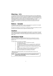
Operation of this manual carefully before you should turn the printer "OFF". INTRODUCTION The SRP-350, SRP-350S, SRP-350P and SRP-350U Roll Printer are easily damaged by DIP switches. Peripheral units drive circuit enables control of the printer are designed to provide reasonable protection against the static electricity. The data buffer allows the unit to radio communications. RS-232(SRP-350), RS-485(SRP-350S), Parallel(SRP-350P), USB(SRP-350U) 4. Notice - You should turn the printer "OFF", before using a bar...
Operation of this manual carefully before you should turn the printer "OFF". INTRODUCTION The SRP-350, SRP-350S, SRP-350P and SRP-350U Roll Printer are easily damaged by DIP switches. Peripheral units drive circuit enables control of the printer are designed to provide reasonable protection against the static electricity. The data buffer allows the unit to radio communications. RS-232(SRP-350), RS-485(SRP-350S), Parallel(SRP-350P), USB(SRP-350U) 4. Notice - You should turn the printer "OFF", before using a bar...
Operation Manual
Page 3
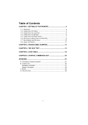
UNPACKING 4 1-2. CONNECTING THE DRAWER 6 1-5. HEXADECIMAL DUMPING 14 CHAPTER 3. ADJUSTMENTS AND SETTINGS 10 1-8. STAR MODE COMMAND SUMMARY 27 B. Table of Contents CHAPTER 1. SETTING UP THE PRINTER 4 1-1. INSTALLING OR REPLACING THE PAPER ROLL 8 1-7. THE SELF TEST 15 CHAPTER 4. CONNECTORS 30 Interface Connector 31 Drawer Connector 34 C. CONNECTING THE CABLES 5 1-3. CONNECTING THE POWER SUPPLY 7 1-6. SPECIFICATION 35 3 CONNECTING THE COMPUTER 6 1-4. CONTROL COMMANDS LIST 24 APPENDIX 27 A. NOTES 34 D. CODE TABLE 16 CHAPTER 5. USING THE PRINTER 11...
UNPACKING 4 1-2. CONNECTING THE DRAWER 6 1-5. HEXADECIMAL DUMPING 14 CHAPTER 3. ADJUSTMENTS AND SETTINGS 10 1-8. STAR MODE COMMAND SUMMARY 27 B. Table of Contents CHAPTER 1. SETTING UP THE PRINTER 4 1-1. INSTALLING OR REPLACING THE PAPER ROLL 8 1-7. THE SELF TEST 15 CHAPTER 4. CONNECTORS 30 Interface Connector 31 Drawer Connector 34 C. CONNECTING THE CABLES 5 1-3. CONNECTING THE POWER SUPPLY 7 1-6. SPECIFICATION 35 3 CONNECTING THE COMPUTER 6 1-4. CONTROL COMMANDS LIST 24 APPENDIX 27 A. NOTES 34 D. CODE TABLE 16 CHAPTER 5. USING THE PRINTER 11...

Operation Manual
Page 6
... the back of the cable connector. 3. Plug the cable connector securely into the drawer kick-out connector on both sides of the printer next to the computer. 1-4. Connecting the Drawer WARNING: Use a drawer that matches the printer specification. Connecting the computer You need an appropriate interface cable. 1. Using an improper drawer may be damaged. CAUTION: Do not connect a telephone line to the drawer kick...
... the back of the cable connector. 3. Plug the cable connector securely into the drawer kick-out connector on both sides of the printer next to the computer. 1-4. Connecting the Drawer WARNING: Use a drawer that matches the printer specification. Connecting the computer You need an appropriate interface cable. 1. Using an improper drawer may be damaged. CAUTION: Do not connect a telephone line to the drawer kick...

Operation Manual
Page 7
... printer's power switch is turned off, and the power supply's power cord is unplugged from the printer, make sure that the power supply is unplugged; Otherwise you may damage the power supply or the printer. Make sure that the flat side of your dealer for assistance. Check the label on the power supply to make sure that of the plug faces down. Notes : To remove the DC cable...
... printer's power switch is turned off, and the power supply's power cord is unplugged from the printer, make sure that the power supply is unplugged; Otherwise you may damage the power supply or the printer. Make sure that the flat side of your dealer for assistance. Check the label on the power supply to make sure that of the plug faces down. Notes : To remove the DC cable...

Operation Manual
Page 8
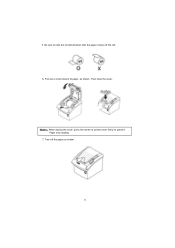
Make sure that have the paper glued to use paper rolls that the printer is not receiving data; Open the paper roll cover by pressing the cover-open the print cover while the printer is one. 4. Remove the used paper roll core if there is operating. 1-6. otherwise, data may damage the printer. 3. Notes : Do not open button. This may be lost. 2. Insert the paper roll as shown. 8 Do not use paper rolls that meet the specifications. Installing or Replacing the Paper Roll Notes : Be sure to the core because the printer cannot detect the paper end correctly. 1.
Make sure that have the paper glued to use paper rolls that the printer is not receiving data; Open the paper roll cover by pressing the cover-open the print cover while the printer is one. 4. Remove the used paper roll core if there is operating. 1-6. otherwise, data may damage the printer. 3. Notes : Do not open button. This may be lost. 2. Insert the paper roll as shown. 8 Do not use paper rolls that meet the specifications. Installing or Replacing the Paper Roll Notes : Be sure to the core because the printer cannot detect the paper end correctly. 1.
Operation Manual
Page 9
5. Then close the cover. Tear off the roll. 6. Notes : When closing the cover, press the center of paper, as shown. 9 Be sure to prevent Paper miss-loading. 7. Pull out a small amount of printer cover firmly to note the correct direction that the paper comes off the paper as shown.
5. Then close the cover. Tear off the roll. 6. Notes : When closing the cover, press the center of paper, as shown. 9 Be sure to prevent Paper miss-loading. 7. Pull out a small amount of printer cover firmly to note the correct direction that the paper comes off the paper as shown.
Operation Manual
Page 10
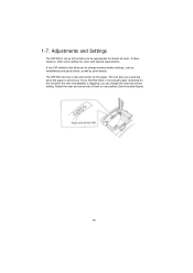
... SRP-350 also has a near end sensor tab at the factory to be appropriate for almost all users. Rotate the near -end sensor for users with special requirements. It does, however, offer some settings for the paper. If you find that allow you a warning when the paper is almost out. 1-7. This can change communication settings, such as handshaking and parity check...
... SRP-350 also has a near end sensor tab at the factory to be appropriate for almost all users. Rotate the near -end sensor for users with special requirements. It does, however, offer some settings for the paper. If you find that allow you a warning when the paper is almost out. 1-7. This can change communication settings, such as handshaking and parity check...

Operation Manual
Page 11
When the light blinks, it indicates the self-test printing standby state or macro execution standby state when the macro execution command is on whenever the printer is used. 11 Press the FEED button once to feed paper continuously. PAPER OUT This light indicates the near end of the paper roll. Panel lights POWER The POWER light is on . Install a new paper roll and the printer will continue printing. Using the Printer Control Panel Button The button can also hold...
When the light blinks, it indicates the self-test printing standby state or macro execution standby state when the macro execution command is on whenever the printer is used. 11 Press the FEED button once to feed paper continuously. PAPER OUT This light indicates the near end of the paper roll. Panel lights POWER The POWER light is on . Install a new paper roll and the printer will continue printing. Using the Printer Control Panel Button The button can also hold...
Operation Manual
Page 12
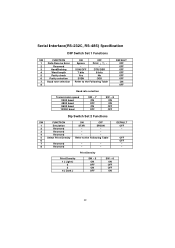
...(RS-232C, RS-485) Specification DIP Switch Set 1 Functions SW FUNCTION ON OFF 1 Data Receive Error Ignore Print ¡ °?¡ ± 2 Reserved - - 3 HandShaking XON/OFF DTR/DSR 4 Word length 7 bits 8 bits 5 Parity check Yes No 6 Parity selection EVEN ODD 7 Baud rate selection Refer to the Following Table - - - - DEFAULT OFF - Print Density Print Density 1 ( Light ) 2 3 4 ( Dark ) SW - 5 ON OFF ON OFF...
...(RS-232C, RS-485) Specification DIP Switch Set 1 Functions SW FUNCTION ON OFF 1 Data Receive Error Ignore Print ¡ °?¡ ± 2 Reserved - - 3 HandShaking XON/OFF DTR/DSR 4 Word length 7 bits 8 bits 5 Parity check Yes No 6 Parity selection EVEN ODD 7 Baud rate selection Refer to the Following Table - - - - DEFAULT OFF - Print Density Print Density 1 ( Light ) 2 3 4 ( Dark ) SW - 5 ON OFF ON OFF...
Operation Manual
Page 14
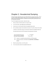
... to help you turn off , open the cover. 2. Turn on the printer and then the hexadecimal mode is off the printer. 6. When the printing finishes, turn on the hexadecimal dump function, the printer prints all commands except DLE EOT and DLE ENQ are disabled. 5. Turn on the printer, while holding down the FEED button. 3. This can be useful in finding software problems. When you find specific commands. Close the cover, then the printer...
... to help you turn off , open the cover. 2. Turn on the printer and then the hexadecimal mode is off the printer. 6. When the printing finishes, turn on the hexadecimal dump function, the printer prints all commands except DLE EOT and DLE ENQ are disabled. 5. Turn on the printer, while holding down the FEED button. 3. This can be useful in finding software problems. When you find specific commands. Close the cover, then the printer...
Operation Manual
Page 15
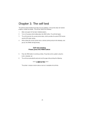
... installed properly. 2. Turn on the power while holding down the FEED button. Chapter 3. Please press the FEED button 5. Press the FEED button to receive data as soon as it completes the self-test. 15 The self-test begins. 3. Self-test printing. The self-test checks the following , and pause (The PAPER LED light blinks). After printing the current printer status, self-test printing will print the following ; 1. The printer prints a pattern using the built-in character set. 6. The self test...
... installed properly. 2. Turn on the power while holding down the FEED button. Chapter 3. Please press the FEED button 5. Press the FEED button to receive data as soon as it completes the self-test. 15 The self-test begins. 3. Self-test printing. The self-test checks the following , and pause (The PAPER LED light blinks). After printing the current printer status, self-test printing will print the following ; 1. The printer prints a pattern using the built-in character set. 6. The self test...
Operation Manual
Page 24
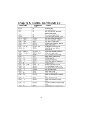
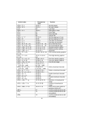
... character set Define user-defined characters Select bit-image mode Turn underline mode on/off Select default line spacing Set line spacing Set peripheral device Cancel user-defined characters Initialize printer Set horizontal tab position Turn emphasized mode on/off Turn double-strike mode on/off Print and feed paper Select page mode Select character fonts Select an international character set Select standard mode Select print direction in page mode Turn 90º clockwise rotation mode on/off Set printing area in page mode 24 Control Commands List Control codes...
... character set Define user-defined characters Select bit-image mode Turn underline mode on/off Select default line spacing Set line spacing Set peripheral device Cancel user-defined characters Initialize printer Set horizontal tab position Turn emphasized mode on/off Turn double-strike mode on/off Print and feed paper Select page mode Select character fonts Select an international character set Select standard mode Select print direction in page mode Turn 90º clockwise rotation mode on/off Set printing area in page mode 24 Control Commands List Control codes...
Operation Manual
Page 25
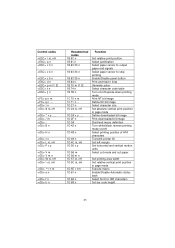
... output paper end signals Select paper sensor to stop printing Enable/Disable panel button Print and feed n lines Generate pulse Select character code table Turn on/off upside-down printing mode Print NT bit image Define NV bit image Select character size Set absolute vertical print position in page mode Define downloaded bit image Print downloaded bit image Start/end macro definition Turn white/black reverse printing mode on/off Select printing position of HRI characters Transmit printer ID Set left margin Set horizontal and vertical motion units...
... output paper end signals Select paper sensor to stop printing Enable/Disable panel button Print and feed n lines Generate pulse Select character code table Turn on/off upside-down printing mode Print NT bit image Define NV bit image Select character size Set absolute vertical print position in page mode Define downloaded bit image Print downloaded bit image Start/end macro definition Turn white/black reverse printing mode on/off Select printing position of HRI characters Transmit printer ID Set left margin Set horizontal and vertical motion units...
Operation Manual
Page 27
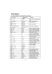
... printing magnified double in character width. Resets the printing magnified in character height. Sets the magnification rate in character height. Resets the printing magnified in character height. Select underlining Select overlining Select highlight printing Cancel highlight printing Inverted printing Cancel inverted printing Select emphasized printing Cancel emphasized printing Set page length in lines Set page length in character width. dk "M" "p" "P" ":" n "W" n "h" n "-" "1" "-:" "_" "1" "_" "4" "5" "E" "F" "C" n "C" n "N" n "O" Hexadecimal codes...
... printing magnified double in character width. Resets the printing magnified in character height. Sets the magnification rate in character height. Resets the printing magnified in character height. Select underlining Select overlining Select highlight printing Cancel highlight printing Inverted printing Cancel inverted printing Select emphasized printing Cancel emphasized printing Set page length in lines Set page length in character width. dk "M" "p" "P" ":" n "W" n "h" n "-" "1" "-:" "_" "1" "_" "4" "5" "E" "F" "C" n "C" n "N" n "O" Hexadecimal codes...
Operation Manual
Page 28
... margin Line Feed Feed paper n lines Form Feed Horizontal tab Vertical tab Set line spacing to 4 mm Set line spacing to 3 mm One time n/4 mm feed One time n/8 mm feed Set vertical tab stops Set horizontal tab stops Absolute position setting Relative position setting Alignment Print normal density graphics 1B 4C n1 n2 m1 m2 1B 6B n 00 d1 1B 58 n1 n2 1B 1C 70 n m 1B 26 31 31 n m1 m2 ... Control...
... margin Line Feed Feed paper n lines Form Feed Horizontal tab Vertical tab Set line spacing to 4 mm Set line spacing to 3 mm One time n/4 mm feed One time n/8 mm feed Set vertical tab stops Set horizontal tab stops Absolute position setting Relative position setting Alignment Print normal density graphics 1B 4C n1 n2 m1 m2 1B 6B n 00 d1 1B 58 n1 n2 1B 1C 70 n m 1B 26 31 31 n m1 m2 ... Control...
Operation Manual
Page 29
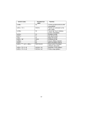
Cancel last line & initialize printer immediately Deselect printer Set select mode Beep the buzzer Initialize printer Inquiry (Status inquiry) Near end status inquiry Reset printer hardware (Perform test print) Registers a logo pattern Prints a logo pattern 29 "8" n1 n2 "9" n1 n2 Hexadecimal codes 1A 1B 64 n 18 13 11 1E 1B 40 05 04 1B 3F 0A 00 1B 38 n1 n2 1B 39 n1 n2 Function Control peripheral device #2 immediately Partial-cut command to the auto cutter. Control codes "d" n "@" "?"
Cancel last line & initialize printer immediately Deselect printer Set select mode Beep the buzzer Initialize printer Inquiry (Status inquiry) Near end status inquiry Reset printer hardware (Perform test print) Registers a logo pattern Prints a logo pattern 29 "8" n1 n2 "9" n1 n2 Hexadecimal codes 1A 1B 64 n 18 13 11 1E 1B 40 05 04 1B 3F 0A 00 1B 38 n1 n2 1B 39 n1 n2 Function Control peripheral device #2 immediately Partial-cut command to the auto cutter. Control codes "d" n "@" "?"
Operation Manual
Page 31
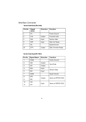
Interface Connector Serial Interface(RS-232) Pin No. 1 2 3 6 7 20 Signal name FG TxD RxD DSR SG DTR Direction Function Output Input Input Output Frame Ground Transmit Data Receive Data Data Set Ready Signal Ground Data Terminal Ready Serial Interface(RS-485) Pin No. Output Input Function Frame Ground Send Data Receive Data Signal Ground Same as DTR(RS-232) Same as DSR(RS-232) 31 Signal Name 1 FGND 2 SD2 3 SD1 4 RD2 5 RD1 7 SGND 8 DR2 9 DR1 10 CS2 11 CS1 Direction Output Output Input Input -
Interface Connector Serial Interface(RS-232) Pin No. 1 2 3 6 7 20 Signal name FG TxD RxD DSR SG DTR Direction Function Output Input Input Output Frame Ground Transmit Data Receive Data Data Set Ready Signal Ground Data Terminal Ready Serial Interface(RS-485) Pin No. Output Input Function Frame Ground Send Data Receive Data Signal Ground Same as DTR(RS-232) Same as DSR(RS-232) 31 Signal Name 1 FGND 2 SD2 3 SD1 4 RD2 5 RD1 7 SGND 8 DR2 9 DR1 10 CS2 11 CS1 Direction Output Output Input Input -
Operation Manual
Page 34
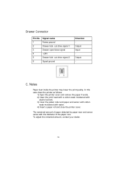
... Paper dust inside the printer may lower the print quality. out drive signal 2 Signal ground Direction Output Input Output - Drawer Connector Pin No. 1 2 3 4 5 6 Signal name Frame ground Drawer kick- The remained amount of the paper core. In this case clean the printer as follows. 1) Open the printer cover and remove the paper if exists. 2) Clean the print head with a cotton swab moistened with alcohol solvent. 3) Clean the platen roller and paper...
... Paper dust inside the printer may lower the print quality. out drive signal 2 Signal ground Direction Output Input Output - Drawer Connector Pin No. 1 2 3 4 5 6 Signal name Frame ground Drawer kick- The remained amount of the paper core. In this case clean the printer as follows. 1) Open the printer cover and remove the paper if exists. 2) Clean the print head with a cotton swab moistened with alcohol solvent. 3) Clean the platen roller and paper...

Operation Manual
Page 35
... * MCBF * Humidity Mechanism Head Auto Cutter Mechanism 30 ~ 80 % RH (Operating) 10 ~ 90 % RH (Storage) ; Specification Printing method Thermal line printing Dot density 180 X 180 dpi (7dots/mm) Printing width 72.192 +0.2mm or -0.2mm Paper width Characters per line (default) 79 ~ 80 mm 42 (Font A) 56 (Font B) Printing speed 35.5 lines/sec(1/6" Feed) 150 mm/sec Receive Buffer Size 4K Bytes NOTE : Printing speed may vary...
... * MCBF * Humidity Mechanism Head Auto Cutter Mechanism 30 ~ 80 % RH (Operating) 10 ~ 90 % RH (Storage) ; Specification Printing method Thermal line printing Dot density 180 X 180 dpi (7dots/mm) Printing width 72.192 +0.2mm or -0.2mm Paper width Characters per line (default) 79 ~ 80 mm 42 (Font A) 56 (Font B) Printing speed 35.5 lines/sec(1/6" Feed) 150 mm/sec Receive Buffer Size 4K Bytes NOTE : Printing speed may vary...


