
User Manual
Page 3
... z Product has been improperly used or handled by the manufacturer of this warranty does not cover any accident, neglect, alteration, or misuse of Samsung Techwin Co., Ltd. are protected by connecting a power supply with the warranty. The product warranty period is for fair use within the scope ...of God" (fire, flood, tsunami, natural disaster, etc.) z To replace expendable components: HDD, Fan, etc. (The warranty for the HDD and Fan is not responsible for the NVR network DVR products. z Product has been damaged due to install and/or operate the...
... z Product has been improperly used or handled by the manufacturer of this warranty does not cover any accident, neglect, alteration, or misuse of Samsung Techwin Co., Ltd. are protected by connecting a power supply with the warranty. The product warranty period is for fair use within the scope ...of God" (fire, flood, tsunami, natural disaster, etc.) z To replace expendable components: HDD, Fan, etc. (The warranty for the HDD and Fan is not responsible for the NVR network DVR products. z Product has been damaged due to install and/or operate the...

User Manual
Page 5
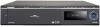
... 3.2.1. Product Contents 9 Chapter 2. Front Panel ...10 2.2. Installation 18 3.1. Sensor...23 3.1.6. Installing and Connecting Product 18 3.1.1. Connecting and Changing Settings 28 3 System Page...17 Chapter 3. Internal HDD ...19 3.1.4. Overview 6 1.1. Back Panel...12 2.3. Config Page ...14 2.3.4. Adding an IP Address 26 3.2.3. Table of Contents Preface 1 Product Warranty and Limited Liability 1 Table of Contents...
... 3.2.1. Product Contents 9 Chapter 2. Front Panel ...10 2.2. Installation 18 3.1. Sensor...23 3.1.6. Installing and Connecting Product 18 3.1.1. Connecting and Changing Settings 28 3 System Page...17 Chapter 3. Internal HDD ...19 3.1.4. Overview 6 1.1. Back Panel...12 2.3. Config Page ...14 2.3.4. Adding an IP Address 26 3.2.3. Table of Contents Preface 1 Product Warranty and Limited Liability 1 Table of Contents...
User Manual
Page 6
...49 4.6.5. Upgrade ...67 4.7.2. Relay Off ...79 5.1.4. System Update 79 5.1.5. Login ...32 4.4. PTZ Control...34 4.4.4. Status ...43 4.6.2. HDD Setup ...53 4.6.6. System ...66 4.7.1. Checking Firmware Version 78 5.1.2. OSD Control...35 4.5. Event Setup ...45 4.6.4. Time Setup ...64 ...4.6. System Log ...69 4.7.3. Backup ...73 Chapter 5. Turning On/Off Beep 78 5.1.3. Chapter 4. User Setup ...72 4.7.4. HDD Check ...81 5.1.7. Video Control ...34 4.4.3. Time Search ...37 4.5.2. System ...78 5.1.1. Network Setup 59 4.6.7. System Requirements ...
...49 4.6.5. Upgrade ...67 4.7.2. Relay Off ...79 5.1.4. System Update 79 5.1.5. Login ...32 4.4. PTZ Control...34 4.4.4. Status ...43 4.6.2. HDD Setup ...53 4.6.6. System ...66 4.7.1. Checking Firmware Version 78 5.1.2. OSD Control...35 4.5. Event Setup ...45 4.6.4. Time Setup ...64 ...4.6. System Log ...69 4.7.3. Backup ...73 Chapter 5. Turning On/Off Beep 78 5.1.3. Chapter 4. User Setup ...72 4.7.4. HDD Check ...81 5.1.7. Video Control ...34 4.4.3. Time Search ...37 4.5.2. System ...78 5.1.1. Network Setup 59 4.6.7. System Requirements ...

User Manual
Page 7
Source Ethernet Port Setup 86 5.2.3. Removing HDDs 91 5.5. Formatting a Single External HDD 93 5.5.4. Formatting All External HDDs 95 5.5.5. Formatting a Single Internal HDD 92 5.5.2. 5.2. Formatting All Internal HDDs 93 5.5.3. Storage Ethernet Port Setup 87 5.3. Formatting HDDs 92 5.5.1. Monitor Ethernet Port Setup 83 5.2.2. HDD Mode Setup 88 5.4. Formatting All HDDs 96 Troubleshooting 97 Product Specifications 99 Product Dimensions 101 5 Network Setup 83 5.2.1.
Source Ethernet Port Setup 86 5.2.3. Removing HDDs 91 5.5. Formatting a Single External HDD 93 5.5.4. Formatting All External HDDs 95 5.5.5. Formatting a Single Internal HDD 92 5.5.2. 5.2. Formatting All Internal HDDs 93 5.5.3. Storage Ethernet Port Setup 87 5.3. Formatting HDDs 92 5.5.1. Monitor Ethernet Port Setup 83 5.2.2. HDD Mode Setup 88 5.4. Formatting All HDDs 96 Troubleshooting 97 Product Specifications 99 Product Dimensions 101 5 Network Setup 83 5.2.1.

User Manual
Page 8
Overview This digital video recorder plus disk player features HDD storage and playback capabilities for user safety; Safety Precautions Warning The following information or instruction is a self-sufficient video recorder as well as ideal for ...
Overview This digital video recorder plus disk player features HDD storage and playback capabilities for user safety; Safety Precautions Warning The following information or instruction is a self-sufficient video recorder as well as ideal for ...

User Manual
Page 11
1.2. Product Contents The contents of this product are as shown below. Power Cord Rack Mount and Fixture Key Screws HDD Fixture Screws User's Manual Quick Reference Guide NET-I Viewer/User's Manual CD Cross Cable HDD Tray (4EA) 9
1.2. Product Contents The contents of this product are as shown below. Power Cord Rack Mount and Fixture Key Screws HDD Fixture Screws User's Manual Quick Reference Guide NET-I Viewer/User's Manual CD Cross Cable HDD Tray (4EA) 9

User Manual
Page 12
... HDD2 9 EXTERNAL HDD3 Function Turning the key completely engages the lock, so the buttons on the front panel cannot be accessed and the HDD bay door cannot be mounted. Mounts hard disks for storing recorded video. A red indicator means that Internal HDD4 is not functioning properly. ... is installed and functioning normally. A blue indicator means that Internal HDD1 is connected to the rear eSATA Port1 and functioning normally. Mounted HDDs are referred to four hard disks can be opened. A red indicator means that Internal HDD4 is not functioning properly. A red indicator ...
... HDD2 9 EXTERNAL HDD3 Function Turning the key completely engages the lock, so the buttons on the front panel cannot be accessed and the HDD bay door cannot be mounted. Mounts hard disks for storing recorded video. A red indicator means that Internal HDD4 is not functioning properly. ... is installed and functioning normally. A blue indicator means that Internal HDD1 is connected to the rear eSATA Port1 and functioning normally. Mounted HDDs are referred to four hard disks can be opened. A red indicator means that Internal HDD4 is not functioning properly. A red indicator ...

User Manual
Page 13
... Button Function A blue indicator means that the product is connected to change the system configuration with the adjacent buttons. A blue indicator means that an external HDD is running in Input Group has occurred. A blue indicator means that a network cable is properly connected to the Source Ethernet Port, and data communication is...
... Button Function A blue indicator means that the product is connected to change the system configuration with the adjacent buttons. A blue indicator means that an external HDD is running in Input Group has occurred. A blue indicator means that a network cable is properly connected to the Source Ethernet Port, and data communication is...
User Manual
Page 14
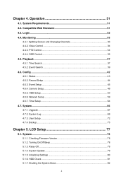
... Attached Storage) within the same network. Used to connect the product power cable. Used to connect an external HDD. Used to upgrade the firmware version of the product. Used to connect an external HDD. Turns on or off the product. Back Panel No. This fan cools the power supply. Used to connect... an external HDD. Used to connect a sensor or alarm. Unused terminal. 12 A network port that is used to ground the frame to the video camera. A terminal that connects...
... Attached Storage) within the same network. Used to connect the product power cable. Used to connect an external HDD. Used to upgrade the firmware version of the product. Used to connect an external HDD. Turns on or off the product. Back Panel No. This fan cools the power supply. Used to connect... an external HDD. Used to connect a sensor or alarm. Unused terminal. 12 A network port that is used to ground the frame to the video camera. A terminal that connects...
User Manual
Page 17
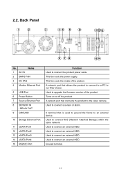
Static IP 0.0.0.0 4000 MPEG Off High D1 10 Default Setting On Off 180 Normal Nas1 Disable 0.0.0.0 - ™ Camera Setup Main Menu Channel List Channel Setup ™ HDD Setup Main Menu HDD AutoDeletion RAID Mode NAS Configuration Sub Menu Open Channel List Select Channel Disable/Enable Channel Name Model Connection Type IP Connection Port ID Password Picture Type ATC Mode Video Quality Video Resolution Video Framerate Sub Menu Repeat Recording Mode Duration Nas Port Use Name Default Folder IP ID Password 15 Default Setting Ch1 ~ Ch16 Ch01 Disable Ch01, Ch02, Ch03, ...
Static IP 0.0.0.0 4000 MPEG Off High D1 10 Default Setting On Off 180 Normal Nas1 Disable 0.0.0.0 - ™ Camera Setup Main Menu Channel List Channel Setup ™ HDD Setup Main Menu HDD AutoDeletion RAID Mode NAS Configuration Sub Menu Open Channel List Select Channel Disable/Enable Channel Name Model Connection Type IP Connection Port ID Password Picture Type ATC Mode Video Quality Video Resolution Video Framerate Sub Menu Repeat Recording Mode Duration Nas Port Use Name Default Folder IP ID Password 15 Default Setting Ch1 ~ Ch16 Ch01 Disable Ch01, Ch02, Ch03, ...

User Manual
Page 21
. 3.1.3. Internal HDD Open the HDD Bay as shown below to add, remove, or replace an internal HDD. ① Press PUSH to open the Locking Door. ② Turn Key Lock counterclockwise to unlock. 19
. 3.1.3. Internal HDD Open the HDD Bay as shown below to add, remove, or replace an internal HDD. ① Press PUSH to open the Locking Door. ② Turn Key Lock counterclockwise to unlock. 19

User Manual
Page 22
③ Open the HDD Door. ④ While pressing the HDD Hook down, pull on the handle to pull out the SATA Bracket. ⑤ Unscrew the fixture screws on the SATA Bracket before removing the HDD; fasten the screws securely after you insert the HDD in the SATA Bracket. 20
③ Open the HDD Door. ④ While pressing the HDD Hook down, pull on the handle to pull out the SATA Bracket. ⑤ Unscrew the fixture screws on the SATA Bracket before removing the HDD; fasten the screws securely after you insert the HDD in the SATA Bracket. 20

User Manual
Page 23
⑥ Make sure that the SATA Bracket is pushed back all the way in the HDD Bay, and close the HDD Door. ⑦ Turn Key Lock clockwise to lock. ⑧ Close the Locking Door. 21
⑥ Make sure that the SATA Bracket is pushed back all the way in the HDD Bay, and close the HDD Door. ⑦ Turn Key Lock clockwise to lock. ⑧ Close the Locking Door. 21

User Manual
Page 24
... Lock clockwise completely. 3.1.4. Note For a list of storage capacity by utilizing the internal HDDs and eSATA ports. (Based on the rear panel. Note that the new HDD is in the front LCD. Internal HDD [2] Added successfully! Upon completing the formatting process, the message above is displayed in the... to the device connected to "5.4. Caution To lock the HDD door, please make sure to use. four eSATA ports are located on 1TB data capacity per HDD.) An external eSATA HDD can be connected to Caution Do Not remove an HDD while the product is in operation. ⑨ When adding...
... Lock clockwise completely. 3.1.4. Note For a list of storage capacity by utilizing the internal HDDs and eSATA ports. (Based on the rear panel. Note that the new HDD is in the front LCD. Internal HDD [2] Added successfully! Upon completing the formatting process, the message above is displayed in the... to the device connected to "5.4. Caution To lock the HDD door, please make sure to use. four eSATA ports are located on 1TB data capacity per HDD.) An external eSATA HDD can be connected to Caution Do Not remove an HDD while the product is in operation. ⑨ When adding...

User Manual
Page 25
... with the product. ƒ For a list of Input Circuits 2 Spec Input Types Supported Sensor Types N.C , N.O Dry Contact sensors. Connect the external HDD (also turned off . 2. Turn on the product. ƒ The eSATA cable is not included with an eSATA interface cable. 3. As such, it...Output Current 150V Typical DC 12mA Please refer to the diagram on the external HDD. 4. However, this may connect an external HDD while the product is recommended that you connect any external HDD by following are specifications and operating conditions for sensor input. Sensor The following ...
... with the product. ƒ For a list of Input Circuits 2 Spec Input Types Supported Sensor Types N.C , N.O Dry Contact sensors. Connect the external HDD (also turned off . 2. Turn on the product. ƒ The eSATA cable is not included with an eSATA interface cable. 3. As such, it...Output Current 150V Typical DC 12mA Please refer to the diagram on the external HDD. 4. However, this may connect an external HDD while the product is recommended that you connect any external HDD by following are specifications and operating conditions for sensor input. Sensor The following ...

User Manual
Page 45
... for the entire channels will be added for the channel are being recorded and saved in the bottom. 4.6.1. Details will be listed in the product's HDD. ƒ "Record" uses data from the camera are displayed. In the meantime, the channel information will be provided in the upper area while the statistics...
... for the entire channels will be added for the channel are being recorded and saved in the bottom. 4.6.1. Details will be listed in the product's HDD. ƒ "Record" uses data from the camera are displayed. In the meantime, the channel information will be provided in the upper area while the statistics...

User Manual
Page 46
..."Setup fail : bitrate exceeds" or "Setup fail : framerate exceeds" (see the figure below), you cannot add a camera any more. 4.6.5. HDD Setup" 4.6.2. Record Setup Select a channel on the current free storage space of all connected data storage units. Total Recordable Time displays a total ...recordable time of the product. If the HDD becomes full during the Repeat Recording mode, the Current Recordable Time menu displays Repeat Recording. Record Status displays remaining recordable ...
..."Setup fail : bitrate exceeds" or "Setup fail : framerate exceeds" (see the figure below), you cannot add a camera any more. 4.6.5. HDD Setup" 4.6.2. Record Setup Select a channel on the current free storage space of all connected data storage units. Total Recordable Time displays a total ...recordable time of the product. If the HDD becomes full during the Repeat Recording mode, the Current Recordable Time menu displays Repeat Recording. Record Status displays remaining recordable ...

User Manual
Page 55
Caution ƒ If you see a message of "Setup fail : bitrate exceeds" or "Setup fail : framerate exceeds" (see the figure below), you can configure the storage devices connected to the system. ™ HDD 53 HDD Setup From this page, you cannot add a camera any more. 4.6.5.
Caution ƒ If you see a message of "Setup fail : bitrate exceeds" or "Setup fail : framerate exceeds" (see the figure below), you can configure the storage devices connected to the system. ™ HDD 53 HDD Setup From this page, you cannot add a camera any more. 4.6.5.

User Manual
Page 56
...On, and the system will automatically delete older data in the list. click it only deletes the entire video data of connected HDDs, click . Formatting HDD is being formatted, an HDD is in the disk checking process, and a new RAID mode is in progress, the front LCD displays the following message. ...Selecting a NAS and then clicking does not format the entire NAS; Note New Repeated Recording setting is in Progress... RAID-configured internal HDDs are listed. While formatting is applied only if you can be used to make room for new video when no free space remains on ...
...On, and the system will automatically delete older data in the list. click it only deletes the entire video data of connected HDDs, click . Formatting HDD is being formatted, an HDD is in the disk checking process, and a new RAID mode is in progress, the front LCD displays the following message. ...Selecting a NAS and then clicking does not format the entire NAS; Note New Repeated Recording setting is in Progress... RAID-configured internal HDDs are listed. While formatting is applied only if you can be used to make room for new video when no free space remains on ...

User Manual
Page 57
..., appears on the right. Preparing RAID1 is in Progress... Displays the current RAID status of the system along with the information of RAID-configured HDDs. 55 Build RAID1: 48.8% Finish: 37.6min RAID1 Setup [DONE] Unbuilding RAID is in Progress... Note If you activate Auto Deletion for ...the first time, HDD data older than specified will be deleted automatically and it may take a while until the Auto Deletion mode gets started. ™ RAID Mode In...
..., appears on the right. Preparing RAID1 is in Progress... Displays the current RAID status of the system along with the information of RAID-configured HDDs. 55 Build RAID1: 48.8% Finish: 37.6min RAID1 Setup [DONE] Unbuilding RAID is in Progress... Note If you activate Auto Deletion for ...the first time, HDD data older than specified will be deleted automatically and it may take a while until the Auto Deletion mode gets started. ™ RAID Mode In...