User Manual
Page 1
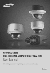
Network Camera SNB-5000/SND-5080/SND-5080F/SNV-5080 User Manual Before installing and operating this product, please read this manual thoroughly. English
Network Camera SNB-5000/SND-5080/SND-5080F/SNV-5080 User Manual Before installing and operating this product, please read this manual thoroughly. English
User Manual
Page 7
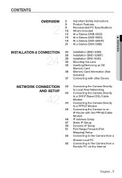
... PC Specifications 10 What's Included 12 At a Glance (SNB-5000) 15 At a Glance (SND-5080) 18 At a Glance (SND-5080F) 21 At a Glance (SNV-5080) INSTALLATION & CONNECTION 24 24 Installation (SND-5080) 26 Installation (SND-5080F) 28 Installation (SNV-5080) 32 Mounting the Lens 33 Inserting/Removing an SD Memory Card 36 Memory Card Information (Not...
... PC Specifications 10 What's Included 12 At a Glance (SNB-5000) 15 At a Glance (SND-5080) 18 At a Glance (SND-5080F) 21 At a Glance (SNV-5080) INSTALLATION & CONNECTION 24 24 Installation (SND-5080) 26 Installation (SND-5080F) 28 Installation (SNV-5080) 32 Mounting the Lens 33 Inserting/Removing an SD Memory Card 36 Memory Card Information (Not...
User Manual
Page 10
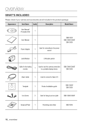
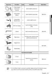
...the product package. Appearance Item Name Quantity Description Model Name User Manual/ IP Installer DVD 1 User Manual 1 SNB-5000 SND-5080/5080F SNV-5080 Power Adapter 1 Used for connecting to the power source Jack Modular 1 LAN cable gender Cable for the testing monitor 1... Used to test the camera connection to a portable display device SND-5080/5080F SNV-5080 Alarm Cable 1 Used to connect to Alarm I/O Template 1 Product installation guide SND-5080F SNV-5080 Iron Screw 3 Used for fixing to an iron plate SND-5080/5080F Dustproof Plate 1 Preventing dust inflow...
...the product package. Appearance Item Name Quantity Description Model Name User Manual/ IP Installer DVD 1 User Manual 1 SNB-5000 SND-5080/5080F SNV-5080 Power Adapter 1 Used for connecting to the power source Jack Modular 1 LAN cable gender Cable for the testing monitor 1... Used to test the camera connection to a portable display device SND-5080/5080F SNV-5080 Alarm Cable 1 Used to connect to Alarm I/O Template 1 Product installation guide SND-5080F SNV-5080 Iron Screw 3 Used for fixing to an iron plate SND-5080/5080F Dustproof Plate 1 Preventing dust inflow...
User Manual
Page 11
... 2 Used to install the mount ASSY-Screw Tapping 4 Used for installation on the wall or ceiling L Wrench 1 Used to remove/fix the dome cover SNV-5080 Plastic Anchor 4 For fixing a screw, Inserted in a hole (reinforced anchoring force) Tapping Screw Bracket Safety Lens Options (not included) CS Lens C Lens Optional lens to...
... 2 Used to install the mount ASSY-Screw Tapping 4 Used for installation on the wall or ceiling L Wrench 1 Used to remove/fix the dome cover SNV-5080 Plastic Anchor 4 For fixing a screw, Inserted in a hole (reinforced anchoring force) Tapping Screw Bracket Safety Lens Options (not included) CS Lens C Lens Optional lens to...
User Manual
Page 15
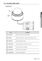
English _15 Used to the monitor. Video signal output port connected to connect a PoE or LAN cable. Main unit includes the lens, switch board, PCB boards and screws. Used to connect to plug the power cable. Used to a microphone. Used to connect to speakers. AT A GLANCE (SND-5080) Appearance M OVERVIEW Item Dome Cover Main unit Power Port Video Out Port Network Port Audio In Jack Audio Out Jack Description Dome cover for the lens and unit protection.
English _15 Used to the monitor. Video signal output port connected to connect a PoE or LAN cable. Main unit includes the lens, switch board, PCB boards and screws. Used to connect to plug the power cable. Used to a microphone. Used to connect to speakers. AT A GLANCE (SND-5080) Appearance M OVERVIEW Item Dome Cover Main unit Power Port Video Out Port Network Port Audio In Jack Audio Out Jack Description Dome cover for the lens and unit protection.
User Manual
Page 18
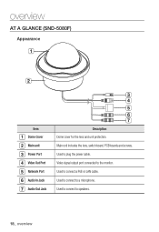
overview AT A GLANCE (SND-5080F) Appearance Item Dome Cover Main unit Power Port Video Out Port Network Port Audio In Jack 7 Audio Out Jack Description Dome cover for the lens and unit protection. Used to connect to plug the power cable. Used to speakers. 18_ overview Used to a microphone. Used to connect to connect a PoE or LAN cable. Main unit includes the lens, switch board, PCB boards and screws. Video signal output port connected to the monitor.
overview AT A GLANCE (SND-5080F) Appearance Item Dome Cover Main unit Power Port Video Out Port Network Port Audio In Jack 7 Audio Out Jack Description Dome cover for the lens and unit protection. Used to connect to plug the power cable. Used to speakers. 18_ overview Used to a microphone. Used to connect to connect a PoE or LAN cable. Main unit includes the lens, switch board, PCB boards and screws. Video signal output port connected to the monitor.
User Manual
Page 24
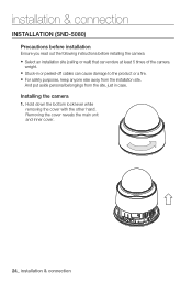
... away from the site, just in or peeled-off cables can endure at least 5 times of the camera weight. Installing the camera 1. installation & connection INSTALLATION (SND-5080) Precautions before installation Ensure you read out the following instructions before installing the camera: y Select an installation site (ceiling or wall) that can cause damage...
... away from the site, just in or peeled-off cables can endure at least 5 times of the camera weight. Installing the camera 1. installation & connection INSTALLATION (SND-5080) Precautions before installation Ensure you read out the following instructions before installing the camera: y Select an installation site (ceiling or wall) that can cause damage...
User Manual
Page 26
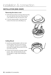
installation & connection INSTALLATION (SND-5080F) Removing the dome cover 1. Use the provided template to drill one hole for the camera, and one for the screw (5 mm in diameter, at ...
installation & connection INSTALLATION (SND-5080F) Removing the dome cover 1. Use the provided template to drill one hole for the camera, and one for the screw (5 mm in diameter, at ...
User Manual
Page 31
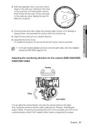
...is fixed on the ceiling. For panning, the panning limit is 220° for the clockwise, and 120° for the camera (SND-5080/SND5080F/SNV-5080) Panning Tilting Lens rotation You can adjust the camera direction only when the camera is referred to your desired direction. 6. Fix the ...anchors (HUD 5) fully into the holes. Assemble the Dome Cover. Connect power and video cables and arrange cable running not to the installation instructions of SND-5080F. (pages 26~27) Adjusting the monitoring direction for the counterclockwise, a total of 340° enabled; English _31 M For the ...
...is fixed on the ceiling. For panning, the panning limit is 220° for the clockwise, and 120° for the camera (SND-5080/SND5080F/SNV-5080) Panning Tilting Lens rotation You can adjust the camera direction only when the camera is referred to your desired direction. 6. Fix the ...anchors (HUD 5) fully into the holes. Assemble the Dome Cover. Connect power and video cables and arrange cable running not to the installation instructions of SND-5080F. (pages 26~27) Adjusting the monitoring direction for the counterclockwise, a total of 340° enabled; English _31 M For the ...
User Manual
Page 38
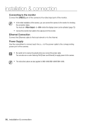
... can be activated. (page 72) Connect the monitor test cable to the output port of the camera. You can connect the camera to SND-5080/SND-5080F/SNV-5080. 38_ installation & connection M The instructions above are also applied to the monitor for checking the connection status. installation & connection Connecting to the monitor...
... can be activated. (page 72) Connect the monitor test cable to the output port of the camera. You can connect the camera to SND-5080/SND-5080F/SNV-5080. 38_ installation & connection M The instructions above are also applied to the monitor for checking the connection status. installation & connection Connecting to the monitor...
User Manual
Page 41
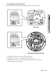
M INSTALLATION & CONNECTION Connecting to the I/O port box Connect the Alarm I/O signal to the corresponding port of the rear port box. 1 2 3 4 5 1 : ALARM IN 4 : 2 : ALARM OUT 5 : GND 3 : ALARM COM SD CARD AUDIO OUT AUDIO IN SD SYSTEM POWER VIDEO RESET 1 2 3 4 5 NETWORK 1 : ALARM IN 4 : 2 : ALARM OUT 5 : GND ACT 3 : ALARM COM LINK GND AC 24V DC 12V 5 4 3 2 1 1 : ALARM IN 4 : 2 : ALARM OUT 5 : GND 3 : ALARM COM y ALARM IN : Used to connect the alarm output signal. y ALARM COM : Common port where the alarm output signal is connected. y GND : Used for earth-grounding. ...
M INSTALLATION & CONNECTION Connecting to the I/O port box Connect the Alarm I/O signal to the corresponding port of the rear port box. 1 2 3 4 5 1 : ALARM IN 4 : 2 : ALARM OUT 5 : GND 3 : ALARM COM SD CARD AUDIO OUT AUDIO IN SD SYSTEM POWER VIDEO RESET 1 2 3 4 5 NETWORK 1 : ALARM IN 4 : 2 : ALARM OUT 5 : GND ACT 3 : ALARM COM LINK GND AC 24V DC 12V 5 4 3 2 1 1 : ALARM IN 4 : 2 : ALARM OUT 5 : GND 3 : ALARM COM y ALARM IN : Used to connect the alarm output signal. y ALARM COM : Common port where the alarm output signal is connected. y GND : Used for earth-grounding. ...

User Manual
Page 88
appendix Items SNB-5000 SND-5080/F SNV-5080 Focal Length - 2.8~10mm Zoom ratio - Lens Drive Type Manual / DC x3.6 F1.2 28.8˚(H) x 21.6˚(V) 94.6˚(H) x 68.4˚(V) AI(DC) Mount Type CS/C ...
appendix Items SNB-5000 SND-5080/F SNV-5080 Focal Length - 2.8~10mm Zoom ratio - Lens Drive Type Manual / DC x3.6 F1.2 28.8˚(H) x 21.6˚(V) 94.6˚(H) x 68.4˚(V) AI(DC) Mount Type CS/C ...

