
User Manual (user Manual) (ver.1.0) (English)
Page 2
... this equipment may be connected to the grounding system of U.S. REFER SERVICING TO QUALIFIED SERVICE PERSONNEL. This symbol alerts you that unauthorized recording of copyrighted TV programs is dangerous to make any unauthorized changes or modifications to this appliance to the wide slot, and fully insert the plug. Caution: To prevent...
... this equipment may be connected to the grounding system of U.S. REFER SERVICING TO QUALIFIED SERVICE PERSONNEL. This symbol alerts you that unauthorized recording of copyrighted TV programs is dangerous to make any unauthorized changes or modifications to this appliance to the wide slot, and fully insert the plug. Caution: To prevent...

User Manual (user Manual) (ver.1.0) (English)
Page 3
... and operating instructions before cleaning. Use a damp cloth; Move the TV and cart with the TV. Do not place it from overheating. If you a product that you for choosing Samsung! Your new Samsung Projection TV represents the latest in its class. Do not block these safety precautions...cart, stand, tripod, bracket, or table recommended by the manufacturer. Thank You for Choosing Samsung Thank you 've followed the manufacturer's instructions for mounting. • Operate your TV receiver only from the type of power source indicated on the marking label. Important Safety ...
... and operating instructions before cleaning. Use a damp cloth; Move the TV and cart with the TV. Do not place it from overheating. If you a product that you for choosing Samsung! Your new Samsung Projection TV represents the latest in its class. Do not block these safety precautions...cart, stand, tripod, bracket, or table recommended by the manufacturer. Thank You for Choosing Samsung Thank you 've followed the manufacturer's instructions for mounting. • Operate your TV receiver only from the type of power source indicated on the marking label. Important Safety ...

User Manual (user Manual) (ver.1.0) (English)
Page 4
...connection to grounding electrodes, and requirements for long periods of overhead power lines or other controls may result in additional damage to the TV, be fatal. • Do not overload the wall outlet or extension cords. NATIONAL ELECTRICAL CODE POWER SERVICE GROUNDING ELECTRODE SYSTEM ...operating condition. Operation is in damage and will prevent damage to the unit due to provide some protection against them. if the TV does not operate normally by the operating instructions. Refer all servicing to normal. • When replacement parts are covered by following...
...connection to grounding electrodes, and requirements for long periods of overhead power lines or other controls may result in additional damage to the TV, be fatal. • Do not overload the wall outlet or extension cords. NATIONAL ELECTRICAL CODE POWER SERVICE GROUNDING ELECTRODE SYSTEM ...operating condition. Operation is in damage and will prevent damage to the unit due to provide some protection against them. if the TV does not operate normally by the operating instructions. Refer all servicing to normal. • When replacement parts are covered by following...

User Manual (user Manual) (ver.1.0) (English)
Page 6
... Box that Descrambles All Channels 2.3 Connecting to a Cable Box that Descrambles some Channels 2.3 Connecting a VCR 2.5 Connecting a Second VCR to Record from the TV 2.6 Connecting a Camcorder 2.7 Connecting a DVD Player, DTV Set-Top Box (480i, 480p, 1080i) . . .2.8 Connecting a DTV Set-Top Box ... (Digital Visual Interface)(480p, 720p, 1080i) . .2.10 Installing Batteries in the Remote Control 2.11 Chapter 3: Operation 3.1 Turning the TV On and Off 3.1 Plug & Play Feature 3.1 Using the Perfect Focus Feature 3.3 Adjusting Manual convergence 3.4 Adjust Red Convergence 3.5 Viewing the...
... Box that Descrambles All Channels 2.3 Connecting to a Cable Box that Descrambles some Channels 2.3 Connecting a VCR 2.5 Connecting a Second VCR to Record from the TV 2.6 Connecting a Camcorder 2.7 Connecting a DVD Player, DTV Set-Top Box (480i, 480p, 1080i) . . .2.8 Connecting a DTV Set-Top Box ... (Digital Visual Interface)(480p, 720p, 1080i) . .2.10 Installing Batteries in the Remote Control 2.11 Chapter 3: Operation 3.1 Turning the TV On and Off 3.1 Plug & Play Feature 3.1 Using the Perfect Focus Feature 3.3 Adjusting Manual convergence 3.4 Adjust Red Convergence 3.5 Viewing the...
User Manual (user Manual) (ver.1.0) (English)
Page 7
...Using Automatic Sound Settings 3.18 Setting the Clock 3.19 Option 1: Setting the Clock Manually 3.19 Option 2: Using the Local PBS Channel to Automatically Set the TV Clock 3.20 Viewing an External Signal Source 3.21 Chapter 4: Special Features 4.1 Fine Tuning Channels 4.1 Digital Noise Reduction 4.2 Changing the Screen Size 4.3 Using ...14 Setting Up Your Personal ID Number (PIN 4.14 How to Enable/Disable the V-Chip 4.15 How to Set up Restrictions Using the "TV guidelines" . . . .4.15 How to Set up Restrictions using the MPAA Ratings: G, PG, PG-13, R, NC-17, X 4.17 How to Reset the...
...Using Automatic Sound Settings 3.18 Setting the Clock 3.19 Option 1: Setting the Clock Manually 3.19 Option 2: Using the Local PBS Channel to Automatically Set the TV Clock 3.20 Viewing an External Signal Source 3.21 Chapter 4: Special Features 4.1 Fine Tuning Channels 4.1 Digital Noise Reduction 4.2 Changing the Screen Size 4.3 Using ...14 Setting Up Your Personal ID Number (PIN 4.14 How to Enable/Disable the V-Chip 4.15 How to Set up Restrictions Using the "TV guidelines" . . . .4.15 How to Set up Restrictions using the MPAA Ratings: G, PG, PG-13, R, NC-17, X 4.17 How to Reset the...

User Manual (user Manual) (ver.1.0) (English)
Page 8
...-to-use remote control • Easy-to-use on-screen menu system • Automatic timer to turn the TV on and off • Adjustable picture and sound settings that can be stored in the TV's memory • Automatic channel tuning for up to 181 channels • A special filter to reduce or eliminate... sleep timer • Picture-in-Picture • Component Video Input jacks to obtain a sharper image from external sources • Perfect Focus 1.1 CHAPTER ONE: YOUR NEW TV Chapter One YOUR NEW TV List of Features Your Samsung TV was designed with the latest technology.
...-to-use remote control • Easy-to-use on-screen menu system • Automatic timer to turn the TV on and off • Adjustable picture and sound settings that can be stored in the TV's memory • Automatic channel tuning for up to 181 channels • A special filter to reduce or eliminate... sleep timer • Picture-in-Picture • Component Video Input jacks to obtain a sharper image from external sources • Perfect Focus 1.1 CHAPTER ONE: YOUR NEW TV Chapter One YOUR NEW TV List of Features Your Samsung TV was designed with the latest technology.
User Manual (user Manual) (ver.1.0) (English)
Page 9
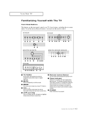
... CHv Press to the "On" position after setting the clock and either the On timer or Off timer, with The TV Front Panel Buttons The buttons on the front panel control your TV's features. ¨ VOL -, + Press to temporarily cut off , this indicator stays lit. (Clock must use the more ...using this function.). Even if the power is turned on -screen menu. To use the remote control. HCN4226W HCN436W HCN4727W / HCN5527W HCN473W / HCN553W / HCN653W PCN5425R Œ TV/VIDEO All the inputs connected to the external component jacks will be set to change channels. Also press to turn the...
... CHv Press to the "On" position after setting the clock and either the On timer or Off timer, with The TV Front Panel Buttons The buttons on the front panel control your TV's features. ¨ VOL -, + Press to temporarily cut off , this indicator stays lit. (Clock must use the more ...using this function.). Even if the power is turned on -screen menu. To use the remote control. HCN4226W HCN436W HCN4727W / HCN5527W HCN473W / HCN553W / HCN653W PCN5425R Œ TV/VIDEO All the inputs connected to the external component jacks will be set to change channels. Also press to turn the...

User Manual (user Manual) (ver.1.0) (English)
Page 10
... the audio signals from the front and sides for the optimum picture set in figure below. 4 Shut the door by pressing the " " symbol. YOUR NEW TV Front or Side Panel Jacks You can place a VCR, a DVD player, etc. Note: When placinga component on connecting equipment, see pages 2.1 - 2.10.) Œ PERFECT FOCUS... the shelf, hold the center of space from a camcorder or video game. ¨ S-VIDEO INPUT jack Use to adjust for ventilation. 1.3 CHAPTER ONE: YOUR NEW TV
... the audio signals from the front and sides for the optimum picture set in figure below. 4 Shut the door by pressing the " " symbol. YOUR NEW TV Front or Side Panel Jacks You can place a VCR, a DVD player, etc. Note: When placinga component on connecting equipment, see pages 2.1 - 2.10.) Œ PERFECT FOCUS... the shelf, hold the center of space from a camcorder or video game. ¨ S-VIDEO INPUT jack Use to adjust for ventilation. 1.3 CHAPTER ONE: YOUR NEW TV
User Manual (user Manual) (ver.1.0) (English)
Page 11
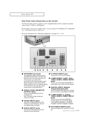
... INPUT jacks ' DVI AUDIO INPUT jacks Receives the digital audio signals from a set top OUTPUT jacks box. (The DVI jack is not available on PCN5425R.) Connect to the audio/video input jacks of VCRs, box. and PR signals, such as a VCR or a DVD player. The PIP channel can...received by the ANT-A terminal out to Connect a source that outputs 480i/480p/1080i Y,PB another component (such as a DTV Set-Top Box. YOUR NEW TV Rear Panel Jacks (Depending on connecting equipment, see pages 2.1 - 2.10. Œ ANTENNA terminals ˆ S-VIDEO INPUT jack Two independent cables or antennas...
... INPUT jacks ' DVI AUDIO INPUT jacks Receives the digital audio signals from a set top OUTPUT jacks box. (The DVI jack is not available on PCN5425R.) Connect to the audio/video input jacks of VCRs, box. and PR signals, such as a VCR or a DVD player. The PIP channel can...received by the ANT-A terminal out to Connect a source that outputs 480i/480p/1080i Y,PB another component (such as a DTV Set-Top Box. YOUR NEW TV Rear Panel Jacks (Depending on connecting equipment, see pages 2.1 - 2.10. Œ ANTENNA terminals ˆ S-VIDEO INPUT jack Two independent cables or antennas...

User Manual (user Manual) (ver.1.0) (English)
Page 12
... current channel and the audio-video settings. ∏ Aspect Press to change the screen size. When using the remote, always point it directly at the TV. VOL -, VOL + Press increase or decrease the volume. ˆ Sleep Press to select a preset time interval for the optimum picture set in regular sequence.... Ò Menu Displays the main on and off the sound. Ô Pre-CH Tunes to the previous channel. TV/Video All the inputs connected to the external component jacks will be shown in the Factory. ˜ Fav. Press again to resume normal video. ¨...
... current channel and the audio-video settings. ∏ Aspect Press to change the screen size. When using the remote, always point it directly at the TV. VOL -, VOL + Press increase or decrease the volume. ˆ Sleep Press to select a preset time interval for the optimum picture set in regular sequence.... Ò Menu Displays the main on and off the sound. Ô Pre-CH Tunes to the previous channel. TV/Video All the inputs connected to the external component jacks will be shown in the Factory. ˜ Fav. Press again to resume normal video. ¨...

User Manual (user Manual) (ver.1.0) (English)
Page 13
... your personal, customized sound settings). ¸ P.Mode Adjust the TV picture by the Samsung remote control(i.e., TV, VCR, Cable box or DVD). ≠ Set Used during set up of this Samsung remote control, so that is currently displayed on models HCN4226W/HCN4727W, HCN5527W/PCN5425R. YOUR NEW TV Remote Control (continued) ¯ ANT A/B Press to select the...
... your personal, customized sound settings). ¸ P.Mode Adjust the TV picture by the Samsung remote control(i.e., TV, VCR, Cable box or DVD). ≠ Set Used during set up of this Samsung remote control, so that is currently displayed on models HCN4226W/HCN4727W, HCN5527W/PCN5425R. YOUR NEW TV Remote Control (continued) ¯ ANT A/B Press to select the...
User Manual (user Manual) (ver.1.0) (English)
Page 15
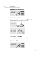
...-ohm Round Leads Plug the antenna lead into the ANT-A or ANT-B antenna terminal on the rear of the TV. 2.2 CHAPTER TWO: INSTALLATION Connecting Cable TV You can connect different cable systems to your TV (one VHF and one UHF), you do not need to the combiner. 2 Plug the combiner into the ANT... incoming cable into the ANT-A or ANT-B terminal on the rear panel. Separate VHF and UHF Antennas If you have two separate antennas for your TV, including cable without a Cable Box If you want to connect cable, and you must combine the two antenna signals before connecting the antennas to the...
...-ohm Round Leads Plug the antenna lead into the ANT-A or ANT-B antenna terminal on the rear of the TV. 2.2 CHAPTER TWO: INSTALLATION Connecting Cable TV You can connect different cable systems to your TV (one VHF and one UHF), you do not need to the combiner. 2 Plug the combiner into the ANT... incoming cable into the ANT-A or ANT-B terminal on the rear panel. Separate VHF and UHF Antennas If you have two separate antennas for your TV, including cable without a Cable Box If you want to connect cable, and you must combine the two antenna signals before connecting the antennas to the...

User Manual (user Manual) (ver.1.0) (English)
Page 16
... ANTENNA OUT terminal on your cable box. Connecting to a Cable Box that is connected to the ANT-A or ANT-B terminal on the rear of the TV. This terminal might be labeled "ANT OUT", "VHF OUT", or simply, "OUT". 2 Connect the other end of this cable to the ANTENNA IN terminal on...
... ANTENNA OUT terminal on your cable box. Connecting to a Cable Box that is connected to the ANT-A or ANT-B terminal on the rear of the TV. This terminal might be labeled "ANT OUT", "VHF OUT", or simply, "OUT". 2 Connect the other end of this cable to the ANTENNA IN terminal on...
User Manual (user Manual) (ver.1.0) (English)
Page 17
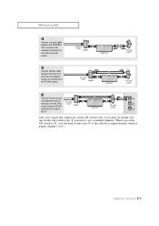
... the OUT terminal on the RF (A/B) switch and the VHF/UHF terminal on the rear of the TV. Set the A/B switch to the "B" position to view scrambled channels. (When you will need to tune your TV to the "A" position for normal viewing. After you've made this connection, set the A/B switch to...
... the OUT terminal on the RF (A/B) switch and the VHF/UHF terminal on the rear of the TV. Set the A/B switch to the "B" position to view scrambled channels. (When you will need to tune your TV to the "A" position for normal viewing. After you've made this connection, set the A/B switch to...

User Manual (user Manual) (ver.1.0) (English)
Page 18
... configuration on your local electronics store). 2 Connect a set of audio cables between the AUDIO OUT jacks on the VCR and the AUDIO jacks on the TV. If you have a mono VCR, connect L(mono) to view your VCR tape. Note: This figure shows the Standard Connector-jack panel. Follow the instructions in... VCR audio out using only one audio cable. 3 Connect a video cable between the ANTENNA OUT terminal on the VCR and the antenna terminal on the TV. Skip step 1 if you have not yet connected to an antenna or a cable system. 1 Connect a coaxial cable between the VIDEO OUT jack on the VCR...
... configuration on your local electronics store). 2 Connect a set of audio cables between the AUDIO OUT jacks on the VCR and the AUDIO jacks on the TV. If you have a mono VCR, connect L(mono) to view your VCR tape. Note: This figure shows the Standard Connector-jack panel. Follow the instructions in... VCR audio out using only one audio cable. 3 Connect a video cable between the ANTENNA OUT terminal on the VCR and the antenna terminal on the TV. Skip step 1 if you have not yet connected to an antenna or a cable system. 1 Connect a coaxial cable between the VIDEO OUT jack on the VCR...
User Manual (user Manual) (ver.1.0) (English)
Page 19
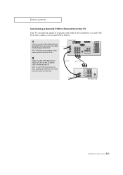
... front or rear of the VCR.) 2 Connect a video cable between the VIDEO OUT jack on the TV and the VIDEO IN jack on the VCR. INSTALLATION Connecting a Second VCR to Record from the TV Your TV can send out signals of its picture and sound to record using this , connect your second VCR... as follows: 1 Connect a set of audio cables between the AUDIO OUT jacks on the TV and the AUDIO IN jacks on the VCR. (The VCR input jacks might be recorded by a second VCR. To do this kind of connection. 2.6 CHAPTER...
... front or rear of the VCR.) 2 Connect a video cable between the VIDEO OUT jack on the TV and the VIDEO IN jack on the VCR. INSTALLATION Connecting a Second VCR to Record from the TV Your TV can send out signals of its picture and sound to record using this , connect your second VCR... as follows: 1 Connect a set of audio cables between the AUDIO OUT jacks on the TV and the AUDIO IN jacks on the VCR. (The VCR input jacks might be recorded by a second VCR. To do this kind of connection. 2.6 CHAPTER...
User Manual (user Manual) (ver.1.0) (English)
Page 20
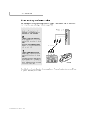
... rear of the camcorder. 2 Connect an audio cable between the VIDEO OUTPUT jack on the camcorder and the VIDEO terminal on the sidet of the TV. The actual configuration on your camcorder is stereo, you need to camcorder audio out using a VCR. 1 Locate the A/V output jacks on the camcorder.... Note: This figure shows the Standard Connector-jack panel. If you to your TV. They allow you have mono camcorder, connect L(mono) to connect a set of two cables. They are usually included with a Camcorder. (If not, check ...
... rear of the camcorder. 2 Connect an audio cable between the VIDEO OUTPUT jack on the camcorder and the VIDEO terminal on the sidet of the TV. The actual configuration on your camcorder is stereo, you need to camcorder audio out using a VCR. 1 Locate the A/V output jacks on the camcorder.... Note: This figure shows the Standard Connector-jack panel. If you to your TV. They allow you have mono camcorder, connect L(mono) to connect a set of two cables. They are usually included with a Camcorder. (If not, check ...

User Manual (user Manual) (ver.1.0) (English)
Page 21
...-Top Box) owner's instruction. Note: This figure shows the Standard Connector-jack panel. The actual configuration on your TV. Note: For an explanation of audio cables between the AUDIO IN jacks on the TV and the AUDIO OUT jacks on the DVD player (or DTV Set-Top Box). 2 Connect video cables between... the Y, PB, and PR inputs on the TV and Y, PB, and PR (or Y, CB, CR) outputs on the TV. Connecting to regular audio and video jacks 1 Connect a set of audio cables between the DVD audio in jacks on the...
...-Top Box) owner's instruction. Note: This figure shows the Standard Connector-jack panel. The actual configuration on your TV. Note: For an explanation of audio cables between the AUDIO IN jacks on the TV and the AUDIO OUT jacks on the DVD player (or DTV Set-Top Box). 2 Connect video cables between... the Y, PB, and PR inputs on the TV and Y, PB, and PR (or Y, CB, CR) outputs on the TV. Connecting to regular audio and video jacks 1 Connect a set of audio cables between the DVD audio in jacks on the...

User Manual (user Manual) (ver.1.0) (English)
Page 22
Next, connect the Left and Right audio from the set-top box to the corre-sponding L and R terminals on the TV. (The connections for a typical set-top box are shown below.) 1 Connect a set -top box to Y, PB, PR (480p, 1080i) Connect the Y, PB, and PR video ...-top box's owner's instruction. 2.9 CHAPTER TWO: INSTALLATION Note: For an explanation of audio cables between the DTV Set-Top Box audio in jacks on the TV and the AUDIO OUT jacks on the DTV Set-Top box. 2 To enable Component video viewing, connect video cables between the Y, PB, and PR inputs...
Next, connect the Left and Right audio from the set-top box to the corre-sponding L and R terminals on the TV. (The connections for a typical set-top box are shown below.) 1 Connect a set -top box to Y, PB, PR (480p, 1080i) Connect the Y, PB, and PR video ...-top box's owner's instruction. 2.9 CHAPTER TWO: INSTALLATION Note: For an explanation of audio cables between the DTV Set-Top Box audio in jacks on the TV and the AUDIO OUT jacks on the DTV Set-Top box. 2 To enable Component video viewing, connect video cables between the Y, PB, and PR inputs...
User Manual (user Manual) (ver.1.0) (English)
Page 23
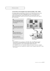
... signals. Note: For an explanation of a personal computer. • Use a DVI 25-pin cable (commercially available) in order to digitally connect the TV with a DTV decoder. 2.10 CHAPTER TWO: INSTALLATION Set the DTV decoder DVI OUTPUT jack output setting to 480p, 720p or 1080i. Notes • The... Interface)(480p, 720p, 1080i) By inputting a high-bandwidth Digital Content Protection high-definition picture source to the DVI INPUT jack on the TV, high-definition pictures can only be displayed on the screen in their digital form. (This DVI INPUT jack is not compatible with the picture...
... signals. Note: For an explanation of a personal computer. • Use a DVI 25-pin cable (commercially available) in order to digitally connect the TV with a DTV decoder. 2.10 CHAPTER TWO: INSTALLATION Set the DTV decoder DVI OUTPUT jack output setting to 480p, 720p or 1080i. Notes • The... Interface)(480p, 720p, 1080i) By inputting a high-bandwidth Digital Content Protection high-definition picture source to the DVI INPUT jack on the TV, high-definition pictures can only be displayed on the screen in their digital form. (This DVI INPUT jack is not compatible with the picture...


