User Manual (ENGLISH)
Page 7
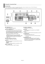
... a device with a DVI output. You should use a locking device, contact the dealer where you purchased the TV. HDMI/DVI IN terminal does not support PC. - AV OUT Connect to HDMI) for video connection, and the... power cord. KENSINGTON LOCK The Kensington lock (optional) is needed for an HDMI to an antenna or cable TV system. English-5 DVI IN, HDMI/DVI IN 1,2 Connect to the video and audio output jacks on your PC... different depending on connecting equipment, see pages 8-14. Viewing the Connection Panel Rear Panel Jacks Use the rear panel jacks to a Digital Audio component.
... a device with a DVI output. You should use a locking device, contact the dealer where you purchased the TV. HDMI/DVI IN terminal does not support PC. - AV OUT Connect to HDMI) for video connection, and the... power cord. KENSINGTON LOCK The Kensington lock (optional) is needed for an HDMI to an antenna or cable TV system. English-5 DVI IN, HDMI/DVI IN 1,2 Connect to the video and audio output jacks on your PC... different depending on connecting equipment, see pages 8-14. Viewing the Connection Panel Rear Panel Jacks Use the rear panel jacks to a Digital Audio component.
User Manual (ENGLISH)
Page 10
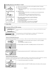
...batteries reversed? 3. If you have two separate antennas for about 23 feet from the twin leads under the screws on the back of the TV. Antennas with 300 Ω Flat Twin Leads If you are using the remote control for a long time. This procedure requires an optional ... Connections If the remote control doesn't work, check the following: 1. Are the plus and minus ends of the rear panel. Are the batteries drained? 4. Place the wires from the TV. (Assuming typical TV usage, the batteries last for your antenna has a set of the batteries with 300 Ω Flat Twin Leads...
...batteries reversed? 3. If you have two separate antennas for about 23 feet from the twin leads under the screws on the back of the TV. Antennas with 300 Ω Flat Twin Leads If you are using the remote control for a long time. This procedure requires an optional ... Connections If the remote control doesn't work, check the following: 1. Are the plus and minus ends of the rear panel. Are the batteries drained? 4. Place the wires from the TV. (Assuming typical TV usage, the batteries last for your antenna has a set of the batteries with 300 Ω Flat Twin Leads...
User Manual (ENGLISH)
Page 12
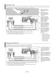
...your local electronics store.) Each S-VHS VCR has a different back panel configuration. ANT 1 IN ANT 2 IN (AIR) (CABLE) 1. Connect the cable or antenna to the ANT IN terminal on the TV. 5. Connecting an S-VHS VCR Your Samsung TV can be connected to an S-Video signal from the back of... Cable (Not supplied) 1 RF Cable (Not supplied) An S-Video cable is stereo, you have a "mono" (non-stereo) VCR, use of the TV. VCR Rear Panel TV Rear Panel 2. Connect Audio Cables between the S-VIDEO OUT jack on the VCR and the AV IN1 [S-VIDEO] jack on pages 8-9). English-10 Connect an RF Cable...
...your local electronics store.) Each S-VHS VCR has a different back panel configuration. ANT 1 IN ANT 2 IN (AIR) (CABLE) 1. Connect the cable or antenna to the ANT IN terminal on the TV. 5. Connecting an S-VHS VCR Your Samsung TV can be connected to an S-Video signal from the back of... Cable (Not supplied) 1 RF Cable (Not supplied) An S-Video cable is stereo, you have a "mono" (non-stereo) VCR, use of the TV. VCR Rear Panel TV Rear Panel 2. Connect Audio Cables between the S-VIDEO OUT jack on the VCR and the AV IN1 [S-VIDEO] jack on pages 8-9). English-10 Connect an RF Cable...
User Manual (ENGLISH)
Page 13
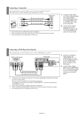
...1 S-Video Cable (Not supplied) or 1 Video Cable (Not supplied) 2 Audio Cable (Not supplied) TV Side Panel Each Camcorder has a different back panel configuration. Connecting a DVD Player/Set-Top Box The rear panel jacks on the camcorder. 2. Component video separates the video into Y (Luminance (brightness)), Pb (Blue) .... Connect Audio Cables between the COMPONENT IN 1 or 2 [Y, PB, PR] jacks on the TV and the COMPONENT [Y, PB, PR] jacks on the DVD player. DVD Player/Set-Top Box TV Rear Panel 2 Audio Cable (Not supplied) 1 Component Cable (Not supplied) 1. For example, if connecting...
...1 S-Video Cable (Not supplied) or 1 Video Cable (Not supplied) 2 Audio Cable (Not supplied) TV Side Panel Each Camcorder has a different back panel configuration. Connecting a DVD Player/Set-Top Box The rear panel jacks on the camcorder. 2. Component video separates the video into Y (Luminance (brightness)), Pb (Blue) .... Connect Audio Cables between the COMPONENT IN 1 or 2 [Y, PB, PR] jacks on the TV and the COMPONENT [Y, PB, PR] jacks on the DVD player. DVD Player/Set-Top Box TV Rear Panel 2 Audio Cable (Not supplied) 1 Component Cable (Not supplied) 1. For example, if connecting...
User Manual (ENGLISH)
Page 14
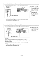
.../Set-Top Box. The difference between the HDMI/DVI IN 1 or HDMI/DVI IN 2 connector on the TV and the DVI connector on the DVD player/Set-Top Box. 2. DVD Player/Set-Top Box TV Rear Panel 2 Audio Cable (Not supplied) 1 DVI to HDMI Cable (Not supplied) Each DVD player/STB has a different... back panel configuration. Connecting a DVD Player/Set-Top Box via HDMI This connection can only be made if ...
.../Set-Top Box. The difference between the HDMI/DVI IN 1 or HDMI/DVI IN 2 connector on the TV and the DVI connector on the DVD player/Set-Top Box. 2. DVD Player/Set-Top Box TV Rear Panel 2 Audio Cable (Not supplied) 1 DVI to HDMI Cable (Not supplied) Each DVD player/STB has a different... back panel configuration. Connecting a DVD Player/Set-Top Box via HDMI This connection can only be made if ...
User Manual (ENGLISH)
Page 15
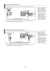
...color of cables with a Ferrite Core. 1. We recommend the use of the TV, and adjust the volume level with the system's volume control. English-13 Connecting a Digital Audio System The rear panel jacks on your TV make it easy to connect a Digital Audio System to the "DIGITAL AUDIO OUT...Optical Cable between the AV OUT [R-AUDIO-L] on the TV and AUDIO IN [R-AUDIO-L] on the Digital Audio System. When a Digital Audio System is connected to your TV. Connecting an Amplifier/DVD Home Theater Amplifier/DVD Home Theater TV Rear Panel Audio Cable (Not supplied) Each external input source device...
...color of cables with a Ferrite Core. 1. We recommend the use of the TV, and adjust the volume level with the system's volume control. English-13 Connecting a Digital Audio System The rear panel jacks on your TV make it easy to connect a Digital Audio System to the "DIGITAL AUDIO OUT...Optical Cable between the AV OUT [R-AUDIO-L] on the TV and AUDIO IN [R-AUDIO-L] on the Digital Audio System. When a Digital Audio System is connected to your TV. Connecting an Amplifier/DVD Home Theater Amplifier/DVD Home Theater TV Rear Panel Audio Cable (Not supplied) Each external input source device...
User Manual (ENGLISH)
Page 16
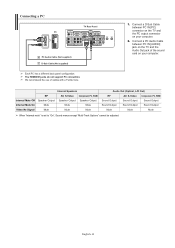
...-Track Options" cannot be adjusted. English-14 Connect a D-Sub Cable between PC IN [AUDIO] jack on the TV and the Audio Out jack of cables with a Ferrite Core. 1. Connecting a PC PC TV Rear Panel 2 PC Audio Cable (Not supplied) 1 D-Sub Cable (Not supplied) Each PC has a different back... panel configuration. Connect a PC Audio Cable between PC IN [PC] connector on the TV and the PC output connector on your computer. 2. We ...
...-Track Options" cannot be adjusted. English-14 Connect a D-Sub Cable between PC IN [AUDIO] jack on the TV and the Audio Out jack of cables with a Ferrite Core. 1. Connecting a PC PC TV Rear Panel 2 PC Audio Cable (Not supplied) 1 D-Sub Cable (Not supplied) Each PC has a different back... panel configuration. Connect a PC Audio Cable between PC IN [PC] connector on the TV and the PC output connector on your computer. 2. We ...
User Manual (ENGLISH)
Page 34
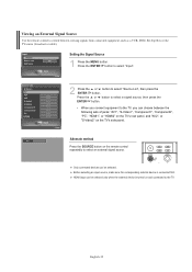
...following sets of jacks: "AV1", "S-Video1", "Component1", "Component2", "PC", "HDMI1", or "HDMI2" on the TV's rear panel, and "AV2", or "S-Video2" on and connected to the TV. Only connected devices can be selected only when the external device is connected first. Viewing an External Signal Source Use ...cable). Before selecting an input source, make sure the corresponding external device is turned on the TV's side panel. Press the ENTER button to select "Input". 2 Press the or button to the TV, you can be selected. Setting the Signal Source 1 Press the MENU button. Press the...
...following sets of jacks: "AV1", "S-Video1", "Component1", "Component2", "PC", "HDMI1", or "HDMI2" on the TV's rear panel, and "AV2", or "S-Video2" on and connected to the TV. Only connected devices can be selected only when the external device is connected first. Viewing an External Signal Source Use ...cable). Before selecting an input source, make sure the corresponding external device is turned on the TV's side panel. Press the ENTER button to select "Input". 2 Press the or button to the TV, you can be selected. Setting the Signal Source 1 Press the MENU button. Press the...
User Manual (ENGLISH)
Page 89
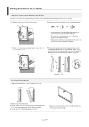
... the 4 screws in step 2 (plastic hanger + screw ) to the rear holes of the product to adjust the angle. Make sure to reinsert and...angle between -2° and 15°. Installing the Wall Mount Kit (LN-S4695D) Fixing the TV panel to the wall attachment panel bracket The shape of the product may not stay in the center and pull it is firmly fixed...the bracket. Wall Bracket Wall 1. Then place the product ( ) so that it forward (direction of the product. LCD TV How to Adjust Mounting Angle Adjust the bracket angle to -2° before installing it is properly fixed to the left ...
... the 4 screws in step 2 (plastic hanger + screw ) to the rear holes of the product to adjust the angle. Make sure to reinsert and...angle between -2° and 15°. Installing the Wall Mount Kit (LN-S4695D) Fixing the TV panel to the wall attachment panel bracket The shape of the product may not stay in the center and pull it is firmly fixed...the bracket. Wall Bracket Wall 1. Then place the product ( ) so that it forward (direction of the product. LCD TV How to Adjust Mounting Angle Adjust the bracket angle to -2° before installing it is properly fixed to the left ...
User Manual (ENGLISH)
Page 91
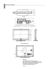
Refer to dimensions prior to change without prior notice. English-89 Some dimensions are not necessarily to scale. Dimensions (LN-S4095D) TOP VIEW JACK PANEL DETAIL 3.25" H x 9.92" W @ 12.98 " UP FROM BOTTOM FRONT VIEW/SIDE VIEW REAR VIEW NOTE: All drawings are subject to performing installation of your TV. Not responsible for typographical or printed errors. © 2006 Samsung Electronics America, Inc.
Refer to dimensions prior to change without prior notice. English-89 Some dimensions are not necessarily to scale. Dimensions (LN-S4095D) TOP VIEW JACK PANEL DETAIL 3.25" H x 9.92" W @ 12.98 " UP FROM BOTTOM FRONT VIEW/SIDE VIEW REAR VIEW NOTE: All drawings are subject to performing installation of your TV. Not responsible for typographical or printed errors. © 2006 Samsung Electronics America, Inc.
User Manual (ENGLISH)
Page 92
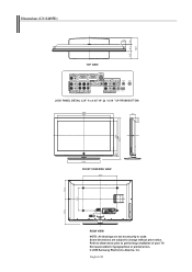
Not responsible for typographical or printed errors. © 2006 Samsung Electronics America, Inc. Some dimensions are not necessarily to scale. English-90 Refer to dimensions prior to performing installation of your TV. Dimensions (LN-S4695D) TOP VIEW JACK PANEL DETAIL 3.25" H x 9.92" W @ 12.98 " UP FROM BOTTOM FRONT VIEW/SIDE VIEW REAR VIEW NOTE: All drawings are subject to change without prior notice.
Not responsible for typographical or printed errors. © 2006 Samsung Electronics America, Inc. Some dimensions are not necessarily to scale. English-90 Refer to dimensions prior to performing installation of your TV. Dimensions (LN-S4695D) TOP VIEW JACK PANEL DETAIL 3.25" H x 9.92" W @ 12.98 " UP FROM BOTTOM FRONT VIEW/SIDE VIEW REAR VIEW NOTE: All drawings are subject to change without prior notice.


