
User Manual (ENGLISH)
Page 2
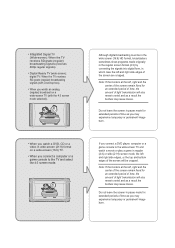
...time as you may experience temporary or permanent image burn. Precautions When Displaying a Still Image A still image may cause permanent damage to the TV screen. • Digital Ready TV: When you select the regular screen (4:3) mode to watch an SD-grade digital broadcast (and the set-top box output is 480p). •...; Digital Ready TV: When you select the wide screen (16:9) mode to watch the program but the top and bottom edges of the screen will be cropped. When ...
...time as you may experience temporary or permanent image burn. Precautions When Displaying a Still Image A still image may cause permanent damage to the TV screen. • Digital Ready TV: When you select the regular screen (4:3) mode to watch an SD-grade digital broadcast (and the set-top box output is 480p). •...; Digital Ready TV: When you select the wide screen (16:9) mode to watch the program but the top and bottom edges of the screen will be cropped. When ...
User Manual (ENGLISH)
Page 3
... mode for extended periods of the screen are cropped. • Integrated Digital TV (Wide-screen): When the TV receives SD-grade (regular) broadcasting signals (receives 480p regular signals). • Digital Ready TV (wide-screen): digital TV: When the TV receives SD-grade (regular) broadcasting signals (with a set-top box). &#...8226; When you watch an analog (regular) broadcast on a wide-screen TV (with the 4:3 screen mode selected). • When you watch a movie or play a game in regular (4:3) or wide (21:9) screen mode, ...
... mode for extended periods of the screen are cropped. • Integrated Digital TV (Wide-screen): When the TV receives SD-grade (regular) broadcasting signals (receives 480p regular signals). • Digital Ready TV (wide-screen): digital TV: When the TV receives SD-grade (regular) broadcasting signals (with a set-top box). &#...8226; When you watch an analog (regular) broadcast on a wide-screen TV (with the 4:3 screen mode selected). • When you watch a movie or play a game in regular (4:3) or wide (21:9) screen mode, ...

User Manual (ENGLISH)
Page 4
... Connecting VHF and UHF Antennas 7 Antennas with 300-ohm Flat Twin Leads 7 Antennas with 75-ohm Round Leads 8 Separate VHF and UHF Antennas 8 Connecting Cable TV 9 Cable without a Cable Box 9 Connecting to a Cable Box that Descrambles All Channels . . . . . 9 Connecting to a Cable Box that Descrambles Some... Channels . . . 9 Connecting a VCR 11 Connecting an S-VHS VCR 13 Connecting a DVD Player 14 Connecting a Digital TV Set-top box 15 Connecting an Amplifier/DVD Home Theater 15 Connecting a DVD/Set-top box via DVI 16 Connecting a DVD/Set-top box via...
... Connecting VHF and UHF Antennas 7 Antennas with 300-ohm Flat Twin Leads 7 Antennas with 75-ohm Round Leads 8 Separate VHF and UHF Antennas 8 Connecting Cable TV 9 Cable without a Cable Box 9 Connecting to a Cable Box that Descrambles All Channels . . . . . 9 Connecting to a Cable Box that Descrambles Some... Channels . . . 9 Connecting a VCR 11 Connecting an S-VHS VCR 13 Connecting a DVD Player 14 Connecting a Digital TV Set-top box 15 Connecting an Amplifier/DVD Home Theater 15 Connecting a DVD/Set-top box via DVI 16 Connecting a DVD/Set-top box via...
User Manual (ENGLISH)
Page 5
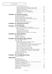
... Mute 48 Selecting the Main or Sub (PIP) Sound 49 Chapter 6: Channel Control Fine Tuning Channels 50 Chapter 7: PC Display Using Your TV as a Computer (PC) Display 51 Setting Up Your PC Software (Based on Windows XP 51 How to Auto Adjust 52 Adjusting the Screen... the stand 77 Disconnecting the stand 77 Installing the Wall Mount Kit (LN-R238W / LN-R237W / LN-R268W / LN-R2668W / LN-R267W) . . . 78 Installing the Wall Mount Kit (LN-R328W / LN-R3228W / LN-R327W 79 Using the Anti-Theft Kensington Lock 80 Using Your TV in Another Country 80 Specifications 81 Display Modes 83 Contents-2
... Mute 48 Selecting the Main or Sub (PIP) Sound 49 Chapter 6: Channel Control Fine Tuning Channels 50 Chapter 7: PC Display Using Your TV as a Computer (PC) Display 51 Setting Up Your PC Software (Based on Windows XP 51 How to Auto Adjust 52 Adjusting the Screen... the stand 77 Disconnecting the stand 77 Installing the Wall Mount Kit (LN-R238W / LN-R237W / LN-R268W / LN-R2668W / LN-R267W) . . . 78 Installing the Wall Mount Kit (LN-R328W / LN-R3228W / LN-R327W 79 Using the Anti-Theft Kensington Lock 80 Using Your TV in Another Country 80 Specifications 81 Display Modes 83 Contents-2
User Manual (ENGLISH)
Page 6
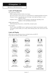
...Owner's Instructions M4 X L16 Stand Screw (6002-001294) x 4 Stand (23", 26" BN96-01727A) (32" BN96-01733A) English-1 Cleaning Cloth (BN63-01798A) LN-R238W, LN-R268W, LN-R2668W, LN-R328W, LN-R3228W The Anynet system enables you to your preference by adjusting pink,blue ...and green. - Brightness Sensor: Adjusts the screen brightness automatically depending on the brightness of Parts Please make sure the following items are missing, contact your LCD TV...
...Owner's Instructions M4 X L16 Stand Screw (6002-001294) x 4 Stand (23", 26" BN96-01727A) (32" BN96-01733A) English-1 Cleaning Cloth (BN63-01798A) LN-R238W, LN-R268W, LN-R2668W, LN-R328W, LN-R3228W The Anynet system enables you to your preference by adjusting pink,blue ...and green. - Brightness Sensor: Adjusts the screen brightness automatically depending on the brightness of Parts Please make sure the following items are missing, contact your LCD TV...
User Manual (ENGLISH)
Page 7
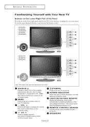
...POWER) Press to select items on the on -screen menu. SPEAKERS English-2 LN-R3228W - LN-R267W - LIGHT DETECTING SENSOR Adjusts the brightness of the screen automatically by mode. LN-R327W Note: The product color may vary depending on the TV. CH Press to decrease or increase the volume. Also used to turn the...see an on-screen menu of the Panel The buttons on the lower-right panel control your choice on the on -screen menu. LN-R238W - LN-R237W - This sensor works when the Brightness Sensor is on -screen menu. To use the more advanced features, you must use the remote control...
...POWER) Press to select items on the on -screen menu. SPEAKERS English-2 LN-R3228W - LN-R267W - LIGHT DETECTING SENSOR Adjusts the brightness of the screen automatically by mode. LN-R327W Note: The product color may vary depending on the TV. CH Press to decrease or increase the volume. Also used to turn the...see an on-screen menu of the Panel The buttons on the lower-right panel control your choice on the on -screen menu. LN-R238W - LN-R237W - This sensor works when the Brightness Sensor is on -screen menu. To use the more advanced features, you must use the remote control...
User Manual (ENGLISH)
Page 8
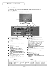
... as a VCR or a DVD player. PC IN Connect to the video and audio output jack on DVI-IN for service only. Anynet Refer to a cable TV system. HDMI/DVI IN Connect to the HDMI jack of external headphones for external devices with HDMI output. G E N E R A L I N F O R M AT I O N Rear Panel Jacks Use the rear...
... as a VCR or a DVD player. PC IN Connect to the video and audio output jack on DVI-IN for service only. Anynet Refer to a cable TV system. HDMI/DVI IN Connect to the HDMI jack of external headphones for external devices with HDMI output. G E N E R A L I N F O R M AT I O N Rear Panel Jacks Use the rear...

User Manual (ENGLISH)
Page 9
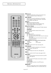
... 21) CAPTION Controls the caption decoder. (See page 71) PIP Picture-in-Picture ON/OFF. (See page 40) SLEEP Press to select a time for the TV to turn off . (See page 19) STILL Press to a distance of the available video sources. (See page 27) INFO Use to see information on the... page 19) VOL + and VOL Press to increase or decrease the volume. (See page 20) SOURCE Press to display all of about 23 feet from the TV. POWER Turns the TV on -screen menu items and change the channel. +100 Press to select channels over 100. English-4 G E N E R A L I N F O R M AT I O N Remote Control You can use...
... 21) CAPTION Controls the caption decoder. (See page 71) PIP Picture-in-Picture ON/OFF. (See page 40) SLEEP Press to select a time for the TV to turn off . (See page 19) STILL Press to a distance of the available video sources. (See page 27) INFO Use to see information on the... page 19) VOL + and VOL Press to increase or decrease the volume. (See page 20) SOURCE Press to display all of about 23 feet from the TV. POWER Turns the TV on -screen menu items and change the channel. +100 Press to select channels over 100. English-4 G E N E R A L I N F O R M AT I O N Remote Control You can use...
User Manual (ENGLISH)
Page 10
...Pause - G E N E R A L I N F O R M AT I O N Anynet Press the Anynet button to bring up the Anynet menu. (Refer to "Anynet AV Owner's Instructions".) S.MODE Adjusts the TV sound by selecting one of the preset factory settings (or selects your remote does not work, change the screen size. (See page 33) PC Press... of the screen shows the original image.(See page 35) VCR/DVD Functions (Only Anynet mode) - Stop - Press to automatically store selected TV/Cable channels. (See page 25) ADD/DEL Use to store and delete channels to change the batteries and press the RESET button for 2-3 ...
...Pause - G E N E R A L I N F O R M AT I O N Anynet Press the Anynet button to bring up the Anynet menu. (Refer to "Anynet AV Owner's Instructions".) S.MODE Adjusts the TV sound by selecting one of the preset factory settings (or selects your remote does not work, change the screen size. (See page 33) PC Press... of the screen shows the original image.(See page 35) VCR/DVD Functions (Only Anynet mode) - Stop - Press to automatically store selected TV/Cable channels. (See page 25) ADD/DEL Use to store and delete channels to change the batteries and press the RESET button for 2-3 ...

User Manual (ENGLISH)
Page 11
Is the TV power on? 2. Are the batteries drained? 4. The remote control can be using the remote control for about one year.) If the remote control doesn't work ... batteries. Are the plus and minus ends of the batteries with the diagram inside the compartment. 3 Replace the cover. Make sure to about 23 feet from the TV. (Assuming typical TV usage, the batteries last for a long time. G E N E R A L I N F O R M AT I O N Installing Batteries in a cool, dry place if you won't be used up to match...
Is the TV power on? 2. Are the batteries drained? 4. The remote control can be using the remote control for about one year.) If the remote control doesn't work ... batteries. Are the plus and minus ends of the batteries with the diagram inside the compartment. 3 Replace the cover. Make sure to about 23 feet from the TV. (Assuming typical TV usage, the batteries last for a long time. G E N E R A L I N F O R M AT I O N Installing Batteries in a cool, dry place if you won't be used up to match...
User Manual (ENGLISH)
Page 12
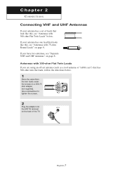
... (such as a roof antenna or "rabbit ears") that has 300-ohm twin flat leads, follow the directions below . If your antenna has a set of the TV. Chapter 2 CONNECTIONS Connecting VHF and UHF Antennas If your antenna has one lead that looks like this , see "Antennas with 75-ohm Round Leads" on...
... (such as a roof antenna or "rabbit ears") that has 300-ohm twin flat leads, follow the directions below . If your antenna has a set of the TV. Chapter 2 CONNECTIONS Connecting VHF and UHF Antennas If your antenna has one lead that looks like this , see "Antennas with 75-ohm Round Leads" on...

User Manual (ENGLISH)
Page 13
UHF VHF ANT IN English-8 CONNECTIONS Antennas with 75-ohm Round Leads 1 Plug the antenna lead into the ANT IN terminal on the back of the TV. This procedure requires an optional combiner-adapter (available at most electronics shops). 1 Connect both antenna leads to the TV. UHF VHF 2 Plug the combiner into the ANT IN terminal on the back of the TV. Separate VHF and UHF Antennas If you have two separate antennas for your TV (one VHF and one UHF), you must combine the two antenna signals before connecting the antennas to the combiner.
UHF VHF ANT IN English-8 CONNECTIONS Antennas with 75-ohm Round Leads 1 Plug the antenna lead into the ANT IN terminal on the back of the TV. This procedure requires an optional combiner-adapter (available at most electronics shops). 1 Connect both antenna leads to the TV. UHF VHF 2 Plug the combiner into the ANT IN terminal on the back of the TV. Separate VHF and UHF Antennas If you have two separate antennas for your TV (one VHF and one UHF), you must combine the two antenna signals before connecting the antennas to the combiner.
User Manual (ENGLISH)
Page 14
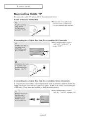
...-9 Connecting to a Cable Box that Descrambles All Channels 1 Find the cable that is connected to the ANT IN terminal on the back of the TV. Connecting to a Cable Box that is connected to the ANT OUT terminal on back of RF cable. (These items are available at most electronics...you do not need a two-way splitter, an RF (A/B) switch, and four lengths of the TV. You will need a cable box to view unscrambled cable channels. CONNECTIONS Connecting Cable TV To connect to a cable TV system, follow the instructions below . Cable without a Cable Box 1 Plug the incoming cable into the...
...-9 Connecting to a Cable Box that Descrambles All Channels 1 Find the cable that is connected to the ANT IN terminal on the back of the TV. Connecting to a Cable Box that is connected to the ANT OUT terminal on back of RF cable. (These items are available at most electronics...you do not need a two-way splitter, an RF (A/B) switch, and four lengths of the TV. You will need a cable box to view unscrambled cable channels. CONNECTIONS Connecting Cable TV To connect to a cable TV system, follow the instructions below . Cable without a Cable Box 1 Plug the incoming cable into the...
User Manual (ENGLISH)
Page 15
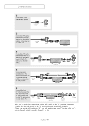
... Box RF (A/B) Switch 6 Connect the last RF cable between the other OUT terminal on the splitter and the A-IN terminal on the rear of the TV. Set the A/B switch to the "B" position to view scrambled channels. (When you set the A/B switch to "B", you 've made this cable to the cable box... on the cable box and the B-IN terminal on the cable box. Incoming cable Splitter Cable Box RF (A/B) Switch ANT IN TV Rear After you will need to tune your TV to a two-way splitter. Incoming cable Splitter Cable Box 4 Connect an RF cable between an OUTPUT terminal on the splitter and...
... Box RF (A/B) Switch 6 Connect the last RF cable between the other OUT terminal on the splitter and the A-IN terminal on the rear of the TV. Set the A/B switch to the "B" position to view scrambled channels. (When you set the A/B switch to "B", you 've made this cable to the cable box... on the cable box and the B-IN terminal on the cable box. Incoming cable Splitter Cable Box RF (A/B) Switch ANT IN TV Rear After you will need to tune your TV to a two-way splitter. Incoming cable Splitter Cable Box 4 Connect an RF cable between an OUTPUT terminal on the splitter and...

User Manual (ENGLISH)
Page 16
... cable or antenna from the back of the VCR. VCR Rear Panel TV Rear Panel RF Cable (Option) English-11 CONNECTIONS Connecting a VCR These instructions assume that you have already connected your TV to an antenna or a cable TV system (according to the ANT IN terminal on the back of the... TV. 2 Connect the cable or antenna to the instructions on pages 7-10). Incoming Cable or Antenna...
... cable or antenna from the back of the VCR. VCR Rear Panel TV Rear Panel RF Cable (Option) English-11 CONNECTIONS Connecting a VCR These instructions assume that you have already connected your TV to an antenna or a cable TV system (according to the ANT IN terminal on the back of the... TV. 2 Connect the cable or antenna to the instructions on pages 7-10). Incoming Cable or Antenna...

User Manual (ENGLISH)
Page 17
CONNECTIONS 4 Connect an audio cable between the VIDEO OUT jack on the VCR and the AV IN [VIDEO] jack on the TV. English-12 VCR Rear Panel TV Rear Panel Audio Cable (Option) Video Cable (Option) RF Cable (Option) Follow the instructions in "Viewing a VCR or Camcorder Tape" to the left and right... a video cable between the AUDIO OUT jacks on the VCR and the AV IN [R-AUDIO-L] jacks on the TV. VCR Rear Panel TV Rear Panel Audio Cable (Option) RF Cable (Option) If you have a "mono" (non-stereo) VCR, use the Y-connector (not supplied) to hook up to view ...
CONNECTIONS 4 Connect an audio cable between the VIDEO OUT jack on the VCR and the AV IN [VIDEO] jack on the TV. English-12 VCR Rear Panel TV Rear Panel Audio Cable (Option) Video Cable (Option) RF Cable (Option) Follow the instructions in "Viewing a VCR or Camcorder Tape" to the left and right... a video cable between the AUDIO OUT jacks on the VCR and the AV IN [R-AUDIO-L] jacks on the TV. VCR Rear Panel TV Rear Panel Audio Cable (Option) RF Cable (Option) If you have a "mono" (non-stereo) VCR, use the Y-connector (not supplied) to hook up to view ...

User Manual (ENGLISH)
Page 18
... S-Video Cable (Option) RF Cable (Option) An S-Video cable is usually included with an S-VHS VCR. (If not, check your TV. CONNECTIONS Connecting an S-VHS VCR Your Samsung TV can be connected to an S-Video signal from an S-VHS VCR. (This connection delivers a better picture as compared to a standard VHS ...antenna or cable to your VCR and your local electronics store.) * Each external input source device has a different back panel configuration. VCR Rear Panel TV Rear Panel Audio Cable (Option) RF Cable (Option) 3 Connect an S-Video cable between the AUDIO OUT jacks on the VCR and the AV...
... S-Video Cable (Option) RF Cable (Option) An S-Video cable is usually included with an S-VHS VCR. (If not, check your TV. CONNECTIONS Connecting an S-VHS VCR Your Samsung TV can be connected to an S-Video signal from an S-VHS VCR. (This connection delivers a better picture as compared to a standard VHS ...antenna or cable to your VCR and your local electronics store.) * Each external input source device has a different back panel configuration. VCR Rear Panel TV Rear Panel Audio Cable (Option) RF Cable (Option) 3 Connect an S-Video cable between the AUDIO OUT jacks on the VCR and the AV...

User Manual (ENGLISH)
Page 19
...Component In 1 also. * Each external input source device has a different back panel configuration. DVD Player Rear Panel Audio Cable (Option) Component Cable (Option) TV Rear Panel Note: For an explanation of Component video, see your TV. 1 Connect an audio cable between the COMPONENT IN 1 or COMPONENT IN 2 [PR, PB, Y] jacks on the... the AUDIO OUT jacks on the DVD player. CONNECTIONS Connecting a DVD Player The rear panel jacks on your TV make it easy to connect a DVD player to your DVD player owner's manual. For example, if connecting the video cable to Component In 1, connect ...
...Component In 1 also. * Each external input source device has a different back panel configuration. DVD Player Rear Panel Audio Cable (Option) Component Cable (Option) TV Rear Panel Note: For an explanation of Component video, see your TV. 1 Connect an audio cable between the COMPONENT IN 1 or COMPONENT IN 2 [PR, PB, Y] jacks on the... the AUDIO OUT jacks on the DVD player. CONNECTIONS Connecting a DVD Player The rear panel jacks on your TV make it easy to connect a DVD player to your DVD player owner's manual. For example, if connecting the video cable to Component In 1, connect ...

User Manual (ENGLISH)
Page 20
... external input source device has a different back panel configuration. Set-Top Box Rear Panel TV Rear Panel Audio Cable (Option) 2 Connect a component cable between the COMPONENT IN 1 or COMPONENT IN 2 [R-AUDIO-L] jacks on the TV and the AUDIO OUT jacks on the Set-top box. CONNECTIONS Connecting a Digital... TV Set-top box The connections for a typical Set-top box are shown below. 1 Connect an audio cable ...
... external input source device has a different back panel configuration. Set-Top Box Rear Panel TV Rear Panel Audio Cable (Option) 2 Connect a component cable between the COMPONENT IN 1 or COMPONENT IN 2 [R-AUDIO-L] jacks on the TV and the AUDIO OUT jacks on the Set-top box. CONNECTIONS Connecting a Digital... TV Set-top box The connections for a typical Set-top box are shown below. 1 Connect an audio cable ...

User Manual (ENGLISH)
Page 21
CONNECTIONS Connecting a DVD/Set-top box via DVI This can be applied only if there is the DVI Output connector on the external device. 1 Connect a DVI-to -HDMI Cable (Option) 2 Connect an audio cable between the HDMI/DVI connector on the TV and the DVI connector on the DVD player/Set-top box. DVD Player Rear Panel TV Rear Panel DVI-to -HDMI cable or DVI-HDMI adapter between the DVI IN [R-AUDIO-L] jack on the TV and the AUDIO OUT jacks on the DVD player/Set-top box. DVD Player Rear Panel TV Rear Panel Audio Cable (Option) DVI-to-HDMI Cable (Option) English-16
CONNECTIONS Connecting a DVD/Set-top box via DVI This can be applied only if there is the DVI Output connector on the external device. 1 Connect a DVI-to -HDMI Cable (Option) 2 Connect an audio cable between the HDMI/DVI connector on the TV and the DVI connector on the DVD player/Set-top box. DVD Player Rear Panel TV Rear Panel DVI-to -HDMI cable or DVI-HDMI adapter between the DVI IN [R-AUDIO-L] jack on the TV and the AUDIO OUT jacks on the DVD player/Set-top box. DVD Player Rear Panel TV Rear Panel Audio Cable (Option) DVI-to-HDMI Cable (Option) English-16


