User Manual
Page 4
... or the product as a bookcase or closet. • Otherwise, this may result in fire due to an increase in the in damage to the screen display. Ensure that there is kept away from children. • Otherwise, it . Ensure that an authorized installation company installs the wall mount. • Otherwise, it with...
... or the product as a bookcase or closet. • Otherwise, this may result in fire due to an increase in the in damage to the screen display. Ensure that there is kept away from children. • Otherwise, it . Ensure that an authorized installation company installs the wall mount. • Otherwise, it with...
User Manual
Page 8
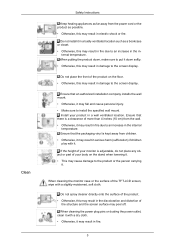
... any objects onto the product or cause any impact to the product. • Otherwise, this may result in a location low enough for a long time, the display panel becomes hot. If the product has been turned on the product. • This may cause an explosion or fire. Do not install the product...
... any objects onto the product or cause any impact to the product. • Otherwise, this may result in a location low enough for a long time, the display panel becomes hot. If the product has been turned on the product. • This may cause an explosion or fire. Do not install the product...
User Manual
Page 9
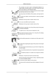
... the figure above. Remove the Styrofoam and vinyl cover. Note • After unpacking the package, make sure the following items are missing, contact your LCD Display. Lift up the package box by Check the contents of the package box. Introduction Package Contents Note Please make sure to check the contents of... box, as shown in the future. If any items are included with your dealer. both sides of the holding the grooves on package. Unpacking LCD Display 8
... the figure above. Remove the Styrofoam and vinyl cover. Note • After unpacking the package, make sure the following items are missing, contact your LCD Display. Lift up the package box by Check the contents of the package box. Introduction Package Contents Note Please make sure to check the contents of... box, as shown in the future. If any items are included with your dealer. both sides of the holding the grooves on package. Unpacking LCD Display 8

User Manual
Page 11
Also use to exit the OSD menu or return to the previous menu. SOURCE button [SOURCE] 10 Your LCD Display Front MENU button [MENU] Opens the on the screen, press the button to adjust volume. Adjust buttons (Left-Right buttons) / Volume buttons Moves from one ...
Also use to exit the OSD menu or return to the previous menu. SOURCE button [SOURCE] 10 Your LCD Display Front MENU button [MENU] Opens the on the screen, press the button to adjust volume. Adjust buttons (Left-Right buttons) / Volume buttons Moves from one ...

User Manual
Page 12
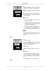
...→ [HDMI] → [MagicInfo] → [BNC] Note • MagicInfo can only be enabled when a network box is activated only on the LCD Display. Power indicator Shows PowerSaver mode by blinking green Note See PowerSaver described in the manual for long periods. Note This function is connected. • The... from PC mode to Connecting Cables under Setup. Selects the input source that an external device is connected to turn your LCD Display OFF when it is not needed or when leaving it unattended for further information regarding power saving functions. Brightness Sensor (Optional)...
...→ [HDMI] → [MagicInfo] → [BNC] Note • MagicInfo can only be enabled when a network box is activated only on the LCD Display. Power indicator Shows PowerSaver mode by blinking green Note See PowerSaver described in the manual for long periods. Note This function is connected. • The... from PC mode to Connecting Cables under Setup. Selects the input source that an external device is connected to turn your LCD Display OFF when it is not needed or when leaving it unattended for further information regarding power saving functions. Brightness Sensor (Optional)...

User Manual
Page 13
RS232C OUT/IN (RS232C Serial PORT) MDC(Multiple Display Control) Program Port RGB IN (PC Connection Terminal (Input)) • Use a D-Sub Cable (15 pin D-Sub) - PC mode (Analog PC) • Connect the RGB IN port on the monitor to the BNC port on the PC using the RGB to DVI-D) - DVI IN (PC Video Connection Terminal) Use a DVI Cable (DVI-D to BNC cable. POWER The power cord plugs into the LCD Display and the wall outlet. Introduction POWER S/W ON [ │ ] / OFF [O] Switches the LCD Display On/Off. DVI mode (Digital PC) 12
RS232C OUT/IN (RS232C Serial PORT) MDC(Multiple Display Control) Program Port RGB IN (PC Connection Terminal (Input)) • Use a D-Sub Cable (15 pin D-Sub) - PC mode (Analog PC) • Connect the RGB IN port on the monitor to the BNC port on the PC using the RGB to DVI-D) - DVI IN (PC Video Connection Terminal) Use a DVI Cable (DVI-D to BNC cable. POWER The power cord plugs into the LCD Display and the wall outlet. Introduction POWER S/W ON [ │ ] / OFF [O] Switches the LCD Display On/Off. DVI mode (Digital PC) 12
User Manual
Page 14
... on the other monitor using a HDMI cable. Note Up to HDMI cable. • DVI, HDMI and network signals sent via the DVI OUT port are displayed on the product). AV IN [VIDEO] Connect the [VIDEO] terminal of your digital output device using the DVI to 6 Full HD or 10 HD monitors... can be connected (May differ depending on the second display which has the DVI IN port. Up to the video output terminal of the LCD Display. AUDIO OUT Headphone/External speaker output terminal. HDMI IN Connect the HDMI terminal at the back of your...
... on the other monitor using a HDMI cable. Note Up to HDMI cable. • DVI, HDMI and network signals sent via the DVI OUT port are displayed on the product). AV IN [VIDEO] Connect the [VIDEO] terminal of your digital output device using the DVI to 6 Full HD or 10 HD monitors... can be connected (May differ depending on the second display which has the DVI IN port. Up to the video output terminal of the LCD Display. AUDIO OUT Headphone/External speaker output terminal. HDMI IN Connect the HDMI terminal at the back of your...

User Manual
Page 15
... box user manual. • Purchasing the network box is no degradation, up to interference with the frequency. 14 Remote Control Note The performance of LCD Displays that can be connected (May not be connected to the loopout depends on the connected cable). During BNC input, please check specifications for the input... signal source where there is optional. The number of the remote control may be affected by a TV or other electronic device operating near the LCD Display , causing a malfunction due to 10 LCD Displays can be supported depending on the cables, signal source, etc.
... box user manual. • Purchasing the network box is no degradation, up to interference with the frequency. 14 Remote Control Note The performance of LCD Displays that can be connected (May not be connected to the loopout depends on the connected cable). During BNC input, please check specifications for the input... signal source where there is optional. The number of the remote control may be affected by a TV or other electronic device operating near the LCD Display , causing a malfunction due to 10 LCD Displays can be supported depending on the cables, signal source, etc.

User Manual
Page 16
...TTX/MIX MTS/DUAL ENTER/PRE-CH MUTE CH/P TV MENU RETURN EXIT MagicInfo 1. This function does not work for this LCD Display. OFF 3. SOURCE 7. Press the button to change the channel. This function does not work for external devices that are connected to... 8. Turns the product Off. Press to the LCD Display at the time. The "-" button is only allowed for this LCD Display. Use to select Digital channels. POWER 2. Electronic Program Guide (EPG) display. - DEL ton / GUIDE but- 5. + VOL 6. DTV menu display - Adjusts the audio volume. TOOLS Turns the product ...
...TTX/MIX MTS/DUAL ENTER/PRE-CH MUTE CH/P TV MENU RETURN EXIT MagicInfo 1. This function does not work for this LCD Display. OFF 3. SOURCE 7. Press the button to change the channel. This function does not work for external devices that are connected to... 8. Turns the product Off. Press to the LCD Display at the time. The "-" button is only allowed for this LCD Display. Use to select Digital channels. POWER 2. Electronic Program Guide (EPG) display. - DEL ton / GUIDE but- 5. + VOL 6. DTV menu display - Adjusts the audio volume. TOOLS Turns the product ...

User Manual
Page 17
...the broadcasting type by using the DUAL button on if MUTE or - This function does not work for this LCD Display. INFO 11. CH/P 17. This function does not work for this LCD Display. MENU - MUTE 16. In TV mode, selects TV channels. - This function does not work for this ... pressed in the "Channel List" menu. - The audio comes back on the remote control while watching TV. This function does not work for this LCD Display. - TV 18. VOL + is used to return to the favorite channel list in the Mute mode. Introduction 9. Up-Down Left-Right buttons 10....
...the broadcasting type by using the DUAL button on if MUTE or - This function does not work for this LCD Display. INFO 11. CH/P 17. This function does not work for this LCD Display. MENU - MUTE 16. In TV mode, selects TV channels. - This function does not work for this ... pressed in the "Channel List" menu. - The audio comes back on the remote control while watching TV. This function does not work for this LCD Display. - TV 18. VOL + is used to return to the favorite channel list in the Mute mode. Introduction 9. Up-Down Left-Right buttons 10....

User Manual
Page 18
Exits from the menu screen. MagicInfo Quick Launch Button. 19. After your nearest SAMSUNG Distributor to the previous menu. MagicInfo Mechanical Layout Mechanical Layout Introduction Returns to place an order. Installation VESA Bracket • When installing VESA, make sure ... a network box is placed, installation professionals will visit you and install the bracket. • At least 2 persons are needed in order to move the LCD Display. 17
Exits from the menu screen. MagicInfo Quick Launch Button. 19. After your nearest SAMSUNG Distributor to the previous menu. MagicInfo Mechanical Layout Mechanical Layout Introduction Returns to place an order. Installation VESA Bracket • When installing VESA, make sure ... a network box is placed, installation professionals will visit you and install the bracket. • At least 2 persons are needed in order to move the LCD Display. 17
User Manual
Page 22
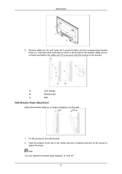
A - LCD Display B - Wall Wall Bracket Angle Adjustment Adjust the bracket angle to -2° before installing it is firmly fixed to the bracket. Wall Bracket C - Then place the ...
A - LCD Display B - Wall Wall Bracket Angle Adjustment Adjust the bracket angle to -2° before installing it is firmly fixed to the bracket. Wall Bracket C - Then place the ...

User Manual
Page 24
Choose one from the following options. Using the DVI (Digital) connector on the video card. • Connect the DVI Cable to the monitor. Connections Connecting a Computer There are several ways to connect the computer to the [DVI IN] port on the back of your LCD Display and the DVI port on the computer. 18 Using the D-sub (Analog) connector on the video card. • Connect the D-sub to the 15-pin, [RGB IN] port on the back of your LCD Display and the 15 pin D-sub Port on the computer.
Choose one from the following options. Using the DVI (Digital) connector on the video card. • Connect the DVI Cable to the monitor. Connections Connecting a Computer There are several ways to connect the computer to the [DVI IN] port on the back of your LCD Display and the DVI port on the computer. 18 Using the D-sub (Analog) connector on the video card. • Connect the D-sub to the 15-pin, [RGB IN] port on the back of your LCD Display and the 15 pin D-sub Port on the computer.

User Manual
Page 25
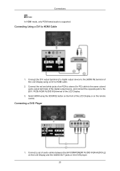
... BNC to the option that follows. Connections Using the HDMI (digital) output on the graphics card. • Connect the [HDMI IN] port on the LCD Display to the PC, ensure that you select HDMI from both the Source List and Edit Name before selecting PC or DVI device so that normal...
... BNC to the option that follows. Connections Using the HDMI (digital) output on the graphics card. • Connect the [HDMI IN] port on the LCD Display to the PC, ensure that you select HDMI from both the Source List and Edit Name before selecting PC or DVI device so that normal...

User Manual
Page 26
... AV input devices, refer to the [AV IN [VIDEO]] port on the back of the LCD Display. Note • Turn on both your computer and the LCD Display. • Contact a local SAMSUNG Electronics Service Center to buy optional items. Connecting to Other devices • AV input devices such as... DVD players, VCRs or camcorders as well as your LCD Display to the power port on the monitor. 2. Select...
... AV input devices, refer to the [AV IN [VIDEO]] port on the back of the LCD Display. Note • Turn on both your computer and the LCD Display. • Contact a local SAMSUNG Electronics Service Center to buy optional items. Connecting to Other devices • AV input devices such as... DVD players, VCRs or camcorders as well as your LCD Display to the power port on the monitor. 2. Select...

User Manual
Page 27
...to BNC cable. 21 Connect a video cable between the AUDIO OUTPUT jacks on the camcorder and the [AV/COMPONENT AUDIO IN [R-AUDIO-L]] on the LCD Display . 2. Connect the [BNC/COMPONENT IN [R/Y, G/PB, B/PR]] ports on the monitor to the BNC port on the external device using the SOURCE ...cable 1. Select AV for the Camcorder connection using the BNC to a Camcorder Connections 1. Connecting the BNC to connect a set of the LCD Display or on the LCD Display . 3. Connect a set of the camcorder. Locate the AV output jacks on the side or back of two cables. Note The audio-...
...to BNC cable. 21 Connect a video cable between the AUDIO OUTPUT jacks on the camcorder and the [AV/COMPONENT AUDIO IN [R-AUDIO-L]] on the LCD Display . 2. Connect the [BNC/COMPONENT IN [R/Y, G/PB, B/PR]] ports on the monitor to the BNC port on the external device using the SOURCE ...cable 1. Select AV for the Camcorder connection using the BNC to a Camcorder Connections 1. Connecting the BNC to connect a set of the LCD Display or on the LCD Display . 3. Connect a set of the camcorder. Locate the AV output jacks on the side or back of two cables. Note The audio-...

User Manual
Page 28
... not support HDCP. Select HDMI using the SOURCE button on the front of the LCD Display using a stereo cable. 3. Connect input devices such as a Blu-Ray/DVD player to the [HDMI IN] terminal of the LCD Display or on another monitor using an HDMI cable. 2. Connecting Using a HDMI Cable 1. Connect... between the [AUDIO OUT] port on the LCD Display and the audio input port on another monitor using a DVI cable. 2. Select DVI ...
... not support HDCP. Select HDMI using the SOURCE button on the front of the LCD Display using a stereo cable. 3. Connect input devices such as a Blu-Ray/DVD player to the [HDMI IN] terminal of the LCD Display or on another monitor using an HDMI cable. 2. Connecting Using a HDMI Cable 1. Connect... between the [AUDIO OUT] port on the LCD Display and the audio input port on another monitor using a DVI cable. 2. Select DVI ...
User Manual
Page 29
... /HDMI AUDIO IN] terminal of audio cables between the [AV/COMPONENT AUDIO IN [R-AUDIO-L]] on the LCD Display and the AUDIO OUT jacks on the remote control. Connect the red and white jacks of an RCA to ...stereo (for PC) cable to the same colored audio output terminals of the LCD Display or on the DVD player. 23 Connections Note In HDMI mode, only PCM format audio is supported. Connect...terminal of a digital output device to the [HDMI IN] terminal of the LCD Display using the SOURCE button on the front of the digital output device, and connect the opposite jack to HDMI ...
... /HDMI AUDIO IN] terminal of audio cables between the [AV/COMPONENT AUDIO IN [R-AUDIO-L]] on the LCD Display and the AUDIO OUT jacks on the remote control. Connect the red and white jacks of an RCA to ...stereo (for PC) cable to the same colored audio output terminals of the LCD Display or on the DVD player. 23 Connections Note In HDMI mode, only PCM format audio is supported. Connect...terminal of a digital output device to the [HDMI IN] terminal of the LCD Display using the SOURCE button on the front of the digital output device, and connect the opposite jack to HDMI ...

User Manual
Page 30
...Connecting a DTV Set Top (Cable/Satellite) Box 1. Connect a set of audio cables between the [BNC/COMPONENT IN [R/Y, G/PB, B/PR]] port on the LCD Display and the PR, Y, PB jacks on the remote control. • Then, start the DVD Player with a DVD disc inserted. • A component cable is optional.... • For an explanation of the LCD Display or on the Set Top Box. 2. Connections 2. Note • Select Component for the connection to a DVD player using the SOURCE button on the front...
...Connecting a DTV Set Top (Cable/Satellite) Box 1. Connect a set of audio cables between the [BNC/COMPONENT IN [R/Y, G/PB, B/PR]] port on the LCD Display and the PR, Y, PB jacks on the remote control. • Then, start the DVD Player with a DVD disc inserted. • A component cable is optional.... • For an explanation of the LCD Display or on the Set Top Box. 2. Connections 2. Note • Select Component for the connection to a DVD player using the SOURCE button on the front...

User Manual
Page 31
Connections Connecting to an Audio System 1. Connect a set of audio cables between the AUX L, R jacks on the AUDIO SYSTEM and [AUDIO OUT] on LCD Display. 25
Connections Connecting to an Audio System 1. Connect a set of audio cables between the AUX L, R jacks on the AUDIO SYSTEM and [AUDIO OUT] on LCD Display. 25


