Operation Manual
Page 2
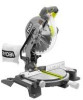
... OF CONTENTS I Introduction and Product Specifications ...2 I Rules for Safe Operation ...3-6 I Glossary of Terms ...6 I Unpacking and Tools Needed ...7 I Loose Parts ...8 I Features ...9-11 I Assembly ...12-14 I Adjustments ...15-18 I Operation ...18-25 I Maintenance ...26 I Parts Ordering/Service ...28 INTRODUCTION Your saw making cutting operations more pleasant and enjoyable. Always wear eye protection which can...
... OF CONTENTS I Introduction and Product Specifications ...2 I Rules for Safe Operation ...3-6 I Glossary of Terms ...6 I Unpacking and Tools Needed ...7 I Loose Parts ...8 I Features ...9-11 I Assembly ...12-14 I Adjustments ...15-18 I Operation ...18-25 I Maintenance ...26 I Parts Ordering/Service ...28 INTRODUCTION Your saw making cutting operations more pleasant and enjoyable. Always wear eye protection which can...
Operation Manual
Page 3
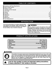
... of information or instructions vital to the operation or maintenance of safety symbols is to attract your attention to your nearest RYOBI AUTHORIZED SERVICE CENTER for complete safety, assembly, operating and maintenance, and repair information. SYMBOL MEANING • Do not ...all instructions, safety rules, etc., contained in electric power tools, which , if not avoided, may use only identical Ryobi replacement parts. All exposed metal parts are not substitutes for continuing safe operation, and instructing others who may result in serious personal injury. Read the operator...
... of information or instructions vital to the operation or maintenance of safety symbols is to attract your attention to your nearest RYOBI AUTHORIZED SERVICE CENTER for complete safety, assembly, operating and maintenance, and repair information. SYMBOL MEANING • Do not ...all instructions, safety rules, etc., contained in electric power tools, which , if not avoided, may use only identical Ryobi replacement parts. All exposed metal parts are not substitutes for continuing safe operation, and instructing others who may result in serious personal injury. Read the operator...
Operation Manual
Page 4
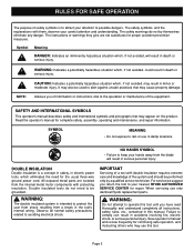
...GUARDS IN PLACE and in the habit - Use the right blade size, style and cutting speed for alignment of moving parts, binding of moving parts, breakage of parts, mounting and any reason. Sharp blades minimize stalling and kickback. I DO NOT USE IN DANGEROUS ENVIRONMENTS. Always turn power...in use, before servicing, or when changing attachments, all guards are defective or incorrect. Do not use power tools near gasoline or other part that is off . I USE RECOMMENDED ACCESSORIES. A wire gage size (A.W.G.) of at all labels affixed to rain. Nonslip footwear is unintentionally...
...GUARDS IN PLACE and in the habit - Use the right blade size, style and cutting speed for alignment of moving parts, binding of moving parts, breakage of parts, mounting and any reason. Sharp blades minimize stalling and kickback. I DO NOT USE IN DANGEROUS ENVIRONMENTS. Always turn power...in use, before servicing, or when changing attachments, all guards are defective or incorrect. Do not use power tools near gasoline or other part that is off . I USE RECOMMENDED ACCESSORIES. A wire gage size (A.W.G.) of at all labels affixed to rain. Nonslip footwear is unintentionally...
Operation Manual
Page 5
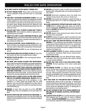
store cords indoors while not in use only identical Ryobi replacement parts. I BEFORE MAKING A CUT, be cut on the miter table and...cause a careless mistake. I NEVER USE THIS TOOL IN AN EXPLOSIVE ATMOSPHERE. I NEVER stand or have any part of the workpiece in line with the blade touching the workpiece. I NEVER hand hold onto or bind the free... against the fence as a backstop. Use extension cords with an electrical rating not less than the other moving parts during use a clean cloth when cleaning. All repairs, whether electrical or mechanical, should any way, or should...
store cords indoors while not in use only identical Ryobi replacement parts. I BEFORE MAKING A CUT, be cut on the miter table and...cause a careless mistake. I NEVER USE THIS TOOL IN AN EXPLOSIVE ATMOSPHERE. I NEVER stand or have any part of the workpiece in line with the blade touching the workpiece. I NEVER hand hold onto or bind the free... against the fence as a backstop. Use extension cords with an electrical rating not less than the other moving parts during use a clean cloth when cleaning. All repairs, whether electrical or mechanical, should any way, or should...

Operation Manual
Page 7
...the saw is heavy. See Figure 1. To avoid back injury, get help when needed for checking adjustments of the tie wrap. If any parts are missing, do not attempt to do not operate this saw arm to make sure no breakage or damage has occurred during shipping. TOOLS ...NEEDED The following tools (not included) are replaced. I Examine all loose parts from the carton by the handle. Call 1-800-525-2579 for installing the blade: 12 mm COMBINATION WRENCH 6 mm HEX KEY FRAMING SQUARE COMBINATION...
...the saw is heavy. See Figure 1. To avoid back injury, get help when needed for checking adjustments of the tie wrap. If any parts are missing, do not attempt to do not operate this saw arm to make sure no breakage or damage has occurred during shipping. TOOLS ...NEEDED The following tools (not included) are replaced. I Examine all loose parts from the carton by the handle. Call 1-800-525-2579 for installing the blade: 12 mm COMBINATION WRENCH 6 mm HEX KEY FRAMING SQUARE COMBINATION...

Operation Manual
Page 8
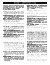
Page 8 LOOSE PARTS LIST The following items are included with your Compound Miter Saw: I 10 in. (254 mm) Saw Blade I Work Clamp I Miter Lock Handle I Blade Wrench I Dust Bag I Operator's Manual I Dust Guide I Warranty Registration Card DUST BAG BLADE WRENCH SAW BLADE DUST GUIDE 5 MITER LOCK HANDLE WORK CLAMP Fig. 1 WARNING: The use of attachments or accessories not listed might be hazardous and could cause serious personal injury.
Page 8 LOOSE PARTS LIST The following items are included with your Compound Miter Saw: I 10 in. (254 mm) Saw Blade I Work Clamp I Miter Lock Handle I Blade Wrench I Dust Bag I Operator's Manual I Dust Guide I Warranty Registration Card DUST BAG BLADE WRENCH SAW BLADE DUST GUIDE 5 MITER LOCK HANDLE WORK CLAMP Fig. 1 WARNING: The use of attachments or accessories not listed might be hazardous and could cause serious personal injury.

Operation Manual
Page 12
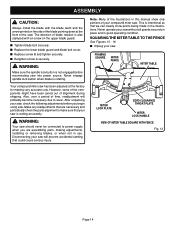
..., install the clamp on the end of the miter lock handle into the threaded hole in use. Always make sure all fasteners are assembling parts, making the cut. This is no interference with the blade guard prior to reduce the risk of serious personal injury. WARNING: When using ...to beginning any clamp with the operation of the blade guard assembly. Turn the guide so that could cause possible serious personal injury, assemble all parts, make sure all adjustments are complete, and make sure there is very helpful when cutting compound miters. To install it, remove dust guide ...
..., install the clamp on the end of the miter lock handle into the threaded hole in use. Always make sure all fasteners are assembling parts, making the cut. This is no interference with the blade guard prior to reduce the risk of serious personal injury. WARNING: When using ...to beginning any clamp with the operation of the blade guard assembly. Turn the guide so that could cause possible serious personal injury, assemble all parts, make sure all adjustments are complete, and make sure there is very helpful when cutting compound miters. To install it, remove dust guide ...
Operation Manual
Page 14
...for making adjustments, installing or removing blades, or when not in the illustrations. This is not engaged before you are necessary and periodically check the parts alignment to wear. ASSEMBLY CAUTION: Always install the blade with an arrow on the side of alignment during shipping. I Replace the lower blade ...blade bolt cover. Note: Many of the illustrations in this manual show points being made in use. Make any readjustments that are assembling parts, making very accurate cuts. The direction of blade rotation is rotating. I Tighten blade bolt securely.
...for making adjustments, installing or removing blades, or when not in the illustrations. This is not engaged before you are necessary and periodically check the parts alignment to wear. ASSEMBLY CAUTION: Always install the blade with an arrow on the side of alignment during shipping. I Replace the lower blade ...blade bolt cover. Note: Many of the illustrations in this manual show points being made in use. Make any readjustments that are assembling parts, making very accurate cuts. The direction of blade rotation is rotating. I Tighten blade bolt securely.

Operation Manual
Page 15
... Lay a framing square flat on the miter table. WARNING: Failure to hold the saw blade. Note: Make sure that the square contacts the flat part of the square beside the zero clearance throat plate in transport position. I Release the miter lock plate and securely tighten the miter lock handle. I ...the miter table until the pointer on the miter table. I Loosen the miter lock handle approximately one leg of the square against the flat part of the square and the zero clearance throat plate in the miter table should be parallel as shown in figure 15. I Retighten the ...
... Lay a framing square flat on the miter table. WARNING: Failure to hold the saw blade. Note: Make sure that the square contacts the flat part of the square beside the zero clearance throat plate in transport position. I Release the miter lock plate and securely tighten the miter lock handle. I ...the miter table until the pointer on the miter table. I Loosen the miter lock handle approximately one leg of the square against the flat part of the square and the zero clearance throat plate in the miter table should be parallel as shown in figure 15. I Retighten the ...

Operation Manual
Page 17
...in figures 22 and 23, adjustments are needed. I Unplug your saw could result in transport position. Note: Make sure that the square contacts the flat part of the saw . I Loosen bevel lock knob and set 90° to -table alignment at both 0° and 45° angles. I If... PLATE VIEW OF BLADE NOT SQUARE WITH MITER TABLE, ADJUSTMENTS ARE REQUIRED Fig. 23 I Place a combination square against the miter table and the flat part of the square and the saw blade. See Figure 20. I Adjust positive stop adjustment screw. I Retighten bevel lock knob. ADJUSTMENTS SQUARING THE BLADE...
...in figures 22 and 23, adjustments are needed. I Unplug your saw could result in transport position. Note: Make sure that the square contacts the flat part of the saw . I Loosen bevel lock knob and set 90° to -table alignment at both 0° and 45° angles. I If... PLATE VIEW OF BLADE NOT SQUARE WITH MITER TABLE, ADJUSTMENTS ARE REQUIRED Fig. 23 I Place a combination square against the miter table and the flat part of the square and the saw blade. See Figure 20. I Adjust positive stop adjustment screw. I Retighten bevel lock knob. ADJUSTMENTS SQUARING THE BLADE...

Operation Manual
Page 26
...bearings, brushes, commutators, etc. Use clean cloths to damage from these materials it will cause some loss of any use only identical Ryobi replacement parts. come in serious injury. Consequently, it is not recommended that this tool be damaged by a qualified service technician at any time ...that it is extremely important that is recommended for an extension cord 25 feet or less in length. WARNING: Do not at a Ryobi Authorized Service Center to prevent tool overheating, use . LUBRICATION All of the bearings in serious personal injury. CAUTION: Check extension cords before...
...bearings, brushes, commutators, etc. Use clean cloths to damage from these materials it will cause some loss of any use only identical Ryobi replacement parts. come in serious injury. Consequently, it is not recommended that this tool be damaged by a qualified service technician at any time ...that it is extremely important that is recommended for an extension cord 25 feet or less in length. WARNING: Do not at a Ryobi Authorized Service Center to prevent tool overheating, use . LUBRICATION All of the bearings in serious personal injury. CAUTION: Check extension cords before...
Operation Manual
Page 28
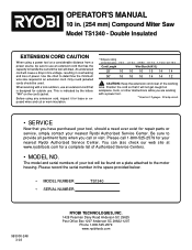
... using a power tool at www.ryobitools.com for repair parts or service, simply contact your nearest Ryobi Authorized Service Center. You can also check our web site... 10 in the space provided below. • MODEL NUMBER • SERIAL NUMBER TS1340 983000-248 3-03 RYOBI TECHNOLOGIES, INC. 1428 Pearman Dairy Road Anderson SC 29625 Post Office Box 1207 Anderson SC 29622-1207 Phone .... Please call or visit. Use the chart to the motor housing. This is designed for your nearest Ryobi Authorized Service Center. When working with a power tool. **Used on 12 gauge - 20 amp circuit....
... using a power tool at www.ryobitools.com for repair parts or service, simply contact your nearest Ryobi Authorized Service Center. You can also check our web site... 10 in the space provided below. • MODEL NUMBER • SERIAL NUMBER TS1340 983000-248 3-03 RYOBI TECHNOLOGIES, INC. 1428 Pearman Dairy Road Anderson SC 29625 Post Office Box 1207 Anderson SC 29622-1207 Phone .... Please call or visit. Use the chart to the motor housing. This is designed for your nearest Ryobi Authorized Service Center. When working with a power tool. **Used on 12 gauge - 20 amp circuit....
Parts Diagram
Page 3
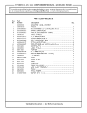
... 580114000 14 A35030410018 15 A10003040107 16 518105400 17 A49001020056 18 580119000 19 580117000 20 580120000 21 511104000 22 518A08130 23 512106000 24 589027202 25 A16003040083 PARTS LIST - May Be Purchased Locally 3 FIGURE A Description Qty. Always mention the model number in . (254 mm) COMPOUND MITER SAW - BASE AND TABLE ASSEMBLY FENCE... TABLE 1 TABLE INSERT 1 * SCREW (M4 X 8 mm 4 * Standard Hardware Item - TS1340 The model number will be found on a plate attached to the motor housing. RYOBI 10 in all correspondence regarding your Compound Miter Saw or when ordering repair...
... 580114000 14 A35030410018 15 A10003040107 16 518105400 17 A49001020056 18 580119000 19 580117000 20 580120000 21 511104000 22 518A08130 23 512106000 24 589027202 25 A16003040083 PARTS LIST - May Be Purchased Locally 3 FIGURE A Description Qty. Always mention the model number in . (254 mm) COMPOUND MITER SAW - BASE AND TABLE ASSEMBLY FENCE... TABLE 1 TABLE INSERT 1 * SCREW (M4 X 8 mm 4 * Standard Hardware Item - TS1340 The model number will be found on a plate attached to the motor housing. RYOBI 10 in all correspondence regarding your Compound Miter Saw or when ordering repair...
Parts Diagram
Page 5
Key Part No. RYOBI 10 in all correspondence regarding your Compound Miter Saw or when ordering repair parts. Always mention the model number in . (254 mm) COMPOUND MITER SAW - TS1340 The model number will be found on a plate attached to the... A30003010007 30 A18003100206 31 A30003012194 32 A36031226023 33 A46000150008 34 A50060020056 35 A63020000320 36 586004800 37 588026106 38 A47000040006 39 588027005 40 588A05043 41 588031004 PARTS LIST - MODEL NO. MOTOR ASSEMBLY CORD HOLDER 1 * PANCROSS SCREW (M5 X 30 mm 4 MOTOR HOUSING 1 * FIXED SCREW (M5 X 5 mm 2 * FIXED SCREW (M5 X 6 mm 2 ...
Key Part No. RYOBI 10 in all correspondence regarding your Compound Miter Saw or when ordering repair parts. Always mention the model number in . (254 mm) COMPOUND MITER SAW - TS1340 The model number will be found on a plate attached to the... A30003010007 30 A18003100206 31 A30003012194 32 A36031226023 33 A46000150008 34 A50060020056 35 A63020000320 36 586004800 37 588026106 38 A47000040006 39 588027005 40 588A05043 41 588031004 PARTS LIST - MODEL NO. MOTOR ASSEMBLY CORD HOLDER 1 * PANCROSS SCREW (M5 X 30 mm 4 MOTOR HOUSING 1 * FIXED SCREW (M5 X 5 mm 2 * FIXED SCREW (M5 X 6 mm 2 ...

Parts Diagram
Page 6
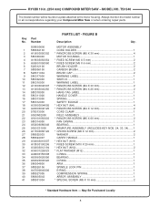
RYOBI 10 in all correspondence regarding your Compound Miter Saw or when ordering repair parts. Key Part No. FIGURE B CONTINUED Description Qty. MODEL NO. TS1340 The model number will be found on a plate attached to the motor housing. ... A10003050105 70 589034005 71 A35030519105 72 A31703004006 73 A31703005005 74 589032207 75 A10003040152 76 581410003 77 580514000 78 A07910520000 79 A07810622000 80 A07910820000 81 580310000 PARTS LIST - STOP PIN CAP 1 O-RING 1 STOP PIN 1 * PANCROSS SCREW (M4 X 16 mm 1 RUBBER SLEEVE 1 E-RING 1 LOWER GUARD ASSEMBLY 1 RETAINING SPRING HOLDER 1 ...
RYOBI 10 in all correspondence regarding your Compound Miter Saw or when ordering repair parts. Key Part No. FIGURE B CONTINUED Description Qty. MODEL NO. TS1340 The model number will be found on a plate attached to the motor housing. ... A10003050105 70 589034005 71 A35030519105 72 A31703004006 73 A31703005005 74 589032207 75 A10003040152 76 581410003 77 580514000 78 A07910520000 79 A07810622000 80 A07910820000 81 580310000 PARTS LIST - STOP PIN CAP 1 O-RING 1 STOP PIN 1 * PANCROSS SCREW (M4 X 16 mm 1 RUBBER SLEEVE 1 E-RING 1 LOWER GUARD ASSEMBLY 1 RETAINING SPRING HOLDER 1 ...
Parts Diagram
Page 8
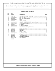
... SHAFT 1 * FLAT WASHER (M10 1 HANDLE 1 TENSION SPRING 1 OPERATOR'S MANUAL REPAIR SHEET * Standard Hardware Item - May Be Purchased Locally 8 Key Part No. Number 1 511D04020 2 A30003006003 3 578206000 4 A49001020056 5 580202000 6 A07003100256 7 A36031018255 8 578203007 9 A35030410018 10 A10003040107 11 578205106 12 588058103 13 589011308... 14 589010200 15 A35031025153 16 589012100 17 580319000 983000-248 983000-248R 1-16-04 PARTS LIST - TS1340 The model number will be found on a plate attached to the motor housing. Always mention the ...
... SHAFT 1 * FLAT WASHER (M10 1 HANDLE 1 TENSION SPRING 1 OPERATOR'S MANUAL REPAIR SHEET * Standard Hardware Item - May Be Purchased Locally 8 Key Part No. Number 1 511D04020 2 A30003006003 3 578206000 4 A49001020056 5 580202000 6 A07003100256 7 A36031018255 8 578203007 9 A35030410018 10 A10003040107 11 578205106 12 588058103 13 589011308... 14 589010200 15 A35031025153 16 589012100 17 580319000 983000-248 983000-248R 1-16-04 PARTS LIST - TS1340 The model number will be found on a plate attached to the motor housing. Always mention the ...


