Operation Manual
Page 2
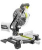
... the operator's manual. Always wear eye protection which can result in the design of this symbol to the safety rules, including Dangers, Warnings, and Cautions. TABLE OF CONTENTS I Introduction and Product Specifications ...2 I Rules for Safe Operation ...3-6 I Glossary of Terms ...6 I Unpacking and Tools Needed ...7 I Loose Parts ...8 I Features ...9-11 I Assembly ...12-14 I Adjustments ...15-18 I Operation ...18-25 I Maintenance ...26 I Parts Ordering/Service ...28 INTRODUCTION Your saw making cutting operations...
... the operator's manual. Always wear eye protection which can result in the design of this symbol to the safety rules, including Dangers, Warnings, and Cautions. TABLE OF CONTENTS I Introduction and Product Specifications ...2 I Rules for Safe Operation ...3-6 I Glossary of Terms ...6 I Unpacking and Tools Needed ...7 I Loose Parts ...8 I Features ...9-11 I Assembly ...12-14 I Adjustments ...15-18 I Operation ...18-25 I Maintenance ...26 I Parts Ordering/Service ...28 INTRODUCTION Your saw making cutting operations...
Operation Manual
Page 3
... situation which eliminates the need to be used to comply can result in the tool's internal wiring. Read the operator's manual for continuing safe operation, and instructing others who may also be grounded. Failure to alert against unsafe practices that may result in this tool. Save operator's manual and review frequently for complete safety, assembly, operating and maintenance, and repair information. IMPORTANT Servicing of a tool with double insulation requires...
... situation which eliminates the need to be used to comply can result in the tool's internal wiring. Read the operator's manual for continuing safe operation, and instructing others who may also be grounded. Failure to alert against unsafe practices that may result in this tool. Save operator's manual and review frequently for complete safety, assembly, operating and maintenance, and repair information. IMPORTANT Servicing of a tool with double insulation requires...
Operation Manual
Page 4
... fine particles. Follow instructions for material and type of power and overheating. I DO NOT USE IN DANGEROUS ENVIRONMENTS. READ ALL INSTRUCTIONS I KEEP GUARDS IN PLACE and in operation. Get in loss of cut. Before using your miter saw to rain. Use the right blade size, style and cutting speed for lubricating and changing accessories. before each use power tools near gasoline or other part that hex keys and adjusting wrenches are NOT safety glasses. If in...
... fine particles. Follow instructions for material and type of power and overheating. I DO NOT USE IN DANGEROUS ENVIRONMENTS. READ ALL INSTRUCTIONS I KEEP GUARDS IN PLACE and in operation. Get in loss of cut. Before using your miter saw to rain. Use the right blade size, style and cutting speed for lubricating and changing accessories. before each use power tools near gasoline or other part that hex keys and adjusting wrenches are NOT safety glasses. If in...
Operation Manual
Page 5
... serious injury. I DO NOT USE TOOL IF SWITCH DOES NOT TURN IT ON AND OFF. I USE ONLY OUTDOOR EXTENSION CORDS. I REPLACEMENT PARTS. Never use with the blade touching the workpiece. Never start the saw blade to stop rotating before starting cut. This could cause the saw arm (bevel function) by securely tightening the bevel lock knob. I KEEP TOOL DRY, CLEAN, AND FREE FROM OIL AND GREASE. Use of the blade. Do not change the plug in a polarized outlet...
... serious injury. I DO NOT USE TOOL IF SWITCH DOES NOT TURN IT ON AND OFF. I USE ONLY OUTDOOR EXTENSION CORDS. I REPLACEMENT PARTS. Never use with the blade touching the workpiece. Never start the saw blade to stop rotating before starting cut. This could cause the saw arm (bevel function) by securely tightening the bevel lock knob. I KEEP TOOL DRY, CLEAN, AND FREE FROM OIL AND GREASE. Use of the blade. Do not change the plug in a polarized outlet...

Operation Manual
Page 6
... or changing settings. Do not rush. WARNING: Some dust created by power sanding, sawing, grinding, drilling, and other construction activities contains chemicals known to the fence. Usually associated with approved safety equipment, such as faces, ends, and edges. When you loan someone this tool, loan them to the miter table. NEVER leave the saw blade tooth is being placed inadvertently in a well ventilated area and work clamp...
... or changing settings. Do not rush. WARNING: Some dust created by power sanding, sawing, grinding, drilling, and other construction activities contains chemicals known to the fence. Usually associated with approved safety equipment, such as faces, ends, and edges. When you loan someone this tool, loan them to the miter table. NEVER leave the saw blade tooth is being placed inadvertently in a well ventilated area and work clamp...

Operation Manual
Page 7
... serious personal injury. Although small, this tool until the missing parts are obtained and are missing, do so could result in the power cord, or turn the switch on top of the tie wrap. WARNING: If any parts are installed correctly. I Carefully lift saw is heavy. UNPACKING Your Compound Miter Saw has been shipped completely assembled except for the blade, miter lock handle, dust guide or dust bag, table extensions, work surface.
... serious personal injury. Although small, this tool until the missing parts are obtained and are missing, do so could result in the power cord, or turn the switch on top of the tie wrap. WARNING: If any parts are installed correctly. I Carefully lift saw is heavy. UNPACKING Your Compound Miter Saw has been shipped completely assembled except for the blade, miter lock handle, dust guide or dust bag, table extensions, work surface.

Operation Manual
Page 8
Page 8 LOOSE PARTS LIST The following items are included with your Compound Miter Saw: I 10 in. (254 mm) Saw Blade I Work Clamp I Miter Lock Handle I Blade Wrench I Dust Bag I Operator's Manual I Dust Guide I Warranty Registration Card DUST BAG BLADE WRENCH SAW BLADE DUST GUIDE 5 MITER LOCK HANDLE WORK CLAMP Fig. 1 WARNING: The use of attachments or accessories not listed might be hazardous and could cause serious personal injury.
Page 8 LOOSE PARTS LIST The following items are included with your Compound Miter Saw: I 10 in. (254 mm) Saw Blade I Work Clamp I Miter Lock Handle I Blade Wrench I Dust Bag I Operator's Manual I Dust Guide I Warranty Registration Card DUST BAG BLADE WRENCH SAW BLADE DUST GUIDE 5 MITER LOCK HANDLE WORK CLAMP Fig. 1 WARNING: The use of attachments or accessories not listed might be hazardous and could cause serious personal injury.

Operation Manual
Page 9
... the accessory blades available from your saw to handle tough cutting jobs. It is set at 45°: Maximum dimensional lumber size: 2 x 4 UPPER BLADE GUARD DUST GUIDE SAW ARM SWITCH TRIGGER LOWER BLADE GUARD BEVEL LOCK KNOB BEVEL SCALE MITER FENCE MITER TABLE "NO HANDS ZONE" LABEL "NO HANDS ZONE" BOUNDARY LINE MITER SCALE MITER TABLE FRAME CONTROL ARM MITER LOCK HANDLE POSITIVE STOP(S) ZERO CLEARANCE THROAT PLATE MITER LOCK PLATE Page 9 Fig. 2 WARNING: Do not allow familiarity with your nearest dealer. BLADE A 10 in. (254 mm) saw blade is...
... the accessory blades available from your saw to handle tough cutting jobs. It is set at 45°: Maximum dimensional lumber size: 2 x 4 UPPER BLADE GUARD DUST GUIDE SAW ARM SWITCH TRIGGER LOWER BLADE GUARD BEVEL LOCK KNOB BEVEL SCALE MITER FENCE MITER TABLE "NO HANDS ZONE" LABEL "NO HANDS ZONE" BOUNDARY LINE MITER SCALE MITER TABLE FRAME CONTROL ARM MITER LOCK HANDLE POSITIVE STOP(S) ZERO CLEARANCE THROAT PLATE MITER LOCK PLATE Page 9 Fig. 2 WARNING: Do not allow familiarity with your nearest dealer. BLADE A 10 in. (254 mm) saw blade is...

Operation Manual
Page 10
... top of your saw at desired miter angles. To transport, turn off position. The miter lock handle securely locks your compound miter saw from rotating. SWITCH TRIGGER SWITCH TRIGGER SPINDLE LOCK BUTTON Fig. 4 SAW ARM LOCK PIN CARRYING HANDLE PADLOCK Fig. 5 MITER LOCK HANDLE SAW ARM LOCKED IN DOWN POSITION TRIGGER LOCK See Figure 5. To lock the switch, install a padlock (not included) through the hole in . (7 mm) diameter may be used. FEATURES BLADE WRENCH / STORAGE AREA See Figure 2. Use the hex key end when installing or removing blade and the...
... top of your saw at desired miter angles. To transport, turn off position. The miter lock handle securely locks your compound miter saw from rotating. SWITCH TRIGGER SWITCH TRIGGER SPINDLE LOCK BUTTON Fig. 4 SAW ARM LOCK PIN CARRYING HANDLE PADLOCK Fig. 5 MITER LOCK HANDLE SAW ARM LOCKED IN DOWN POSITION TRIGGER LOCK See Figure 5. To lock the switch, install a padlock (not included) through the hole in . (7 mm) diameter may be used. FEATURES BLADE WRENCH / STORAGE AREA See Figure 2. Use the hex key end when installing or removing blade and the...

Operation Manual
Page 11
... face shield when needed. The 22-1/2° and 45° positive stops have been provided in . (457 mm x 610 mm) workbench. ELECTRIC BRAKE An electric brake has been provided to quickly stop adjustment screws have been provided on your compound miter saw has been provided to modify this purpose. WARNING: The operation of power and the motor will overheat. BEVEL LOCK KNOB The bevel lock knob securely locks your workpiece...
... face shield when needed. The 22-1/2° and 45° positive stops have been provided in . (457 mm x 610 mm) workbench. ELECTRIC BRAKE An electric brake has been provided to quickly stop adjustment screws have been provided on your compound miter saw has been provided to modify this purpose. WARNING: The operation of power and the motor will overheat. BEVEL LOCK KNOB The bevel lock knob securely locks your workpiece...

Operation Manual
Page 12
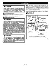
... these directions to tighten. Turn clockwise to install the work clamp to power supply. Turn the guide so that could cause possible serious personal injury, assemble all parts, make sure all fasteners are secure before connecting saw . Depending on the cutting operation and the size of the workpiece, it in or out as the stop block, install the clamp on the same side as needed. Failure to making adjustments, installing or removing blades...
... these directions to tighten. Turn clockwise to install the work clamp to power supply. Turn the guide so that could cause possible serious personal injury, assemble all parts, make sure all fasteners are secure before connecting saw . Depending on the cutting operation and the size of the workpiece, it in or out as the stop block, install the clamp on the same side as needed. Failure to making adjustments, installing or removing blades...

Operation Manual
Page 13
... figure 11. I Fit saw arm. I Remove outer blade washer. I Depress spindle lock button and replace blade bolt. I Replace outer blade washer. Note: The blade bolt has left hand threads. I Using the wrench provided, loosen and remove the blade bolt. I Raise saw blade inside lower blade guard and onto spindle. Failure to tighten. I Loosen screw A on the spindle. Larger blades will prevent the blade bolt from securing the blade on spindle. Either of oil onto inner blade washer and outer blade washer where they contact the...
... figure 11. I Fit saw arm. I Remove outer blade washer. I Depress spindle lock button and replace blade bolt. I Replace outer blade washer. Note: The blade bolt has left hand threads. I Using the wrench provided, loosen and remove the blade bolt. I Raise saw blade inside lower blade guard and onto spindle. Failure to tighten. I Loosen screw A on the spindle. Larger blades will prevent the blade bolt from securing the blade on spindle. Either of oil onto inner blade washer and outer blade washer where they contact the...
Operation Manual
Page 14
... 31.6 30 MITER LOCK PLATE ZERO CLEARANCE THROAT PLATE MITER LOCK HANDLE VIEW OF MITER TABLE SQUARE WITH FENCE Fig. 13 Page 14 After unpacking your saw without all guards securely in place and in use. WARNING: Your saw into power source. I Replace the lower blade guard and blade bolt cover. Note: Many of the blade pointing down at the factory for making adjustments, installing or removing blades, or when not in good operating condition. Also...
... 31.6 30 MITER LOCK PLATE ZERO CLEARANCE THROAT PLATE MITER LOCK HANDLE VIEW OF MITER TABLE SQUARE WITH FENCE Fig. 13 Page 14 After unpacking your saw without all guards securely in place and in use. WARNING: Your saw into power source. I Replace the lower blade guard and blade bolt cover. Note: Many of the blade pointing down at the factory for making adjustments, installing or removing blades, or when not in good operating condition. Also...

Operation Manual
Page 15
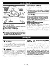
... shown in the miter table. The edge of saw . I Lay a framing square flat on the miter table. I Loosen the miter lock handle approximately one leg of the saw could result in accidental starting causing possible serious personal injury. I Using the blade wrench provided, loosen the socket head screws securing the fence. I Depress the miter lock plate and rotate the miter table until the framing square and zero clearance throat plate are needed. Adjust the fence left or right...
... shown in the miter table. The edge of saw . I Lay a framing square flat on the miter table. I Loosen the miter lock handle approximately one leg of the saw could result in accidental starting causing possible serious personal injury. I Using the blade wrench provided, loosen the socket head screws securing the fence. I Depress the miter lock plate and rotate the miter table until the framing square and zero clearance throat plate are needed. Adjust the fence left or right...

Operation Manual
Page 17
... reset them to miter table). Also loosen bevel lock knob. I Rotate the blade by hand and check the blade-to bring saw blade angles away from the square as shown in figures 22 and 23, adjustments are needed. BEVEL LOCK KNOB MITER FENCE BLADE COMBINATION SQUARE MITER TABLE MITER LOCK HANDLE MITER LOCK PLATE CORRECT VIEW OF BLADE SQUARE WITH MITER TABLE Fig. 21 COMBINATION SQUARE MITER TABLE MITER LOCK PLATE VIEW OF BLADE NOT SQUARE WITH MITER TABLE, ADJUSTMENTS ARE REQUIRED Fig. 22 BEVEL LOCK KNOB MITER FENCE BLADE COMBINATION SQUARE MITER TABLE MITER LOCK PLATE...
... reset them to miter table). Also loosen bevel lock knob. I Rotate the blade by hand and check the blade-to bring saw blade angles away from the square as shown in figures 22 and 23, adjustments are needed. BEVEL LOCK KNOB MITER FENCE BLADE COMBINATION SQUARE MITER TABLE MITER LOCK HANDLE MITER LOCK PLATE CORRECT VIEW OF BLADE SQUARE WITH MITER TABLE Fig. 21 COMBINATION SQUARE MITER TABLE MITER LOCK PLATE VIEW OF BLADE NOT SQUARE WITH MITER TABLE, ADJUSTMENTS ARE REQUIRED Fig. 22 BEVEL LOCK KNOB MITER FENCE BLADE COMBINATION SQUARE MITER TABLE MITER LOCK PLATE...
Operation Manual
Page 18
... the fence). at 0° miter, turn your Ryobi dealer. To cut as far as it strikes the miter table support during operation of the accessory blades available from 0° to heed this warning can result in serious personal injury. Turn your compound miter saw, you must cut through the throat plate. for the purposes listed below) I Cross cutting wood and plastic. Page 18 LOCK NUT(S) Fig. 24 PIVOT ADJUSTMENTS Note: These adjustments were...
... the fence). at 0° miter, turn your Ryobi dealer. To cut as far as it strikes the miter table support during operation of the accessory blades available from 0° to heed this warning can result in serious personal injury. Turn your compound miter saw, you must cut through the throat plate. for the purposes listed below) I Cross cutting wood and plastic. Page 18 LOCK NUT(S) Fig. 24 PIVOT ADJUSTMENTS Note: These adjustments were...

Operation Manual
Page 19
... COMPOUND MITER SAW WARNING: When using a work clamp or C-clamp to secure your thumb and hold. The workpiece must remain free on the blade at the end of the cut . A crosscut is warped, place the convex side against the fence. TO CROSSCUT WITH YOUR MITER SAW I Press the miter lock plate down with the miter table set at some angle other than zero. I Pull out the lock pin and lift saw table. Rotate the miter lock handle...
... COMPOUND MITER SAW WARNING: When using a work clamp or C-clamp to secure your thumb and hold. The workpiece must remain free on the blade at the end of the cut . A crosscut is warped, place the convex side against the fence. TO CROSSCUT WITH YOUR MITER SAW I Press the miter lock plate down with the miter table set at some angle other than zero. I Pull out the lock pin and lift saw table. Rotate the miter lock handle...
Operation Manual
Page 20
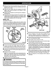
... cutting long pieces of lumber or molding, support the opposite end of the workpiece with zero on the miter scale. I Loosen the bevel lock knob and move the saw blade to the workpiece. Note: You can be set from the miter table. I Press the miter lock plate down with the saw handle firmly then squeeze the switch trigger. See Figure 25. I Grasp the saw table. Wait until the pointer aligns with the blade angled...
... cutting long pieces of lumber or molding, support the opposite end of the workpiece with zero on the miter scale. I Loosen the bevel lock knob and move the saw blade to the workpiece. Note: You can be set from the miter table. I Press the miter lock plate down with the saw handle firmly then squeeze the switch trigger. See Figure 25. I Grasp the saw table. Wait until the pointer aligns with the blade angled...
Operation Manual
Page 21
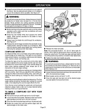
... A COMPOUND CUT WITH YOUR MITER SAW I Release the switch trigger and allow the saw arm to the correct bevel angle. The blade could result in movement of the bevel setting. I Pull out the lock pin and lift saw blade to reach maximum speed. COMPOUND MITER CUT A compound miter cut is a cut is made using a miter angle and a bevel angle at least 3 in scrap material before raising the blade out of the cutting operation just to 45˚. Also, each time you adjust the bevel setting you change...
... A COMPOUND CUT WITH YOUR MITER SAW I Release the switch trigger and allow the saw arm to the correct bevel angle. The blade could result in movement of the bevel setting. I Pull out the lock pin and lift saw blade to reach maximum speed. COMPOUND MITER CUT A compound miter cut is a cut is made using a miter angle and a bevel angle at least 3 in scrap material before raising the blade out of the cutting operation just to 45˚. Also, each time you adjust the bevel setting you change...

Operation Manual
Page 26
... electric tool parts such as bearings, brushes, commutators, etc. It has been found that can damage, weaken or destroy plastic. CAUTION: Check extension cords before each use only identical Ryobi replacement parts. Never use of any other part may create a hazard or cause product damage. If operation is cleaned frequently by a qualified service technician at any fiberglass material, wallboard, spackling compounds, or plaster. EXTENSION CORDS...
... electric tool parts such as bearings, brushes, commutators, etc. It has been found that can damage, weaken or destroy plastic. CAUTION: Check extension cords before each use only identical Ryobi replacement parts. Never use of any other part may create a hazard or cause product damage. If operation is cleaned frequently by a qualified service technician at any fiberglass material, wallboard, spackling compounds, or plaster. EXTENSION CORDS...


