English Manual
Page 4
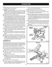
...-grounding conductor to prevent the saw from the rotating blade. Inspect EXTENSION CORDS periodically and replace if damaged. POLARIZED PLUGS. Lock the saw table at a time. If repair or replacement of the saw is too small to be sure all nails from lumber before connecting ...in this tool has a polarized plug (one piece at a time. MAKE SURE THE MITER TABLE AND SAW ARM (BEVEL FUNCTION) ARE LOCKED IN POSITION BEFORE OPERATING YOUR SAW. If it well away from catching the loose end and kicking up. NEVER perform any operation freehand. Watch...
...-grounding conductor to prevent the saw from the rotating blade. Inspect EXTENSION CORDS periodically and replace if damaged. POLARIZED PLUGS. Lock the saw table at a time. If repair or replacement of the saw is too small to be sure all nails from lumber before connecting ...in this tool has a polarized plug (one piece at a time. MAKE SURE THE MITER TABLE AND SAW ARM (BEVEL FUNCTION) ARE LOCKED IN POSITION BEFORE OPERATING YOUR SAW. If it well away from catching the loose end and kicking up. NEVER perform any operation freehand. Watch...
English Manual
Page 10
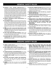
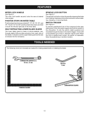
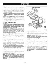
... lumber sizes 2 x 6 Cutting Capacity with Miter at 45°/Bevel 45°: Maximum nominal lumber sizes 2 x 4 blade wrench Upper Blade Guard "D" Handle DUST BAG Bevel Lock Knob Bevel Scale MITER Fence Miter Table BASE Switch Trigger Lower blade guard throat plate "NO HANDS ZONE" LABEL "NO HANDS ZONE" BOUNDARY LINE Miter...
... lumber sizes 2 x 6 Cutting Capacity with Miter at 45°/Bevel 45°: Maximum nominal lumber sizes 2 x 4 blade wrench Upper Blade Guard "D" Handle DUST BAG Bevel Lock Knob Bevel Scale MITER Fence Miter Table BASE Switch Trigger Lower blade guard throat plate "NO HANDS ZONE" LABEL "NO HANDS ZONE" BOUNDARY LINE Miter...
English Manual
Page 11
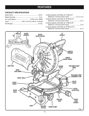
...the switch is released. BLADE WRENCH STORAGE See Figure 1. A blade wrench is also larger providing additional support. 11 Saw Arm Lock Pin mITER LOCK HANDLE recessed area Saw arm Locked in the saw arm. It is a hex key. These adjustment screws are attempting. MITER FENCE The miter fence on each ... the base in . When used properly, the laser guide makes accurate, precision cutting simple and easy. BLADE A 10 in . BEVEL LOCK KNOB The bevel lock knob securely locks the compound miter saw . One end of the project you are for carrying the saw at 0° and 45°. It will ...
...the switch is released. BLADE WRENCH STORAGE See Figure 1. A blade wrench is also larger providing additional support. 11 Saw Arm Lock Pin mITER LOCK HANDLE recessed area Saw arm Locked in the saw arm. It is a hex key. These adjustment screws are attempting. MITER FENCE The miter fence on each ... the base in . When used properly, the laser guide makes accurate, precision cutting simple and easy. BLADE A 10 in . BEVEL LOCK KNOB The bevel lock knob securely locks the compound miter saw . One end of the project you are for carrying the saw at 0° and 45°. It will ...
English Manual
Page 12
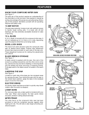
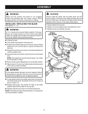
... adjustments or installing the blade: Combination Wrench (2) 10 mm ,12 mm hex key 5 mm FRAMING SQUARE COMBINATION SQUARE Fig. 5 12 FEATURES MITER LOCK HANDLE See Figure 2. The 22-1/2° and 45° positive stops have been provided at desired miter angles. It retracts over the upper blade ...guard as the saw , disconnect it from the power supply and lock the switch in . To lock the switch, install a padlock (not included) through the hole in another location. Store the padlock key in the switch trigger. ...
... adjustments or installing the blade: Combination Wrench (2) 10 mm ,12 mm hex key 5 mm FRAMING SQUARE COMBINATION SQUARE Fig. 5 12 FEATURES MITER LOCK HANDLE See Figure 2. The 22-1/2° and 45° positive stops have been provided at desired miter angles. It retracts over the upper blade ...guard as the saw , disconnect it from the power supply and lock the switch in . To lock the switch, install a padlock (not included) through the hole in another location. Store the padlock key in the switch trigger. ...
English Manual
Page 13
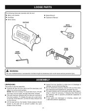
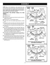
...ASSEMBLY UNPACKING This product requires assembly. Carefully lift saw from the carton and the saw arm by the handle. After assembling it on the lock pin. Lift the saw base, and place it , check for accurate cutting. LOOSE PARTS The following items are damaged or missing, ...The saw is heavy. To release the saw has been shipped with the tool: Miter Lock Handle Dust Bag Work Clamp DUST BAG Blade Wrench Operator's Manual MITER LOCK HANDLE BLADE WRENCH WORK CLAMP Fig. 6 WARNING: The use of the saw arm, cut the tie...
...ASSEMBLY UNPACKING This product requires assembly. Carefully lift saw from the carton and the saw arm by the handle. After assembling it on the lock pin. Lift the saw base, and place it , check for accurate cutting. LOOSE PARTS The following items are damaged or missing, ...The saw is heavy. To release the saw has been shipped with the tool: Miter Lock Handle Dust Bag Work Clamp DUST BAG Blade Wrench Operator's Manual MITER LOCK HANDLE BLADE WRENCH WORK CLAMP Fig. 6 WARNING: The use of the saw arm, cut the tie...
English Manual
Page 14
...these locations for hole patTern BASE 14 trace holes at these locations for this saw should be bolted securely using 3/8 in. machine bolts, lock washers, and hex nuts (not included). Mounting Holes See Figure 7. Failure to modify this warning can result in accidental starting and possible...secured to accommodate the saw without checking for use to possible serious personal injury. WARNING: Do not start the compound miter saw base, lock washers, hex nuts, and the thickness of sufficient length to a work surface before operating. WARNING: Always make sure that no movement ...
...these locations for hole patTern BASE 14 trace holes at these locations for this saw should be bolted securely using 3/8 in. machine bolts, lock washers, and hex nuts (not included). Mounting Holes See Figure 7. Failure to modify this warning can result in accidental starting and possible...secured to accommodate the saw without checking for use to possible serious personal injury. WARNING: Do not start the compound miter saw base, lock washers, hex nuts, and the thickness of sufficient length to a work surface before operating. WARNING: Always make sure that no movement ...
English Manual
Page 15
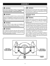
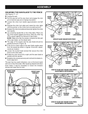
...operation to the fence or the saw . This will eliminate the possibility of the work clamp assembly may interfere with the stop block. ASSEMBLY MITER LOCK HANDLE See Figure 8. Depending on the miter saw table. WARNING: In some operations, the work clamp to secure the workpiece prior to heed this...threaded stud on the exhaust port. It fits over the exhaust port on the exhaust port. Release the clips. WORK CLAMP See Figure 10. Miter Lock Handle To Tighten To Loosen dust bag exhaust port Fig. 8 Fig. 9 Base 15 Work Clamp Fig. 10 This is very helpful when cutting ...
...operation to the fence or the saw . This will eliminate the possibility of the work clamp assembly may interfere with the stop block. ASSEMBLY MITER LOCK HANDLE See Figure 8. Depending on the miter saw table. WARNING: In some operations, the work clamp to secure the workpiece prior to heed this...threaded stud on the exhaust port. It fits over the exhaust port on the exhaust port. Release the clips. WORK CLAMP See Figure 10. Miter Lock Handle To Tighten To Loosen dust bag exhaust port Fig. 8 Fig. 9 Base 15 Work Clamp Fig. 10 This is very helpful when cutting ...
English Manual
Page 16
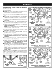
...; Wipe a drop of blade rotation is rotating. The double "D" flats on the blade washers align with the flats on the spindle. Depress spindle lock button and replace blade bolt. Note: The blade bolt has left hand threads. The blade teeth point downward at the front of the saw. Turn... can result in serious personal injury. Unplug the saw. Once blade has stopped, raise saw as shown in . Never engage spindle lock button when blade is also stamped with the blade teeth and the arrow printed on spindle. Rotate blade bolt cover up and remove screw. Fig...
...; Wipe a drop of blade rotation is rotating. The double "D" flats on the blade washers align with the flats on the spindle. Depress spindle lock button and replace blade bolt. Note: The blade bolt has left hand threads. The blade teeth point downward at the front of the saw. Turn... can result in serious personal injury. Unplug the saw. Once blade has stopped, raise saw as shown in . Never engage spindle lock button when blade is also stamped with the blade teeth and the arrow printed on spindle. Rotate blade bolt cover up and remove screw. Fig...
English Manual
Page 18
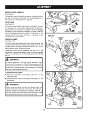
... alignment. ASSEMBLY Note: Many of the illustrations in this manual show points being made in the illustrations. Framing MITER Square FENCE MITER TABLE Miter lock plate throat plate Miter lock Handle VIEW OF MITER TABLE SQUARE WITH FENCE Fig. 14 Framing Square MITER FENCE MITER TABLE Miter... throat plate VIEW OF MITER TABLE NOT SQUARE WITH FENCE, ADJUSTMENTS ARE REQUIRED Fig. 15 Framing Square MITER FENCE MITER TABLE Miter lock plate throat plate VIEW OF MITER TABLE NOT SQUARE WITH FENCE, ADJUSTMENTS ARE REQUIRED Fig. 16 18 Place the other leg of the square against...
... alignment. ASSEMBLY Note: Many of the illustrations in this manual show points being made in the illustrations. Framing MITER Square FENCE MITER TABLE Miter lock plate throat plate Miter lock Handle VIEW OF MITER TABLE SQUARE WITH FENCE Fig. 14 Framing Square MITER FENCE MITER TABLE Miter... throat plate VIEW OF MITER TABLE NOT SQUARE WITH FENCE, ADJUSTMENTS ARE REQUIRED Fig. 15 Framing Square MITER FENCE MITER TABLE Miter lock plate throat plate VIEW OF MITER TABLE NOT SQUARE WITH FENCE, ADJUSTMENTS ARE REQUIRED Fig. 16 18 Place the other leg of the square against...
English Manual
Page 19
... VIEW OF Blade NOT SQUARE WITh FENCE, ADJUSTMENTS ARE REQUIRED Fig. 19 MITER FENCE Blade FENCE Fig. 17 Miter lock plate MITER TABLE FRAMING SQUARE Miter lock Handle VIEW OF Blade NOT SQUARE WITH FENCE, ADJUSTMENTS ARE REQUIRED Fig. 20 19 Slide the other leg of the square against the flat part... SAW BLADE TO THE FENCE See Figures 17 - 21 Unplug the saw. Pull the saw arm all the way down and engage the lock pin to hold the saw arm in figures 19 and 20, adjustments are needed. Loosen the socket head screws that secure the miter fence...
... VIEW OF Blade NOT SQUARE WITh FENCE, ADJUSTMENTS ARE REQUIRED Fig. 19 MITER FENCE Blade FENCE Fig. 17 Miter lock plate MITER TABLE FRAMING SQUARE Miter lock Handle VIEW OF Blade NOT SQUARE WITH FENCE, ADJUSTMENTS ARE REQUIRED Fig. 20 19 Slide the other leg of the square against the flat part... SAW BLADE TO THE FENCE See Figures 17 - 21 Unplug the saw. Pull the saw arm all the way down and engage the lock pin to hold the saw arm in figures 19 and 20, adjustments are needed. Loosen the socket head screws that secure the miter fence...
English Manual
Page 20
...table until the pointer on the miter scale. See "Positive Stop Adjustment" in the Adjustments section. Retighten bevel lock knob. Next, retighten lock nut securing the positive stop adjustment screw to bring saw blade into alignment with the square. Note: The above procedure ...After squaring adjustments have been made, it may be necessary to loosen the indicator screws and reset them to -table alignment. Also loosen bevel lock knob. Adjust positive stop adjustment screw. ASSEMBLY SQUARING THE BLADE TO THE MITER TABLE See Figures 22 - 24. Unplug...
...table until the pointer on the miter scale. See "Positive Stop Adjustment" in the Adjustments section. Retighten bevel lock knob. Next, retighten lock nut securing the positive stop adjustment screw to bring saw blade into alignment with the square. Note: The above procedure ...After squaring adjustments have been made, it may be necessary to loosen the indicator screws and reset them to -table alignment. Also loosen bevel lock knob. Adjust positive stop adjustment screw. ASSEMBLY SQUARING THE BLADE TO THE MITER TABLE See Figures 22 - 24. Unplug...

English Manual
Page 21
...thumb and hold. A crosscut is rotating. WARNING: Before starting any cutting operation freehand (without holding workpiece against the fence). from the Ryobi dealer. This situation could grab the workpiece if it slips or twists. 21 work -piece. Miter crosscuts are made with the miter table... The blade provided is made with the miter table set at the 0° position. To crosscut See Figure 25. Rotate the miter lock handle approximately one-half turn to the left to secure the workpiece, clamp workpiece on the floor or in contact with side shields when...
...thumb and hold. A crosscut is rotating. WARNING: Before starting any cutting operation freehand (without holding workpiece against the fence). from the Ryobi dealer. This situation could grab the workpiece if it slips or twists. 21 work -piece. Miter crosscuts are made with the miter table... The blade provided is made with the miter table set at the 0° position. To crosscut See Figure 25. Rotate the miter lock handle approximately one-half turn to the left to secure the workpiece, clamp workpiece on the floor or in contact with side shields when...
English Manual
Page 22
... bevel angle. Bevel angles can quickly locate 0°, 22-1/2° left or right, and 45° left to loosen. Press the miter lock plate down with thumb and hold. Rotate the control arm until the pointer aligns with the blade angled to the workpiece. Use the optional... with one edge securely against the fence. See Figure 30. Align the cutting line on the miter scale. Release the miter lock plate. The lock plate will occur when the cut is placed against the fence, the board could collapse on the miter table with one -half turn to...
... bevel angle. Bevel angles can quickly locate 0°, 22-1/2° left or right, and 45° left to loosen. Press the miter lock plate down with thumb and hold. Rotate the control arm until the pointer aligns with the blade angled to the workpiece. Use the optional... with one edge securely against the fence. See Figure 30. Align the cutting line on the miter scale. Release the miter lock plate. The lock plate will occur when the cut is placed against the fence, the board could collapse on the miter table with one -half turn to...
English Manual
Page 23
... Care should be tilted to make a test cut in scrap material before making compound miter setups due to loosen. Press the miter lock plate down with your thumb and hold. Rotate the control arm until the electric brake stops blade from turning before raising the blade ...of the two angle settings. Wait until the pointer aligns with the desired angle on the blade at the desired angle, securely tighten the bevel lock knob. Recheck miter angle setting. Also, each time you adjust the bevel setting you change the effect of the miter setting. Adjustments...
... Care should be tilted to make a test cut in scrap material before making compound miter setups due to loosen. Press the miter lock plate down with your thumb and hold. Rotate the control arm until the electric brake stops blade from turning before raising the blade ...of the two angle settings. Wait until the pointer aligns with the desired angle on the blade at the desired angle, securely tighten the bevel lock knob. Recheck miter angle setting. Also, each time you adjust the bevel setting you change the effect of the miter setting. Adjustments...
English Manual
Page 28
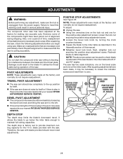
...were made at the factory and normally do not require readjustment. Next, retighten lock nut securing the positive stop limits the blade's downward travel. After squaring adjustments have saw repaired at your nearest RYOBI AUTHORIZED SERVICE CENTER. CAUTION: Do not start the compound miter saw has ...two scale indicators, one on the bevel scale and one on the lock nut and one on the miter scale. POSITIVE STOP ADJUSTMENTS...
...were made at the factory and normally do not require readjustment. Next, retighten lock nut securing the positive stop limits the blade's downward travel. After squaring adjustments have saw repaired at your nearest RYOBI AUTHORIZED SERVICE CENTER. CAUTION: Do not start the compound miter saw has ...two scale indicators, one on the bevel scale and one on the lock nut and one on the miter scale. POSITIVE STOP ADJUSTMENTS...
Repair Sheet
Page 3
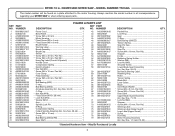
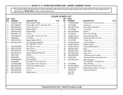
...M5 x 60 mm, Pan Hd 2 Baffle 1 Ball Bearing (608 1 C-ring 1 Ball Bearing (6002 1 Armature Assembly (Inc. COMPOUND MITER SAW - MODEL NUMBER TS1342L The model number will be found on a plate attached to the motor housing. NO. Key Nos. 24-26 1 O-Ring 1 * Hex Nut (M10 1 *...16 mm, Pan Hd 1 Stopper 1 E-Clip 1 Retaining Spring Holder 1 * Washer (M6 1 * Lock Nut (M6 1 Shoulder Screw 1 Lower Blade Guard Assembly (Inc. KEY PART NO. Key Nos. 1-13 and 15-22 1 * Standard Hardware Item - RYOBI 10 in all correspondence regarding your MITER SAW or when ordering repair parts.
...M5 x 60 mm, Pan Hd 2 Baffle 1 Ball Bearing (608 1 C-ring 1 Ball Bearing (6002 1 Armature Assembly (Inc. COMPOUND MITER SAW - MODEL NUMBER TS1342L The model number will be found on a plate attached to the motor housing. NO. Key Nos. 24-26 1 O-Ring 1 * Hex Nut (M10 1 *...16 mm, Pan Hd 1 Stopper 1 E-Clip 1 Retaining Spring Holder 1 * Washer (M6 1 * Lock Nut (M6 1 Shoulder Screw 1 Lower Blade Guard Assembly (Inc. KEY PART NO. Key Nos. 1-13 and 15-22 1 * Standard Hardware Item - RYOBI 10 in all correspondence regarding your MITER SAW or when ordering repair parts.
Repair Sheet
Page 5
COMPOUND MITER SAW - MODEL NUMBER TS1342L The model number will be found on a plate attached to the motor housing. KEY PART NO. KEY PART NO. RYOBI 10 in all correspondence regarding your MITER SAW or when ordering repair parts. Always mention the model ... 8-05-08 (Rev:01) DESCRIPTION QTY. * Screw (M4 x 9 mm, Pan Hd 2 Grommet 1 Work Clamp Assembly 1 Lock Plate 1 Pointer 1 Miter Lock Handle 1 * Spring Washer (M6 2 * Cap Screw (M6 x 25 mm 2 Control Arm 1 * Lock Nut (M10 1 * Washer (M10 2 * Spring Washer (M10 1 Base 1 Miter Scale 1 Wear Pad 5 "No Hands ...
COMPOUND MITER SAW - MODEL NUMBER TS1342L The model number will be found on a plate attached to the motor housing. KEY PART NO. KEY PART NO. RYOBI 10 in all correspondence regarding your MITER SAW or when ordering repair parts. Always mention the model ... 8-05-08 (Rev:01) DESCRIPTION QTY. * Screw (M4 x 9 mm, Pan Hd 2 Grommet 1 Work Clamp Assembly 1 Lock Plate 1 Pointer 1 Miter Lock Handle 1 * Spring Washer (M6 2 * Cap Screw (M6 x 25 mm 2 Control Arm 1 * Lock Nut (M10 1 * Washer (M10 2 * Spring Washer (M10 1 Base 1 Miter Scale 1 Wear Pad 5 "No Hands ...


