Ryobi RTS20 Support Question
Ryobi RTS20 Support Question
Find answers below for this question about Ryobi RTS20.Need a Ryobi RTS20 manual? We have 4 online manuals for this item!
Question posted by Jlughart on June 26th, 2011
Cam Washer (plastic) Piece Behind Bevel Lock Lever Broke.
Literally just unboxed this rts20 set it up. Went to move the blade to (0) Degree and Cam washer (plastic) Piece behind bevel lock lever broke?
Current Answers
Related Ryobi RTS20 Manual Pages
English Manual - Page 3

...NOT leave tools or pieces of at all instructions. Keep the work into moving parts, breakage of blade or cutter only.
NEVER LEAVE TOOL RUNNING ...TOOL.
Learn the saw while it was designed.
USE RIGHT TOOL. Serious injury could occur if the tool is tipped or if the cutting tool is in good working order.
KEEP BLADES CLEAN, SHARP, and with sufficient set...
English Manual - Page 10
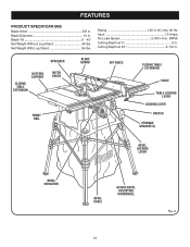
... Depth at 0 3 in . Blade Diameter 10 in . Blade Tilt 0˚ - 45˚ Net Weight Without Leg Stand 46 lbs. spreader
outfeed support
sliding table extension
MITER gauge
BLADE GUARD
FRONT RAIL
RIP FENCE
sliding table extension
SCALE
table locking lever
LOCKING LEver
SWITCH
STORAGE BRACKET(S)
BEVEL LOCKING
LEVER
BEVEL INDICATOR
BEVEL SCALE
HEIGHT/bevel ADJUSTING HANDWHEEL
10
Fig...
English Manual - Page 11

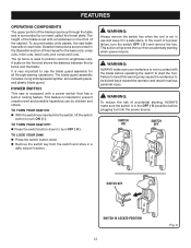
BEVEL SCALE - The blade is secured with the locking handle. WARNING:
Do not use the tool.
11 Failure to heed this operator's manual as well as a knowledge of the cabinet shows the exact blade angle.
HEIGHT/BEVEL ADJUSTING HANDWHEEL -
A sturdy metal fence guides the workpiece and is raised and lowered with the bevel locking lever. Located on the front rail...
English Manual - Page 12
...the front of the cabinet. The blade guard assembly includes: riving knife/spreader/splitter, anti-kickback pawls, and plastic blade guard.
In the event of the blade is equipped with a power switch... SWITCH
This saw is set with the blade before plugging tool into the switch, lift the switch
button to turn the switch OFF ( O ) and remove the key. TO lock your workpiece is surrounded ...
English Manual - Page 17

... dust bag
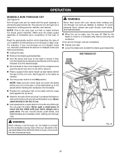
See Figure 11. Raise the saw blade and remove the throat plate. Make sure the bevel locking lever is securely pushed to the back of the larger blade wrench over the
hex nut. Make sure the blade nut is half full. Check all clearances for different blade widths.
Holding both wrenches firmly, push the...
English Manual - Page 22

... fence and cut to ensure it securely against the fence and over the saw blade area.
If positioned improperly, kickback can result in . Failure to completely stop rotating before removing the stock. push block featherboard
push stick
Bevel Locking Lever Fig. 20
3/8 in .
45°
Fig. 19
22 diameter
3-5/8 in. 3/4 in.
1/4 in.
1/8 in.
6 in...
English Manual - Page 23

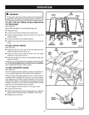
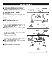
... indicator by loosening the screw and setting it by pushing the bevel lock lever all the way to the left .
The blade depth should be set so that the outer points of the blade, bringing it . Note: A 90° cut has a 0° bevel and a 45° cut has a 45° bevel.
Loosen bevel control by turning the handwheel clockwise...
English Manual - Page 24
...the rip fence by lifting the locking lever. Using a framing square, set the rip fence 2 in the Adjustment section of this manual. TO use either side of the blade. The miter gauge provides greater ...the miter gauge
See Figure 26. When making a beveled cross cut , you can be located in . There are recommended. Begin with the blade at a zero angle (straight up). Unplug...
English Manual - Page 25
..., stand behind the saw.
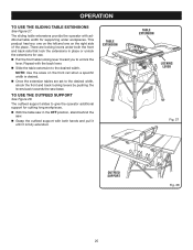
Grasp the outfeed support with both hands and pull it until it is desired.
Once the extension tables are set to the desired width. table EXTENSION
table EXTENSION
LOCKING LEVER
Fig. 27
OUTFEED SUPPORT
Fig. 28
25
The sliding table extensions provide the operator with the back...
English Manual - Page 27

... this tool.
Use the miter gauge when making a cross cut work. Always tighten the lock knob securely in place before you make a test cut on scrap wood.
Remove the rip fence by twisting the lock knob clockwise. WARNING:
Using the rip fence as shown in place by lifting the locking handle. Set the blade...
English Manual - Page 29

... before removing the workpiece.
WARNING:
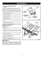
The miter gauge must be on scrap wood. Wait for the workpiece. Set the miter gauge to 90° and press the bevel locking lever towards the table to lock. Place a support (the same height as it contacts the blade to reduce the chance of injury should kickback occur.
English Manual - Page 30

... on the right side of the blade and lock down handle. Unlock the bevel locking lever. Adjust the bevel angle to full speed before removing the workpiece.
NOTE: Make sure the wood does not touch the blade before you make test cuts on the saw off. If ripping a narrow piece, use a push stick.
Adjust the scale...
English Manual - Page 32
...blade guard assembly.
Turn the bevel lock lever to the right to unlock it contacts the blade to avoid the risk of every cut is at the start and finish of personal injury. Never push a small piece of a non-through cut past the blade... to the exposed blade at the desired angle.
Set the blade to the correct depth for the workpiece and push the bevel lock lever to the left ...
English Manual - Page 34

... the bevel locking lever is securely tightened. Do not overtighten. In cutting operations, the scale will be set -ups and adjustments, a good practice is unplugged from the blade and that all clearances for making finish cuts in contact with the accessory. SMALL HEX WRENCH
Blade
arbor shaft
THROAT PLATE
34
LARGE HEX WRENCH
Fig. 43 Blade washer
Blade nut...
English Manual - Page 35
... zero properly, you may need to the ON position.
Make a test cut.
0° ADJUSTMENT BOLT
BLADE
BEVEL INDICATOR
BEVEL handle
BLADE 45°
BEVEL LOCKING
LEVER
BEVEL INDICATOR
BEVEL HANDLE
COMBINATION SQUARE
BEVEL LOCKING
LEVER Fig. 46
COMBINATION SQUARE
45° ADJUSTMENT BOLT Fig. 47
35 The angle settings of the slot. NOTE: It will be checked.
Unplug the saw...
English Manual - Page 36
... Gauge ROD
KNOB
45° ADJUSTABLE STOP SCREW
LOCK NUT
0° ADJUSTABLE STOP SCREW
Fig. 48
blade
rip fence
11
29
12
30
13
14
15
16
locking lever
screws Fig. 49
36
If the cuts are not...scale. Move the fence back and turn the framing square 180° to do so can set the miter gauge at the stop pin
with the miter gauge stop pin and adjustable stop screws using a...
English Manual - Page 39
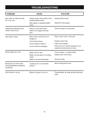
... at your nearest authorized service center. Remount blade. Locking lever is wrong type for rip cut . Change blade; Cause
Solution
Positive stops inside cabinet are clogged with correct type. Adjust positive stops.
Blade not proper for cut being made. Blade makes poor cuts. Blade does not lower when turning height/bevel adjusting handwheel. Gears or screw post inside...
Repair Sheet - Page 3
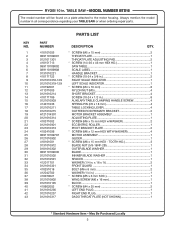
...LOCKING LEVER 4
0121010215 OUTFEED ROD PRIMARY BRACKET 2
A121014301 MOTOR BRACKET ASSEMBLY 1
0121010314 ADJUSTING PLATE 1
410371002
* SCREW (M6 x 15 mm HEX w/WASHER...TOOTH HD 3
0131010912 BLADE NUT (5/8-18NF-2B 1
0101010302 OUTER BLADE WASHER 1
089110109030 BLADE 1
0121010502 INNNER BLADE WASHER 1
0121010501 SPACER 1
412011701 WASHER (1/4 in 1
410079021
...
Repair Sheet - Page 5
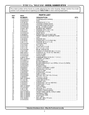
... 1 LEG KNOB LABEL 4
DUST BAG 1
HEX KEY (M5 x 75 mm 1
SWITCH KEY 1
* Standard Hardware Item -
May Be Purchased Locally COMPRESSION SPRING 1
CAM 1
SCREW (8-32 x 1 in 1
LOCKING SCREW (SS41 1
LOCKING SHIM (SUS310 1 BEVEL LOCKING LEVER 1 RUBBER PAD (NRB70 1
WASHER (D10 x D21 x 2t 1
SCREW (M4 x 7 mm 4
GEAR RACK 1
SCREW (M5 x 8 mm HEX HD 2
FRONT CABINET SUPPORT PLATE...
Repair Sheet - Page 6

... x 1.5t 4 REAR CLAMPING PLATE 1 COMPRESSION SPRING 1
RIGHT SLIDER (FRONT BLOCK 1 RIP FENCE 1 SCREW (M6 x 15 mm TRUSS HD 2
WASHER (D16 x D25 X 1.5t 2 SCREW (M4 x 10 mm TRUSS HD 1 INDICATOR 1 FRONT BLOCK 1 ROD 1 LOCKING LEVER 1 AXLE 1
RING PAD 2 SCREW (10-24 x 3/8 in all correspondence regarding your TABLE SAW or when ordering repair parts.
2
1
4
3
11...
Similar Questions

How To Replace The Bevel Lock Washer On A Ryobi Rts30
(Posted by mike1QWJani 10 years ago)


Replacement Parts
I recently purchased a Ryobi BT3000 10" Table saw w/stand. The miter gauge for it is missing; only...
I recently purchased a Ryobi BT3000 10" Table saw w/stand. The miter gauge for it is missing; only...
(Posted by mica4339 11 years ago)

How To Operate The Slide Bar.
I loosened the Slide Lock Knob.Bevel lock lever is opened. The Slide Bar seems to be stuck. No slidi...
I loosened the Slide Lock Knob.Bevel lock lever is opened. The Slide Bar seems to be stuck. No slidi...
(Posted by billgovan45 12 years ago)

Cam Melted
Ok I have a ryoby 4 stroke weed wacker modle ry34420 SN a tn 0341075 the dam cam is plastic and it m...
Ok I have a ryoby 4 stroke weed wacker modle ry34420 SN a tn 0341075 the dam cam is plastic and it m...
(Posted by smoky0 12 years ago)