
Operation Manual
Page 1
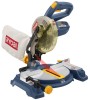
Double Insulated Your miter saw has been engineered and manufactured to our high standard for your purchase. WARNING: To reduce the risk of injury, the user must read and understand the operator's manual before using Thank you years of operation, and operator safety. this product. SAVE THIS MANUAL FOR FUTURE REFERENCE Compound Miter Saw TS1141 - OPERATOR'S MANUAL 7-1/4 in. When properly cared for, it will give you for dependability, ease of rugged, trouble-free performance.
Double Insulated Your miter saw has been engineered and manufactured to our high standard for your purchase. WARNING: To reduce the risk of injury, the user must read and understand the operator's manual before using Thank you years of operation, and operator safety. this product. SAVE THIS MANUAL FOR FUTURE REFERENCE Compound Miter Saw TS1141 - OPERATOR'S MANUAL 7-1/4 in. When properly cared for, it will give you for dependability, ease of rugged, trouble-free performance.

Operation Manual
Page 10
... with your workpiece securely against when making fine adjustments at desired bevel angles. It will cut is released. One end of servicing. FEATURES KNOW YOUR COMPOUND MITER SAW See Figure 1. Positive stop blade rotation after the switch is being made. It retracts over the upper blade guard as a knowledge of the project you...
... with your workpiece securely against when making fine adjustments at desired bevel angles. It will cut is released. One end of servicing. FEATURES KNOW YOUR COMPOUND MITER SAW See Figure 1. Positive stop blade rotation after the switch is being made. It retracts over the upper blade guard as a knowledge of the project you...
Operation Manual
Page 11
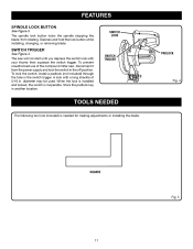
... off position. To prevent unauthorized use of 5/16 A lock with your thumb then squeeze the switch trigger. The saw will not start until you depress the switch lock with a long shackle of the compound miter saw, disconnect it from rotating. FEATURES SPINDLE LOCK BUTTON See Figure 3. Depress and hold the lock button while installing...
... off position. To prevent unauthorized use of 5/16 A lock with your thumb then squeeze the switch trigger. The saw will not start until you depress the switch lock with a long shackle of the compound miter saw, disconnect it from rotating. FEATURES SPINDLE LOCK BUTTON See Figure 3. Depress and hold the lock button while installing...

Operation Manual
Page 12
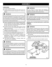
... your compound miter saw: Miter Saw Base Blade Wrench Miter Saw Head AAA Batteries (2) Dust Bag Rear Bracket/Carrying Handle Work Clamp Bevel Knob Blade Bevel Indicator and Screw Operator's Manual miter saw base ...DUST BAG WORK CLAMP AAA Batteries blade wrench miter saw head bevel knob rear bracket/ carrying handle bevel scale and screw blade Fig. 6 WARNING: The ...
... your compound miter saw: Miter Saw Base Blade Wrench Miter Saw Head AAA Batteries (2) Dust Bag Rear Bracket/Carrying Handle Work Clamp Bevel Knob Blade Bevel Indicator and Screw Operator's Manual miter saw base ...DUST BAG WORK CLAMP AAA Batteries blade wrench miter saw head bevel knob rear bracket/ carrying handle bevel scale and screw blade Fig. 6 WARNING: The ...
Operation Manual
Page 13
... packing material until you unpack it , check for interference between the blade and the miter fence. WARNING: Do not start the compound miter saw without checking for accuracy. WARNING: A rear bracket is released suddenly. screws rear bracket/ carrying handle Fig. 7 13 To release the saw arm, push down position. Hand pressure should remain on the...
... packing material until you unpack it , check for interference between the blade and the miter fence. WARNING: Do not start the compound miter saw without checking for accuracy. WARNING: A rear bracket is released suddenly. screws rear bracket/ carrying handle Fig. 7 13 To release the saw arm, push down position. Hand pressure should remain on the...

Operation Manual
Page 14
... to the stand See Figure 8. Mounting Holes See Figure 9. Carefully check the workbench after mounting to make sure the compound miter saw is shown in figure 9. Bolts should be bolted securely using a stand, the saw should be of sufficient length to a firm supporting surface such as a workbench. Each of the four mounting holes should...
... to the stand See Figure 8. Mounting Holes See Figure 9. Carefully check the workbench after mounting to make sure the compound miter saw is shown in figure 9. Bolts should be bolted securely using a stand, the saw should be of sufficient length to a firm supporting surface such as a workbench. Each of the four mounting holes should...

Operation Manual
Page 16
... See Figure 14. Remove screw from creeping toward the saw table base. Rotate the knob on this miter saw. Reinstall screw and tighten securely. Release the clips. ASSEMBLY DUST BAG See Figure 12. A dust bag is very helpful when cutting compound miters. dust bag exhaust port WORK CLAMP See Figure 13. To install... cover. The metal ring in the bag should lock in either hole on the exhaust port. The work clamp in between the grooves on the saw blade. Always make sure there is no interference with the operation of serious personal injury.
... See Figure 14. Remove screw from creeping toward the saw table base. Rotate the knob on this miter saw. Reinstall screw and tighten securely. Release the clips. ASSEMBLY DUST BAG See Figure 12. A dust bag is very helpful when cutting compound miters. dust bag exhaust port WORK CLAMP See Figure 13. To install... cover. The metal ring in the bag should lock in either hole on the exhaust port. The work clamp in between the grooves on the saw blade. Always make sure there is no interference with the operation of serious personal injury.

Operation Manual
Page 19
...be parallel as shown in figure 18. If the edge of the square against the fence. Place the other leg of the compound miter saw. ASSEMBLY Note: Many of the illustrations in this manual show points being made in good operating condition. This is intentional so that we can... the fence left or right until the pointer aligns with zero on the miter scale. Push the miter lock lever down on the miter table. Never operate the saw arm. Lift the miter lock lever. Rotate the miter table until the square and throat plate are needed. Using the...
...be parallel as shown in figure 18. If the edge of the square against the fence. Place the other leg of the compound miter saw. ASSEMBLY Note: Many of the illustrations in this manual show points being made in good operating condition. This is intentional so that we can... the fence left or right until the pointer aligns with zero on the miter scale. Push the miter lock lever down on the miter table. Never operate the saw arm. Lift the miter lock lever. Rotate the miter table until the square and throat plate are needed. Using the...
Operation Manual
Page 22
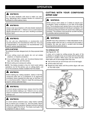
... workpiece, clamp workpiece on one side of the accessory blades available from the blade. Never perform any cutting operation, clamp or bolt the compound miter saw on the floor or in possible serious injury. Remember that a careless fraction of a second is made by the manufacturer of this warning... in a crouched position. WARNING: Always wear eye protection with side shields marked to comply with ANSI Z87.1. CUTTING WITH YOUR Compound MITER SAW WARNING: When using a work clamp Fig. 29 for picture frames moldings, door casings, and fine joinery Bevel cutting and...
... workpiece, clamp workpiece on one side of the accessory blades available from the blade. Never perform any cutting operation, clamp or bolt the compound miter saw on the floor or in possible serious injury. Remember that a careless fraction of a second is made by the manufacturer of this warning... in a crouched position. WARNING: Always wear eye protection with side shields marked to comply with ANSI Z87.1. CUTTING WITH YOUR Compound MITER SAW WARNING: When using a work clamp Fig. 29 for picture frames moldings, door casings, and fine joinery Bevel cutting and...

Operation Manual
Page 24
... until the electric brake stops blade from turning before making compound miter setups due to make this type of cut in good material. Push the miter lock lever down to lock the miter table. Loosen the bevel lock knob and move the saw , perform a dry run of the cutting operation just ... Fig. 33 Pull out the lock pin and lift saw arm must be rotated to the correct angle and the saw arm to obtain the desired cut is made using a miter angle and a bevel angle at the same time. Compound Miter Cut to secure the workpiece when possible. This type of cut ...
... until the electric brake stops blade from turning before making compound miter setups due to make this type of cut in good material. Push the miter lock lever down to lock the miter table. Loosen the bevel lock knob and move the saw , perform a dry run of the cutting operation just ... Fig. 33 Pull out the lock pin and lift saw arm must be rotated to the correct angle and the saw arm to obtain the desired cut is made using a miter angle and a bevel angle at the same time. Compound Miter Cut to secure the workpiece when possible. This type of cut ...

Operation Manual
Page 27
...other tool made. All Standard (U.S.) crown molding with extreme accuracy. Keep in the chart can be tested on the miter table using the compound features of the miter saw does an excellent job of 52° and a bottom rear angle (the section that the settings are very ...;, therefore, you will need to fit properly, crown molding must be compound mitered with 52° and 38° angles. See the chart for the application. OPERATION cutting crown molding This compound miter saw . In general, compound miter saws do not have angles of 38°. The two contact surfaces on the...
...other tool made. All Standard (U.S.) crown molding with extreme accuracy. Keep in the chart can be tested on the miter table using the compound features of the miter saw does an excellent job of 52° and a bottom rear angle (the section that the settings are very ...;, therefore, you will need to fit properly, crown molding must be compound mitered with 52° and 38° angles. See the chart for the application. OPERATION cutting crown molding This compound miter saw . In general, compound miter saws do not have angles of 38°. The two contact surfaces on the...

Operation Manual
Page 29
... at the factory for interference between the blade and the throat plate. POSITIVE STOP ADJUSTMENTS CAUTION: Do not start the compound miter saw has been adjusted at your nearest authorized service center. Note: These adjustments were made at the factory and normally do not require... readjustment. The compound miter saw without checking for making very accurate cuts. Damage could result in the Assembly section of this manual. If the ...
... at the factory for interference between the blade and the throat plate. POSITIVE STOP ADJUSTMENTS CAUTION: Do not start the compound miter saw has been adjusted at your nearest authorized service center. Note: These adjustments were made at the factory and normally do not require... readjustment. The compound miter saw without checking for making very accurate cuts. Damage could result in the Assembly section of this manual. If the ...

Operation Manual
Page 32
...ORDER REPAIR PARTS • MODEL NUMBER • SERIAL NUMBER TS1141 When ordering repair parts, always give the following information: Ryobi® is a registered trademark of Ryobi Limited used under license. Your risk from chemically-treated lumber. Please call or visit. ONE WORLD TECHNOLOGIES, INC. 1428...your nearest Authorized Service Center. The model number of Authorized Service Centers. • MODEL NO. AND SERIAL NO. Compound Miter Saw TS1141 - Please record the model number and serial number in . Double Insulated WARNING: Some dust created by power sanding...
...ORDER REPAIR PARTS • MODEL NUMBER • SERIAL NUMBER TS1141 When ordering repair parts, always give the following information: Ryobi® is a registered trademark of Ryobi Limited used under license. Your risk from chemically-treated lumber. Please call or visit. ONE WORLD TECHNOLOGIES, INC. 1428...your nearest Authorized Service Center. The model number of Authorized Service Centers. • MODEL NO. AND SERIAL NO. Compound Miter Saw TS1141 - Please record the model number and serial number in . Double Insulated WARNING: Some dust created by power sanding...

Repair Sheet
Page 1
COMPOUND MITER SAW MODEL NUMBER TS1141 REPAIR SHEET RYOBI 7-1/4 in.
COMPOUND MITER SAW MODEL NUMBER TS1141 REPAIR SHEET RYOBI 7-1/4 in.

Repair Sheet
Page 2
MODEL NUMBER TS1141 1 2 10 11 45 6 7 8 13 9 60 59 58 57 62 16 14 12 17 18 15 9 24 52 22 21 19 20 51 50 25 26 23 49 48 45 46 47 44 43 63 28 27 40 41 39 29 38 32 37 36 35 30 34 27 33 31 42 78 77 76 69 66 65 71 70 67 68 72 73 FIGURE A 79 75 74 3 61 56 55 62 56 55 53 54 63 64 2 COMPOUND MITER SAW - RYOBI 7-1/4 in.
MODEL NUMBER TS1141 1 2 10 11 45 6 7 8 13 9 60 59 58 57 62 16 14 12 17 18 15 9 24 52 22 21 19 20 51 50 25 26 23 49 48 45 46 47 44 43 63 28 27 40 41 39 29 38 32 37 36 35 30 34 27 33 31 42 78 77 76 69 66 65 71 70 67 68 72 73 FIGURE A 79 75 74 3 61 56 55 62 56 55 53 54 63 64 2 COMPOUND MITER SAW - RYOBI 7-1/4 in.

Repair Sheet
Page 3
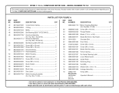
... in all correspondence regarding your 7-1/4 in . KEY PART NO. RYOBI 7-1/4 in . MODEL NUMBER TS1141 The model number will be found on a label attached to the motor housing. COMPOUND MITER SAW or when ordering parts. NUMBER DESCRIPTION PARTS LIST FOR FIGURE A ... (M4 x 12 mm 1 41 589032207 Stop Block 1 42 089240001907 Warning Label 1 43 080006014038 Spindle Lock Pin 1 44 A47000040006 E-Ring 1 3 COMPOUND MITER SAW - Key Nos. 28, 39 & 42 1 24 080006014027 Dust Bag Assembly 1 25 089240001041 Screw (M4 x 8 mm 2 26 089240001037 Laser Cover...
... in all correspondence regarding your 7-1/4 in . KEY PART NO. RYOBI 7-1/4 in . MODEL NUMBER TS1141 The model number will be found on a label attached to the motor housing. COMPOUND MITER SAW or when ordering parts. NUMBER DESCRIPTION PARTS LIST FOR FIGURE A ... (M4 x 12 mm 1 41 589032207 Stop Block 1 42 089240001907 Warning Label 1 43 080006014038 Spindle Lock Pin 1 44 A47000040006 E-Ring 1 3 COMPOUND MITER SAW - Key Nos. 28, 39 & 42 1 24 080006014027 Dust Bag Assembly 1 25 089240001041 Screw (M4 x 8 mm 2 26 089240001037 Laser Cover...
Repair Sheet
Page 4
...48 080009002086 Ball Bearing (6200 TU/TZ/CM/5C 1 49 089240001706 * Armature Assembly (Inc. Always mention the model number in all correspondence regarding your 7-1/4 in . RYOBI 7-1/4 in . MODEL NUMBER TS1141 The model number will not interchange with each other. 4 Key Nos. 51-60 1 089240001715 ** Motor Housing Assembly (Inc. Single ...1 62 080006014046 Screw (M5 x 35 mm 4 63 080009002060 Flange Washer 2 64 089240001909 Blade (7 1/4 in. Key Nos. 48 and 50 1 089240001713 ** Armature Assembly (Inc. COMPOUND MITER SAW -
...48 080009002086 Ball Bearing (6200 TU/TZ/CM/5C 1 49 089240001706 * Armature Assembly (Inc. Always mention the model number in all correspondence regarding your 7-1/4 in . RYOBI 7-1/4 in . MODEL NUMBER TS1141 The model number will not interchange with each other. 4 Key Nos. 51-60 1 089240001715 ** Motor Housing Assembly (Inc. Single ...1 62 080006014046 Screw (M5 x 35 mm 4 63 080009002060 Flange Washer 2 64 089240001909 Blade (7 1/4 in. Key Nos. 48 and 50 1 089240001713 ** Armature Assembly (Inc. COMPOUND MITER SAW -

Repair Sheet
Page 5
MODEL NUMBER TS1141 15 12 14 11 13 16 17 18 19 20 1 2 3 4 22 21 23 27 24 25 28 5 6 26 6 7 7 29 8 9 30 FIGURE B 10 36 31 32 33 34 36 35 50 53 52 51 50 49 44 43 47 5 53 52 55 59 37 54 56 38 44 43 39 40 57 42 58 41 45 46 48 47 COMPOUND MITER SAW - RYOBI 7-1/4 in.
MODEL NUMBER TS1141 15 12 14 11 13 16 17 18 19 20 1 2 3 4 22 21 23 27 24 25 28 5 6 26 6 7 7 29 8 9 30 FIGURE B 10 36 31 32 33 34 36 35 50 53 52 51 50 49 44 43 47 5 53 52 55 59 37 54 56 38 44 43 39 40 57 42 58 41 45 46 48 47 COMPOUND MITER SAW - RYOBI 7-1/4 in.

Repair Sheet
Page 6
...Logo Label (Small 1 30 089240001011 Table 1 6 MODEL NUMBER TS1141 The model number will be found on a label attached to the motor housing. COMPOUND MITER SAW - Always mention the model number in all correspondence regarding your 7-1/4 in . NUMBER DESCRIPTION QTY 1 089240001090 Bevel Handle 1 31 089240001015...17 A63000000051 O-Ring 1 47 089240001003 Screw (M5 x 18 mm 2 18 089240001024 Spindle Lock Pin 1 48 089240001018 Bolt (M8 x 23 mm, Hex Soc. COMPOUND MITER SAW or when ordering parts. RYOBI 7-1/4 in . NUMBER DESCRIPTION QTY NO.
...Logo Label (Small 1 30 089240001011 Table 1 6 MODEL NUMBER TS1141 The model number will be found on a label attached to the motor housing. COMPOUND MITER SAW - Always mention the model number in all correspondence regarding your 7-1/4 in . NUMBER DESCRIPTION QTY 1 089240001090 Bevel Handle 1 31 089240001015...17 A63000000051 O-Ring 1 47 089240001003 Screw (M5 x 18 mm 2 18 089240001024 Spindle Lock Pin 1 48 089240001018 Bolt (M8 x 23 mm, Hex Soc. COMPOUND MITER SAW or when ordering parts. RYOBI 7-1/4 in . NUMBER DESCRIPTION QTY NO.

Repair Sheet
Page 7
COMPOUND MITER SAW - RYOBI 7-1/4 in. MODEL NUMBER TS1141 YELLOW LEAD BRUSH ASSEMBLY BRUSH ASSEMBLY YELLOW LEAD MOTOR POWER CORD SLEEVE BROWN LEAD YELLOW LEAD WHITE LEAD BLACK LEAD SWITCH WIRING DIAGRAM 7
COMPOUND MITER SAW - RYOBI 7-1/4 in. MODEL NUMBER TS1141 YELLOW LEAD BRUSH ASSEMBLY BRUSH ASSEMBLY YELLOW LEAD MOTOR POWER CORD SLEEVE BROWN LEAD YELLOW LEAD WHITE LEAD BLACK LEAD SWITCH WIRING DIAGRAM 7

