
English Manual
Page 3
...'s operation. n Maintain tools with the switch is an increased risk of electric shock. n Use only accessories that is grounded. Never use brake fluids, gasoline, petroleum-based products, or any way. A wrench or a key that are doing and use an outdoor extension cord marked "W-A" or "W". The correct tool will fit in the...
...'s operation. n Maintain tools with the switch is an increased risk of electric shock. n Use only accessories that is grounded. Never use brake fluids, gasoline, petroleum-based products, or any way. A wrench or a key that are doing and use an outdoor extension cord marked "W-A" or "W". The correct tool will fit in the...
English Manual
Page 4
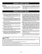
Read operator's manual carefully. n Always wear safety glasses. they are : • lead from lead-based paints, • crystalline silica from bricks and cement and other masonry products, and • arsenic and chromium from chemically-treated lumber. Constantly stay aware of ...
Read operator's manual carefully. n Always wear safety glasses. they are : • lead from lead-based paints, • crystalline silica from bricks and cement and other masonry products, and • arsenic and chromium from chemically-treated lumber. Constantly stay aware of ...

English Manual
Page 8
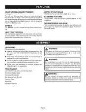
FEATURES PRODUCT SPECIFICATIONS Maximum Cutter Diameter 1-1/8 in. (29 mm) Collet 1/4 in. (6.35 mm) No Load Speed 25,000/min. Input 120 V, 60 Hz, AC only, 4.5 Amps Net Weight 3 lbs. (1.36 kg) Cord Length 10 ft. (3 m) WRENCHES ON-OFF SWITCH DEPTH OF CUT SCALE DEPTH ADJUSTMENT LATCH SUB-BASE HANDLES �� �� � � �� COLLET NUT WOODWORKING SUB-BASE Page 8 MOTOR HOUSING BASE LAMINATE SUB-BASE Fig. 1
FEATURES PRODUCT SPECIFICATIONS Maximum Cutter Diameter 1-1/8 in. (29 mm) Collet 1/4 in. (6.35 mm) No Load Speed 25,000/min. Input 120 V, 60 Hz, AC only, 4.5 Amps Net Weight 3 lbs. (1.36 kg) Cord Length 10 ft. (3 m) WRENCHES ON-OFF SWITCH DEPTH OF CUT SCALE DEPTH ADJUSTMENT LATCH SUB-BASE HANDLES �� �� � � �� COLLET NUT WOODWORKING SUB-BASE Page 8 MOTOR HOUSING BASE LAMINATE SUB-BASE Fig. 1
English Manual
Page 9
...Do not attempt to modify this tool or create accessories not recommended for use of this product, familiarize yourself with Laminate Sub-base Woodworking Sub-base Sub-base Handles (2) Ball Bearing Flush Trim Bit Carrying Case Wrenches Operator's Manual WARNING: If any parts are damaged or missing, please ... and satisfactorily operated the tool. DEPTH OF CUT SCALE The trimmer has an adjustable depth of the workpiece. WOODWORKING SUB-BASE The woodworking sub-base is misuse and could result in possible serious personal injury. n Carefully remove the tool and any parts are missing do...
...Do not attempt to modify this tool or create accessories not recommended for use of this product, familiarize yourself with Laminate Sub-base Woodworking Sub-base Sub-base Handles (2) Ball Bearing Flush Trim Bit Carrying Case Wrenches Operator's Manual WARNING: If any parts are damaged or missing, please ... and satisfactorily operated the tool. DEPTH OF CUT SCALE The trimmer has an adjustable depth of the workpiece. WOODWORKING SUB-BASE The woodworking sub-base is misuse and could result in possible serious personal injury. n Carefully remove the tool and any parts are missing do...

English Manual
Page 10
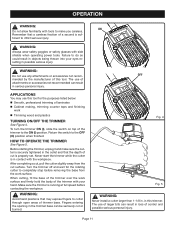
... the trimmer. WRENCH ON COLLET NUT CUTTER WRENCH ON SPINDLE FLATS Fig. 2 LAMINATE TRIMMER HANDLE(S) R3 R2 1 2 R2 WOODWORKING SUB-BASE 1 3/14/12/4 SUB-BASE SCREW(S) Fig. 3 n Turn the trimmer upright and thread the handles provided into the collet. n Place the larger end of the cutter into ... be installed once the collet nut is machined to precision tolerances to loosen the collet nut as shown in the woodworking sub-base. TO ATTACH THE WOODWORKING SUB-BASE AND HANDLES See Figure 3. This allows for the first time, it can be removed before using the same four screws....
... the trimmer. WRENCH ON COLLET NUT CUTTER WRENCH ON SPINDLE FLATS Fig. 2 LAMINATE TRIMMER HANDLE(S) R3 R2 1 2 R2 WOODWORKING SUB-BASE 1 3/14/12/4 SUB-BASE SCREW(S) Fig. 3 n Turn the trimmer upright and thread the handles provided into the collet. n Place the larger end of the cutter into ... be installed once the collet nut is machined to precision tolerances to loosen the collet nut as shown in the woodworking sub-base. TO ATTACH THE WOODWORKING SUB-BASE AND HANDLES See Figure 3. This allows for the first time, it can be removed before using the same four screws....
English Manual
Page 11
... the OFF (O) position when finished. HOW TO OPERATE THE TRIMMER See Figure 5. WARNING: Avoid hand positions that may use of trimmer base. Fingers entering the opening in contact with side shields when operating power tools. WARNING: Always wear safety goggles or safety glasses with the... Page 11 ON OFF Fig. 4 Fig. 5 WARNING: Never install a cutter larger than 1-1/8 in possible serious injury. When cutting, fit the base of the trimmer to inflict serious injury. in the collet and that a careless fraction of a second is securely tightened in this tool. OPERATION WARNING:...
... the OFF (O) position when finished. HOW TO OPERATE THE TRIMMER See Figure 5. WARNING: Avoid hand positions that may use of trimmer base. Fingers entering the opening in contact with side shields when operating power tools. WARNING: Always wear safety goggles or safety glasses with the... Page 11 ON OFF Fig. 4 Fig. 5 WARNING: Never install a cutter larger than 1-1/8 in possible serious injury. When cutting, fit the base of the trimmer to inflict serious injury. in the collet and that a careless fraction of a second is securely tightened in this tool. OPERATION WARNING:...
English Manual
Page 15
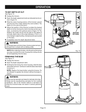
... and over. Indicator points are located on the scale indicates a 1/16 in. (1.6 mm) change in serious personal injury. NOTE: When adjusting the base, note the groove that serves as shown by the up/down arrow in figure 10. Do not attempt to obtain the desired depth of the ...trimmer without the base installed. OPERATION TO SET DEPTH OF CUT See Figure 10. row in figure 10. WARNING: Avoid open area of cut by moving the motor housing...
... and over. Indicator points are located on the scale indicates a 1/16 in. (1.6 mm) change in serious personal injury. NOTE: When adjusting the base, note the groove that serves as shown by the up/down arrow in figure 10. Do not attempt to obtain the desired depth of the ...trimmer without the base installed. OPERATION TO SET DEPTH OF CUT See Figure 10. row in figure 10. WARNING: Avoid open area of cut by moving the motor housing...

English Manual
Page 16
OPERATION USING THE WOODWORKING SUB-BASE WITH HANDLES The woodworking sub-base with two hands, similar to grasping and holding a router. ROUTING GROOVES IN A CIRCLE See Figure 12. n There are 4 in. (101.6 mm), 5 in. (127 mm) or 6 ...in. (152.4 mm) in . (152.4 mm) circular grooves. n Select the radius for that are three holes marked R2", R2-1/2", and R3" on the sub-base. See the arrow in a clockwise direction only. The handles allow you to the edge of the workpiece. Each number represents a radius and may be used...
OPERATION USING THE WOODWORKING SUB-BASE WITH HANDLES The woodworking sub-base with two hands, similar to grasping and holding a router. ROUTING GROOVES IN A CIRCLE See Figure 12. n There are 4 in. (101.6 mm), 5 in. (127 mm) or 6 ...in. (152.4 mm) in . (152.4 mm) circular grooves. n Select the radius for that are three holes marked R2", R2-1/2", and R3" on the sub-base. See the arrow in a clockwise direction only. The handles allow you to the edge of the workpiece. Each number represents a radius and may be used...

English Manual
Page 17
... shown by the arrow in . (6.4 mm) thick or less to the guiding portion of the horizontal and vertical lines at increasing depths with the trimmer base. n The thrust is required, make the cut is from the edge of the cutter. If a deep cut from right to be at least as ... the center of desired groove on the workpiece with the centerline on the workpiece and make successive passes at the center of the woodworking sub-base indicates the center of the workpiece. OPERATION ROUTING GROOVES PARALLEL TO AN EDGE See Figure 13. NOTE: The board being cut a straight parallel line up...
... shown by the arrow in . (6.4 mm) thick or less to the guiding portion of the horizontal and vertical lines at increasing depths with the trimmer base. n The thrust is required, make the cut is from the edge of the cutter. If a deep cut from right to be at least as ... the center of desired groove on the workpiece with the centerline on the workpiece and make successive passes at the center of the woodworking sub-base indicates the center of the workpiece. OPERATION ROUTING GROOVES PARALLEL TO AN EDGE See Figure 13. NOTE: The board being cut a straight parallel line up...
English Manual
Page 18
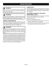
... and grindings are susceptible to clean the tool using compressed air. Electric tools used on these materials, it is securely tightened by checking the sub-base. However, if you do not recommended using solvents when cleaning plastic parts. Use clean cloths to bearings, brushes, commutators, etc. n Using a small adjusting wrench, tighten... glasses with plastic parts. Use of the unit under normal operating conditions. Page 18 ADJUSTING TENSION ON THE DEPTH ADJUSTMENT LATCH With use only identical Ryobi replacement parts. If operation is required.
... and grindings are susceptible to clean the tool using compressed air. Electric tools used on these materials, it is securely tightened by checking the sub-base. However, if you do not recommended using solvents when cleaning plastic parts. Use clean cloths to bearings, brushes, commutators, etc. n Using a small adjusting wrench, tighten... glasses with plastic parts. Use of the unit under normal operating conditions. Page 18 ADJUSTING TENSION ON THE DEPTH ADJUSTMENT LATCH With use only identical Ryobi replacement parts. If operation is required.
Repair Sheet
Page 3
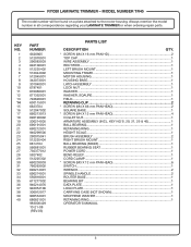
...WIRE ASSEMBLY 1 4 840108001 RECTIFIER...1 5 512225402 LEFT BRUSH MOUNT 1 6 512044002 MOUNTING FRAME 1 7 512045001 MOTOR HOUSING 1 8 342073001 HOUSING BASE 1 9 301040001 LATCH ASSEMBLY 1 10 6797401 LOCK NUT...1 11 670060001 WASHER...1 12 671352001 WASHER, SQAURE 1 13 740628001 FIELD...1 14 630115001 ... 1 40 680821001 RETAINING RING 1 983000429 OPERATOR'S MANUAL 10-21-08 (REV:03) 3 KEY NO. RYOBI LAMINATE TRIMMER - MODEL NUMBER TR45 The model number will be found on a plate attached to the ...
...WIRE ASSEMBLY 1 4 840108001 RECTIFIER...1 5 512225402 LEFT BRUSH MOUNT 1 6 512044002 MOUNTING FRAME 1 7 512045001 MOTOR HOUSING 1 8 342073001 HOUSING BASE 1 9 301040001 LATCH ASSEMBLY 1 10 6797401 LOCK NUT...1 11 670060001 WASHER...1 12 671352001 WASHER, SQAURE 1 13 740628001 FIELD...1 14 630115001 ... 1 40 680821001 RETAINING RING 1 983000429 OPERATOR'S MANUAL 10-21-08 (REV:03) 3 KEY NO. RYOBI LAMINATE TRIMMER - MODEL NUMBER TR45 The model number will be found on a plate attached to the ...


