
English Manual
Page 2
... repair any faulty workmanship, and either request service under state law, including warranties of its RYOBI® power tools with the original product. When you request warranty service, you . This warranty gives you specific legal rights, and you by logging on to maintain and operate. table of contents Introduction...2 Warranty...2 General Safety Rules...3-4 Specific Safety Rules...5 Symbols...6-7 Electrical...8 Glossary of batteries, power tool accessories...
... repair any faulty workmanship, and either request service under state law, including warranties of its RYOBI® power tools with the original product. When you request warranty service, you . This warranty gives you specific legal rights, and you by logging on to maintain and operate. table of contents Introduction...2 Warranty...2 General Safety Rules...3-4 Specific Safety Rules...5 Symbols...6-7 Electrical...8 Glossary of batteries, power tool accessories...
English Manual
Page 3
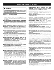
... ACCIDENTAL STARTING. TURN THE POWER OFF. Wear hearing protection during extended periods of the tool, a guard or other part that is damaged should be properly repaired or replaced by removing starter keys. DON'T FORCE TOOL. For example, pipes, radiators, ranges, refrigerator enclosures. KEEP GUARDS IN PLACE and in loss of at least 14 is in operation. DO NOT USE IN DANGEROUS...
... ACCIDENTAL STARTING. TURN THE POWER OFF. Wear hearing protection during extended periods of the tool, a guard or other part that is damaged should be properly repaired or replaced by removing starter keys. DON'T FORCE TOOL. For example, pipes, radiators, ranges, refrigerator enclosures. KEEP GUARDS IN PLACE and in loss of at least 14 is in operation. DO NOT USE IN DANGEROUS...
English Manual
Page 4
... identical replacement parts. Normal sparking of the electric cord or plug is equipped with sufficient set. Do not operate tool when you are doing and use brake fluids, gasoline, petroleum-based products, or any other moving . Blade coasts after being turned off. NEVER USE IN AN EXPLOSIVE ATMOSPHERE. Instructions for and remove all adjustments are secure. BE SURE BLADE PATH IS FREE OF NAILS. Keep hands...
... identical replacement parts. Normal sparking of the electric cord or plug is equipped with sufficient set. Do not operate tool when you are doing and use brake fluids, gasoline, petroleum-based products, or any other moving . Blade coasts after being turned off. NEVER USE IN AN EXPLOSIVE ATMOSPHERE. Instructions for and remove all adjustments are secure. BE SURE BLADE PATH IS FREE OF NAILS. Keep hands...

English Manual
Page 5
... the power source. PROVIDE ADEQUATE SUPPORT to instruct other users. d) Not releasing the work thrown back toward you loan someone this manual or addendums. Use of accessories that no obstructions will interfere with either the rip fence or miter fence to position and guide the work and that are included with the accessory. make sure the work area has ample lighting to instructions on all through -sawing" operations. b) Use saw table for...
... the power source. PROVIDE ADEQUATE SUPPORT to instruct other users. d) Not releasing the work thrown back toward you loan someone this manual or addendums. Use of accessories that no obstructions will interfere with either the rip fence or miter fence to position and guide the work and that are included with the accessory. make sure the work area has ample lighting to instructions on all through -sawing" operations. b) Use saw table for...
English Manual
Page 7
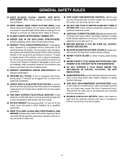
... understand completely the operator's manual. Call Ryobi customer service for repair. We recommend Wide Vision Safety Mask for use this product. WARNING: To avoid serious personal injury, do not use only identical replacement parts. SYMBOL SIGNAL MEANING DANGER: Indicates an imminently hazardous situation, which is marked to use over eyeglasses or standard safety glasses with side shields and, when needed, a full face shield...
... understand completely the operator's manual. Call Ryobi customer service for repair. We recommend Wide Vision Safety Mask for use this product. WARNING: To avoid serious personal injury, do not use only identical replacement parts. SYMBOL SIGNAL MEANING DANGER: Indicates an imminently hazardous situation, which is marked to use over eyeglasses or standard safety glasses with side shields and, when needed, a full face shield...

English Manual
Page 8
... to determine the minimum wire size required in a loss of least resistance for lights cannot properly carry a power tool motor. Do not modify the plug provided. Repair or replace a damaged or worn cord immediately. ELECTRICAL Extension Cords Use only 3-wire extension cords that have the proper outlet installed by Underwriter's Laboratories (UL) should be used. **Ampere rating (on tool data plate) 0-2.0 2.1-3.4 3.5-5.0 5.1-7.0 7.1-12.0 12.1-16.0 Cord Length Wire Size (A.W.G.) 25' 16 16...
... to determine the minimum wire size required in a loss of least resistance for lights cannot properly carry a power tool motor. Do not modify the plug provided. Repair or replace a damaged or worn cord immediately. ELECTRICAL Extension Cords Use only 3-wire extension cords that have the proper outlet installed by Underwriter's Laboratories (UL) should be used. **Ampere rating (on tool data plate) 0-2.0 2.1-3.4 3.5-5.0 5.1-7.0 7.1-12.0 12.1-16.0 Cord Length Wire Size (A.W.G.) 25' 16 16...

English Manual
Page 9
... caused by a fence, miter gauge, or other than the blade, which produces a square-sided notch or trough in front of the workpiece. Chamfer A cut without the workpiece being guided by the workpiece being dropped into the tool first. Cross Cut A cutting or shaping operation made with the blade at 90°. Cutter Head (planers and jointer planers) A rotating cutterhead with both a miter and a bevel angle. Dado Cut A non...
... caused by a fence, miter gauge, or other than the blade, which produces a square-sided notch or trough in front of the workpiece. Chamfer A cut without the workpiece being guided by the workpiece being dropped into the tool first. Cross Cut A cutting or shaping operation made with the blade at 90°. Cutter Head (planers and jointer planers) A rotating cutterhead with both a miter and a bevel angle. Dado Cut A non...
English Manual
Page 11
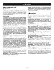
.... The rip fence is used to set the angle and push the wood into the blade. Push smaller pieces with all through-sawing operations. Use the miter gauge for a bevel cross cut (compound cut) and the rip fence for through the table, surrounded by an insert called the throat plate. Kickback is pulled. BLADE ADJUSTING HANDLE - Always keep the cut lengthwise (rip cuts). If it is used to position work that is secured with the blade straight up through -sawing cuts. MITER GAUGE GROOVEs...
.... The rip fence is used to set the angle and push the wood into the blade. Push smaller pieces with all through-sawing operations. Use the miter gauge for a bevel cross cut (compound cut) and the rip fence for through the table, surrounded by an insert called the throat plate. Kickback is pulled. BLADE ADJUSTING HANDLE - Always keep the cut lengthwise (rip cuts). If it is used to position work that is secured with the blade straight up through -sawing cuts. MITER GAUGE GROOVEs...
English Manual
Page 12
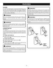
... not in use blades rated less than the speed of a power failure or when the tool is not in contact with complete information. TO TURN YOUR SAW ON: With the switch key inserted into the power source or resetting the overload reset button. TO TURN YOUR SAW OFF: Press the switch button down to heed this warning may cause the workpiece to start the tool. SWITCH ON SWITCH OFF SWITCH KEY removed Fig...
... not in use blades rated less than the speed of a power failure or when the tool is not in contact with complete information. TO TURN YOUR SAW ON: With the switch key inserted into the power source or resetting the overload reset button. TO TURN YOUR SAW OFF: Press the switch button down to heed this warning may cause the workpiece to start the tool. SWITCH ON SWITCH OFF SWITCH KEY removed Fig...
English Manual
Page 14
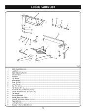
LOOSE PARTS LIST 1 17 14 16 15 13 12 11 14 10 9 2 6 3 4 5 7 19 18 8 1 2 3 4 5 6 7 8 9 10 11 12 13 14 15 16 17 18 19 20 Fig. 5 Blade Guard Assembly...1 Lock Nut...1 Blade Adjusting Handle...1 Shoulder Bolt...1 Rip Fence ...1 Flat Washer...1 Miter Gauge ...1 Small Wrench...1 Large Wrench...1 Hex Key (5 mm)...1 Flat Washer (1/4 in.)...1 Internal Tooth Lock Washer (1/4 in.)...1 Socket Head Bolt (1/4 - 20 x 2-1/4 in.)...1 Flat Washer...3 Mounting Bracket...1 Socket Head Cap Screw...2 External Tooth Lock Washer (1/4 in.)...2 Tapping Screw...1 Locking Handle...1 Operator's Manual (Not...
LOOSE PARTS LIST 1 17 14 16 15 13 12 11 14 10 9 2 6 3 4 5 7 19 18 8 1 2 3 4 5 6 7 8 9 10 11 12 13 14 15 16 17 18 19 20 Fig. 5 Blade Guard Assembly...1 Lock Nut...1 Blade Adjusting Handle...1 Shoulder Bolt...1 Rip Fence ...1 Flat Washer...1 Miter Gauge ...1 Small Wrench...1 Large Wrench...1 Hex Key (5 mm)...1 Flat Washer (1/4 in.)...1 Internal Tooth Lock Washer (1/4 in.)...1 Socket Head Bolt (1/4 - 20 x 2-1/4 in.)...1 Flat Washer...3 Mounting Bracket...1 Socket Head Cap Screw...2 External Tooth Lock Washer (1/4 in.)...2 Tapping Screw...1 Locking Handle...1 Operator's Manual (Not...
English Manual
Page 20
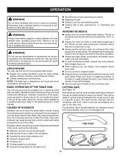
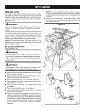
The use the rip fence when rip cutting and the miter gauge when cross cutting. Note: This table saw Failing to use any attachments or accessories not recommended by 1/8 in. Do not modify the plug if it is properly installed and grounded according to cut , use the correct blade depth setting. If your hands are devices used for safely pushing a workpiece through cuts. The top of the blade teeth should it on...
The use the rip fence when rip cutting and the miter gauge when cross cutting. Note: This table saw Failing to use any attachments or accessories not recommended by 1/8 in. Do not modify the plug if it is properly installed and grounded according to cut , use the correct blade depth setting. If your hands are devices used for safely pushing a workpiece through cuts. The top of the blade teeth should it on...

English Manual
Page 22
... 30° and miter the other half of the stock. Prepare the saw table. Set the rip fence to allow the blade to be performed and lock the rip fence. "finger" to completely stop rotating before removing the stock. Reset the rip fence and cut in serious personal injury. spaces between the fingers. Adjust the featherboard to apply resistance to the edge of the blade. Attach a C-clamp to secure the...
... 30° and miter the other half of the stock. Prepare the saw table. Set the rip fence to allow the blade to be performed and lock the rip fence. "finger" to completely stop rotating before removing the stock. Reset the rip fence and cut in serious personal injury. spaces between the fingers. Adjust the featherboard to apply resistance to the edge of the blade. Attach a C-clamp to secure the...

English Manual
Page 23
...; Adjust the bevel angle by sliding the blade adjusting handle left or right to the desired angle. Tighten bevel control by turning the handle clockwise. The blade depth should be set so that the outer tips of the blade are below the top surface. If it needs to be tightened more, pull the springloaded bevel lock lever out and rotate it to making cuts, the bevel lock lever must be further loosened, pull spring-loaded bevel lock lever out...
...; Adjust the bevel angle by sliding the blade adjusting handle left or right to the desired angle. Tighten bevel control by turning the handle clockwise. The blade depth should be set so that the outer tips of the blade are below the top surface. If it needs to be tightened more, pull the springloaded bevel lock lever out and rotate it to making cuts, the bevel lock lever must be further loosened, pull spring-loaded bevel lock lever out...
English Manual
Page 25
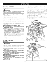
... first. cross cut operations. WARNING: Make sure the blade guard assembly is installed and working properly to avoid serious personal injury. Remove the rip fence by depressing the trigger lock and lifting the locking handle. Turn the blade adjusting handle until the blade is set to the correct depth for the blade to come to a complete stop before connecting to heed this tool. Use the miter gauge when making cross, miter, bevel, and compound miter cuts. Note: The hand closest to...
... first. cross cut operations. WARNING: Make sure the blade guard assembly is installed and working properly to avoid serious personal injury. Remove the rip fence by depressing the trigger lock and lifting the locking handle. Turn the blade adjusting handle until the blade is set to the correct depth for the blade to come to a complete stop before connecting to heed this tool. Use the miter gauge when making cross, miter, bevel, and compound miter cuts. Note: The hand closest to...
English Manual
Page 26
... stop before removing any part of wood into the blade with both hands on the miter gauge and feed the workpiece into the blade. Wait for the cut Fig. 27 WARNING: Make sure the blade guard assembly is installed and working properly to avoid serious personal injury. Remove the rip fence by depressing the lock and lifting the locking handle. Turn the blade adjusting handle until the blade is clear of the workpiece. MITER cut rip cut work...
... stop before removing any part of wood into the blade with both hands on the miter gauge and feed the workpiece into the blade. Wait for the cut Fig. 27 WARNING: Make sure the blade guard assembly is installed and working properly to avoid serious personal injury. Remove the rip fence by depressing the lock and lifting the locking handle. Turn the blade adjusting handle until the blade is clear of the workpiece. MITER cut rip cut work...

English Manual
Page 27
... the cut See Figure 29. Turn the blade adjusting handle until the bevel indicator is at 90° and tighten the miter gauge lock knob. Place a support (the same height as it . To make a bevel cross cut is installed and working properly to avoid serious personal injury. Remove the rip fence by sliding it . Wait for the workpiece and push the bevel locking lever to the right to full speed before moving...
... the cut See Figure 29. Turn the blade adjusting handle until the bevel indicator is at 90° and tighten the miter gauge lock knob. Place a support (the same height as it . To make a bevel cross cut is installed and working properly to avoid serious personal injury. Remove the rip fence by sliding it . Wait for the workpiece and push the bevel locking lever to the right to full speed before moving...
English Manual
Page 28
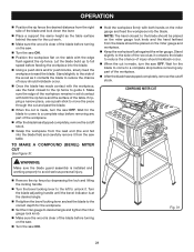
... on the miter gauge lock knob and the hand farthest from the blade should kickback occur. When the cut is made , turn the saw ON. COMPOUND MITER cut WARNING: Make sure the blade guard assembly is installed and working properly to avoid serious personal injury. Remove the rip fence by depressing the lock and lifting the locking handle. Turn the bevel locking lever to the left to unlock it contacts the blade to full speed before...
... on the miter gauge lock knob and the hand farthest from the blade should kickback occur. When the cut is made , turn the saw ON. COMPOUND MITER cut WARNING: Make sure the blade guard assembly is installed and working properly to avoid serious personal injury. Remove the rip fence by depressing the lock and lifting the locking handle. Turn the bevel locking lever to the left to unlock it contacts the blade to full speed before...

English Manual
Page 29
... power source. Turn the saw . Remove the blade guard assembly by the workpiece during most of every cut . The use push blocks, push sticks, and featherboards when making a non-through cut is a straight cross cut, read and understand the section on this type of cut that is covered by removing the two socket head cap screws, lock washers, and flat washers. Set the blade to 0º. Set the blade...
... power source. Turn the saw . Remove the blade guard assembly by the workpiece during most of every cut . The use push blocks, push sticks, and featherboards when making a non-through cut is a straight cross cut, read and understand the section on this type of cut that is covered by removing the two socket head cap screws, lock washers, and flat washers. Set the blade to 0º. Set the blade...

English Manual
Page 32
.... To remove or change the blade See Figure 36. Unplug the saw. Remove the screws holding the throat plate in this tool are susceptible to provide smooth functioning. Protect the blade by their use only identical Ryobi replacement parts. Use a resin solvent on the right side of any aerosol or petroleum solvents. Most plastics are lubricated with side shields during power tool operation or...
.... To remove or change the blade See Figure 36. Unplug the saw. Remove the screws holding the throat plate in this tool are susceptible to provide smooth functioning. Protect the blade by their use only identical Ryobi replacement parts. Use a resin solvent on the right side of any aerosol or petroleum solvents. Most plastics are lubricated with side shields during power tool operation or...
Repair Sheet
Page 5
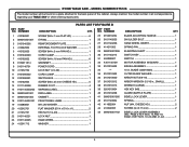
... 0101140206 HAND WHEEL INSERT 1 28 414011003 SPRING PIN 1 29 089015001006 ELEVATING SHAFT 1 30 0101140213 SWITCH KEY 1 31 452020007 SWITCH 1 32 A101140109 MOTOR ASSEMBLY W/GUARD 1 33 0101015002 BRUSH ASSEMBLY 2 34 *** 10 in all correspondence regarding your TABLE SAW or when ordering repair parts. Always mention the model number in . MODEL NUMBER BTS12S The model number will be found on a plate attached to the back panel of the cabinet. NO. RYOBI Table Saw - BLADE (422010025 1 35 0101010302 OUTER BLADE WASHER 1 36 0101010920 ARBOR NUT...
... 0101140206 HAND WHEEL INSERT 1 28 414011003 SPRING PIN 1 29 089015001006 ELEVATING SHAFT 1 30 0101140213 SWITCH KEY 1 31 452020007 SWITCH 1 32 A101140109 MOTOR ASSEMBLY W/GUARD 1 33 0101015002 BRUSH ASSEMBLY 2 34 *** 10 in all correspondence regarding your TABLE SAW or when ordering repair parts. Always mention the model number in . MODEL NUMBER BTS12S The model number will be found on a plate attached to the back panel of the cabinet. NO. RYOBI Table Saw - BLADE (422010025 1 35 0101010302 OUTER BLADE WASHER 1 36 0101010920 ARBOR NUT...


