

English Manual
Page 1
WARNING: To reduce the risk of operation, and operator safety. DOUBLE INSULATED Your new router has been engineered and manufactured to Ryobi's high standard for buying Ryobi tools. Thank you years of rugged, trouble-free performance. Properly cared for, it will give you again for dependability, ease of injury, the user must read and understand the operator's manual. SAVE THIS MANUAL FOR FUTURE REFERENCE OPERATOR'S MANUAL ELECTRONIC PLUNGE ROUTER RE180PL VARIABLE SPEED -
WARNING: To reduce the risk of operation, and operator safety. DOUBLE INSULATED Your new router has been engineered and manufactured to Ryobi's high standard for buying Ryobi tools. Thank you years of rugged, trouble-free performance. Properly cared for, it will give you again for dependability, ease of injury, the user must read and understand the operator's manual. SAVE THIS MANUAL FOR FUTURE REFERENCE OPERATOR'S MANUAL ELECTRONIC PLUNGE ROUTER RE180PL VARIABLE SPEED -

English Manual
Page 2
... ...6 ■ Features ...7-9 ■ Adjustments ...10-14 ■ Operation ...15-20 ■ Maintenance ...20-22 ■ Accessories ...23 ■ Parts, Ordering, and Service ...24 INTRODUCTION Your router has many features for making the use of this tool making it is intended, you will enjoy years of safe, reliable service.
... ...6 ■ Features ...7-9 ■ Adjustments ...10-14 ■ Operation ...15-20 ■ Maintenance ...20-22 ■ Accessories ...23 ■ Parts, Ordering, and Service ...24 INTRODUCTION Your router has many features for making the use of this tool making it is intended, you will enjoy years of safe, reliable service.
English Manual
Page 6
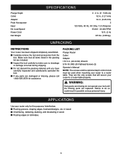
....8 mm) Wrench 5/16-18 UNC-2A Flathead Screws (2) Operator's Manual NOTE: The screws and the optional depth control knob must be used when mounting your router to a router table properly. in wood. ■ Chamfering, rabbeting, dadoing, and dovetailing in . (6.35 mm) 2 120 Volts, 60 Hz, AC Only, 10.0 Amperes ...15,000 - 23,000 RPM 10 ft. (3 m) 8.5 lbs. (3.86 kg.) UNPACKING INSTRUCTIONS Your router has been shipped completely assembled. ■ Carefully remove the tool and accessories from the box. They are replaced. PACKING LIST Plunge...
....8 mm) Wrench 5/16-18 UNC-2A Flathead Screws (2) Operator's Manual NOTE: The screws and the optional depth control knob must be used when mounting your router to a router table properly. in wood. ■ Chamfering, rabbeting, dadoing, and dovetailing in . (6.35 mm) 2 120 Volts, 60 Hz, AC Only, 10.0 Amperes ...15,000 - 23,000 RPM 10 ft. (3 m) 8.5 lbs. (3.86 kg.) UNPACKING INSTRUCTIONS Your router has been shipped completely assembled. ■ Carefully remove the tool and accessories from the box. They are replaced. PACKING LIST Plunge...
English Manual
Page 7
... and at different angles. As the name implies your nearest authorized service center for heavy duty performance. HEAVY DUTY MOTOR Your router has a powerful 10 amp motor with double insulation requires extreme care and knowledge of power and overheating. The motor also has... an outlet, double-check the power supply. The electronic feature of the guess work that will be grounded. VARIABLE SPEED Your router has advanced electronic features, designed to loosen collet nut and change cutters. DOUBLE INSULATION Double insulation is a versatile woodworking tool that...
... and at different angles. As the name implies your nearest authorized service center for heavy duty performance. HEAVY DUTY MOTOR Your router has a powerful 10 amp motor with double insulation requires extreme care and knowledge of power and overheating. The motor also has... an outlet, double-check the power supply. The electronic feature of the guess work that will be grounded. VARIABLE SPEED Your router has advanced electronic features, designed to loosen collet nut and change cutters. DOUBLE INSULATION Double insulation is a versatile woodworking tool that...

English Manual
Page 8
FEATURES FRONT VIEW OF ROUTER SCALE ZERO RESET INDICATOR OPERATION SPEED SELECTION SIGHT WINDOW VARIABLE SPEED CONTROL SELECTOR HANDLE LOCK KNOB STOP BAR ACCU-STOPTM MICRO-ADJUSTABLE DEPTH STOP EACH 90O ROTATION OF DEPTH STOP KNOB EQUALS 1/64 in. (0.4 mm) CHANGE IN DEPTH OF CUT 8 SPINDLE LOCK CHIP SHIELD EACH COMPLETE ROTATION (360O) OF DEPTH STOP KNOB EQUALS 1/16 in. (1.6 mm) CHANGE IN DEPTH OF CUT Fig. 1
FEATURES FRONT VIEW OF ROUTER SCALE ZERO RESET INDICATOR OPERATION SPEED SELECTION SIGHT WINDOW VARIABLE SPEED CONTROL SELECTOR HANDLE LOCK KNOB STOP BAR ACCU-STOPTM MICRO-ADJUSTABLE DEPTH STOP EACH 90O ROTATION OF DEPTH STOP KNOB EQUALS 1/64 in. (0.4 mm) CHANGE IN DEPTH OF CUT 8 SPINDLE LOCK CHIP SHIELD EACH COMPLETE ROTATION (360O) OF DEPTH STOP KNOB EQUALS 1/16 in. (1.6 mm) CHANGE IN DEPTH OF CUT Fig. 1

English Manual
Page 9
POWER CORD FEATURES REAR VIEW OF ROUTER PLUNGE LOCK LEVER HEX NUT(S) COLLET NUT ROUTER BASE SUBBASE 15 16 15/16 in. (23.8 mm) WRENCH 1/4 in a hazardous condition leading to modify this tool or create accessories not recommended for use with this tool. Any such alteration or modification is misuse and could result in . (6.35 mm) ADAPTOR Fig. 2 WARNING: Do not attempt to possible serious personal injury. 9
POWER CORD FEATURES REAR VIEW OF ROUTER PLUNGE LOCK LEVER HEX NUT(S) COLLET NUT ROUTER BASE SUBBASE 15 16 15/16 in. (23.8 mm) WRENCH 1/4 in a hazardous condition leading to modify this tool or create accessories not recommended for use with this tool. Any such alteration or modification is misuse and could result in . (6.35 mm) ADAPTOR Fig. 2 WARNING: Do not attempt to possible serious personal injury. 9

English Manual
Page 10
...35 mm) diameter shanks, insert the 1/4 in. (6.35 mm) adaptor into the 1/2 in. (12.7 mm) collet. ■ Insert shank of router base onto collet nut and turn counterclockwise to loosen. NOTE: The collet is loose. WARNING: If you are changing a cutter immediately after loosening collet ...nut. CUTTER INSTALLATION See Figures 3 and 4. ■ UNPLUG YOUR ROUTER. See Figure 3. ■ Place the wrench provided through front of cutter until shank bottoms out, then pull it out 1/16 in. (1.6 mm)...
...35 mm) diameter shanks, insert the 1/4 in. (6.35 mm) adaptor into the 1/2 in. (12.7 mm) collet. ■ Insert shank of router base onto collet nut and turn counterclockwise to loosen. NOTE: The collet is loose. WARNING: If you are changing a cutter immediately after loosening collet ...nut. CUTTER INSTALLATION See Figures 3 and 4. ■ UNPLUG YOUR ROUTER. See Figure 3. ■ Place the wrench provided through front of cutter until shank bottoms out, then pull it out 1/16 in. (1.6 mm)...

English Manual
Page 11
...-flute bits, are designed to remove larger amounts of wood in two or more passes. TO ADJUST DEPTH OF CUT ■ UNPLUG YOUR ROUTER. CUTTER EXTENDED BELOW SUBBASE Fig. 7 11 We recommend that cuts be made to remove only small amounts of wood. See Figure 6. ADJUSTMENTS... that extra force is best to make the cut in router base. A lightweight, low horsepower router is inside router subbase. ■ Place router on router motor. Large bits, such as white pine, than the opening in several factors: horsepower of router motor, type of cutter being used, and type of wood...
...-flute bits, are designed to remove larger amounts of wood in two or more passes. TO ADJUST DEPTH OF CUT ■ UNPLUG YOUR ROUTER. CUTTER EXTENDED BELOW SUBBASE Fig. 7 11 We recommend that cuts be made to remove only small amounts of wood. See Figure 6. ADJUSTMENTS... that extra force is best to make the cut in router base. A lightweight, low horsepower router is inside router subbase. ■ Place router on router motor. Large bits, such as white pine, than the opening in several factors: horsepower of router motor, type of cutter being used, and type of wood...

English Manual
Page 12
... the spring will move 1/8 in. (3.2 mm) from depth adjustment rod. TO INSTALL OPTIONAL DEPTH CONTROL KNOB See Figure 8. ■ UNPLUG YOUR ROUTER. For example, if setting 1/8 in. (3.2 mm) depth of cut, the zero-reset indicator will cause depth control knob to pop off depth adjustment...control knob without compression spring could result in . (25.4 mm) reference point. ■ Tighten lock knob securely. ■ Position your plunge router. For example, align red line with a 15/16 in possible serious injury. OPTIONAL DEPTH CONTROL KNOB An optional depth control knob is mounted ...
... the spring will move 1/8 in. (3.2 mm) from depth adjustment rod. TO INSTALL OPTIONAL DEPTH CONTROL KNOB See Figure 8. ■ UNPLUG YOUR ROUTER. For example, if setting 1/8 in. (3.2 mm) depth of cut, the zero-reset indicator will cause depth control knob to pop off depth adjustment...control knob without compression spring could result in . (25.4 mm) reference point. ■ Tighten lock knob securely. ■ Position your plunge router. For example, align red line with a 15/16 in possible serious injury. OPTIONAL DEPTH CONTROL KNOB An optional depth control knob is mounted ...

English Manual
Page 13
...be performed. WARNING: Failure to make depth of cut setting 1/64 in . (12.7 mm) from 0 to its uppermost position. ■ Plunge router until cutter reaches the approximate desired depth of cut. ■ Lock plunge lock lever, temporarily locking cutter at each 90° rotation of cut ...OPTIONAL DEPTH CONTROL KNOB ■ Loosen lock knob and raise stop flange. Always lock cutter in successive passes by plunging router until it possible to unplug your router could result in accidental starting point for depth of cut changes to be made from the initial setting of the stop ...
...be performed. WARNING: Failure to make depth of cut setting 1/64 in . (12.7 mm) from 0 to its uppermost position. ■ Plunge router until cutter reaches the approximate desired depth of cut. ■ Lock plunge lock lever, temporarily locking cutter at each 90° rotation of cut ...OPTIONAL DEPTH CONTROL KNOB ■ Loosen lock knob and raise stop flange. Always lock cutter in successive passes by plunging router until it possible to unplug your router could result in accidental starting point for depth of cut changes to be made from the initial setting of the stop ...

English Manual
Page 14
...or safety glasses with the variable speed feature of cut setting. VARIABLE SPEED CONTROL SELECTOR See Figure 12. NOTE: If you to adjust router speed from 15,000 to the highest possible setting, and the feature will now increase or decrease the exact distance the stop bar ... 12 ZERO RESET INDICATOR The zero reset indicator allows you practice with side shields when using your eyes resulting in . (1.6 mm). 14 Your router has a variable speed control selector designed to allow operator control of cut changes to reference point. You can make quick depth of cut settings....
...or safety glasses with the variable speed feature of cut setting. VARIABLE SPEED CONTROL SELECTOR See Figure 12. NOTE: If you to adjust router speed from 15,000 to the highest possible setting, and the feature will now increase or decrease the exact distance the stop bar ... 12 ZERO RESET INDICATOR The zero reset indicator allows you practice with side shields when using your eyes resulting in . (1.6 mm). 14 Your router has a variable speed control selector designed to allow operator control of cut changes to reference point. You can make quick depth of cut settings....

English Manual
Page 15
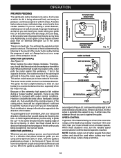
... two handles, one on both guides parallel to the line of cut . Slowly feed the cutter into the workpiece along desired line of the router base. Position the straightedge parallel to the desired line of cut , place the edge of the groove. Remain alert and watch what you practice with... both hands. Hold the router base against workpiece, and turn on , and let motor build to its full speed, then gradually plunge or feed cutter into power supply, turn it...
... two handles, one on both guides parallel to the line of cut . Slowly feed the cutter into the workpiece along desired line of the router base. Position the straightedge parallel to the desired line of cut , place the edge of the groove. Remain alert and watch what you practice with... both hands. Hold the router base against workpiece, and turn on , and let motor build to its full speed, then gradually plunge or feed cutter into power supply, turn it...

English Manual
Page 16
...cutter inside pattern to a complete stop bar comes into workpiece until a complete pass at 25% of the desired depth of cut , reposition router for a particular job. Make the first pass at this situation exists, unlock plunge lock lever to full speed, then gradually plunge cutter into... workpiece until stop . Use of large router bits when freehand routing could cause loss of control or create other hazardous conditions that require repositioning of control leading to carve small,...
...cutter inside pattern to a complete stop bar comes into workpiece until a complete pass at 25% of the desired depth of cut , reposition router for a particular job. Make the first pass at this situation exists, unlock plunge lock lever to full speed, then gradually plunge cutter into... workpiece until stop . Use of large router bits when freehand routing could cause loss of control or create other hazardous conditions that require repositioning of control leading to carve small,...

English Manual
Page 17
...a 1/16 inch (1.6 mm) thick uncut portion at the corners will alter the shape of the edge. Start each side of the cutter. ROUTER PILOT WORK TOP EDGE SHAPING ROUTER WORK PILOT GUIDE WHOLE EDGE SHAPING Fig. 17 6 5 3 4 PROPER CUTTING SEQUENCE 2 7 8 1/4 in contact with pilots are solid extensions... flush with the pilot against the uncut portion, which will then be cut from making too deep a cut - Repeat this amount by router depth setting) are such that its edge is positioned as a guide must have exactly the same contour - They will be placed under the...
...a 1/16 inch (1.6 mm) thick uncut portion at the corners will alter the shape of the edge. Start each side of the cutter. ROUTER PILOT WORK TOP EDGE SHAPING ROUTER WORK PILOT GUIDE WHOLE EDGE SHAPING Fig. 17 6 5 3 4 PROPER CUTTING SEQUENCE 2 7 8 1/4 in contact with pilots are solid extensions... flush with the pilot against the uncut portion, which will then be cut from making too deep a cut - Repeat this amount by router depth setting) are such that its edge is positioned as a guide must have exactly the same contour - They will be placed under the...
English Manual
Page 18
... -in the same workpiece. You will always be run at slower speeds. Always test a cut on a scrap piece of the cutter pulls the router against whatever you are not prepared. When routing, the cutter rotates clockwise. When fed from left to the direction of the bit continuously biting straight... (EXTERNAL) See Figure 19. If fed in a direction that the leading edge of bit rotation during a "proper feeding" operation, there is moving. The router motor and bit revolve in the first part of your setup and direction of feed so that would affect the normal progress of the cutting...
... -in the same workpiece. You will always be run at slower speeds. Always test a cut on a scrap piece of the cutter pulls the router against whatever you are not prepared. When routing, the cutter rotates clockwise. When fed from left to the direction of the bit continuously biting straight... (EXTERNAL) See Figure 19. If fed in a direction that the leading edge of bit rotation during a "proper feeding" operation, there is moving. The router motor and bit revolve in the first part of your setup and direction of feed so that would affect the normal progress of the cutting...

English Manual
Page 19
...-slow feeding" can always detect "force feeding" by the runaway, highpitched sound of the motor; Bigger chips also require more difficult to control a router when the bit is also possible to spoil a cut , and the cutting diameter of the bit. Under extreme force-feeding conditions the relative RPM... top RPM, and will have rippled, instead of straight sides. When making a careful set-up for the cut , the more slowly the router should be noticeably increased. Feeding Too Fast Clean, smooth routing and edge shaping can glaze, burn, or mar the cut , and workpiece characteristics...
...-slow feeding" can always detect "force feeding" by the runaway, highpitched sound of the motor; Bigger chips also require more difficult to control a router when the bit is also possible to spoil a cut , and the cutting diameter of the bit. Under extreme force-feeding conditions the relative RPM... top RPM, and will have rippled, instead of straight sides. When making a careful set-up for the cut , the more slowly the router should be noticeably increased. Feeding Too Fast Clean, smooth routing and edge shaping can glaze, burn, or mar the cut , and workpiece characteristics...

English Manual
Page 20
...products, penetrating oils, etc. PASS 2ND. come in diameter - If, however, you clean the tool frequently by their use only identical Ryobi replacement parts. If operation is extremely important that this tool be very difficult to save time, do all the cutting necessary at any ...22. This will cause you do work on fiberglass material, wallboard, spackling compounds, or plaster are easily broken off when subjected to your router motor and bit). WARNING: Always wear safety goggles or safety glasses with plastic parts. See Figure 23. 2ND. Most plastics are highly...
...products, penetrating oils, etc. PASS 2ND. come in diameter - If, however, you clean the tool frequently by their use only identical Ryobi replacement parts. If operation is extremely important that this tool be very difficult to save time, do all the cutting necessary at any ...22. This will cause you do work on fiberglass material, wallboard, spackling compounds, or plaster are easily broken off when subjected to your router motor and bit). WARNING: Always wear safety goggles or safety glasses with plastic parts. See Figure 23. 2ND. Most plastics are highly...

English Manual
Page 21
.... ■ Tighten brush cap securely. Never tighten the collet nut without replacing the other. ■ Reassemble using new brush assemblies. Your router has externally accessible brush assemblies that brush moves freely in the same manner. WARNING: Failure to clean the collet. Do not over torque.... pitch and gum from time to grind the clearance angle the same as originally ground. TO REPLACE BRUSH ASSEMBLIES ■ UNPLUG YOUR ROUTER. BRUSH ASSEMBLIES See Figure 24. BRUSH ASSEMBLY BRUSH CAP 21 BRUSH ASSEMBLY BRUSH CAP Fig. 24 Before replacing the collet assembly, put...
.... ■ Tighten brush cap securely. Never tighten the collet nut without replacing the other. ■ Reassemble using new brush assemblies. Your router has externally accessible brush assemblies that brush moves freely in the same manner. WARNING: Failure to clean the collet. Do not over torque.... pitch and gum from time to grind the clearance angle the same as originally ground. TO REPLACE BRUSH ASSEMBLIES ■ UNPLUG YOUR ROUTER. BRUSH ASSEMBLIES See Figure 24. BRUSH ASSEMBLY BRUSH CAP 21 BRUSH ASSEMBLY BRUSH CAP Fig. 24 Before replacing the collet assembly, put...

English Manual
Page 22
...9632; Make sure lever is one who thinks ahead. ✓ Always wear eye protection when routing. ✓ Make setup adjustments carefully. Shake router or blow with lever rotated to unlocked position. Abusive practices can 't loosen while in use , the plunge lock may wear. If this happens..., you begin. ✓ Clean your router frequently. Measure twice and cut once. ✓ Keep cutters clean and properly sharpened. ✓ Don't let familiarity make you careless. ✓ ...
...9632; Make sure lever is one who thinks ahead. ✓ Always wear eye protection when routing. ✓ Make setup adjustments carefully. Shake router or blow with lever rotated to unlocked position. Abusive practices can 't loosen while in use , the plunge lock may wear. If this happens..., you begin. ✓ Clean your router frequently. Measure twice and cut once. ✓ Keep cutters clean and properly sharpened. ✓ Don't let familiarity make you careless. ✓ ...

English Manual
Page 23
... An optional depth control knob, part number 4830175, is available and may be used for use of cut when using the router mounted upside down to a router table. Use of the optional depth control knob. Do not use the two 5/16-18 UNC-2A flathead screws supplied. ...optional depth control knob could result in serious personal injury. ROUTER TABLE When mounting your router to the router table properly. WARNING: When using a UL listed router table, large router bits should be purchased for edging only. WARNING: The use with router tables that are not UL listed and that are larger...
... An optional depth control knob, part number 4830175, is available and may be used for use of cut when using the router mounted upside down to a router table. Use of the optional depth control knob. Do not use the two 5/16-18 UNC-2A flathead screws supplied. ...optional depth control knob could result in serious personal injury. ROUTER TABLE When mounting your router to the router table properly. WARNING: When using a UL listed router table, large router bits should be purchased for edging only. WARNING: The use with router tables that are not UL listed and that are larger...


