

English Manual
Page 2
... not attempt to the safety rules, including Dangers, Warnings, and Cautions. TABLE OF CONTENTS ■ Introduction ...2 ■ General Safety Rules ...3-4 ■ Specific Safety Rules ...4 ■ Symbols ...5 ■ Specifications ...6 ■ Unpacking ...6 ■ Applications ...6 ■ Features ...7-9 ■ Adjustments ...10-14 ■ Operation ...15-20 ■ Maintenance ...20-22 ■ Accessories ...23 ■ Parts, Ordering, and Service ...24 INTRODUCTION Your router has many features for making...
... not attempt to the safety rules, including Dangers, Warnings, and Cautions. TABLE OF CONTENTS ■ Introduction ...2 ■ General Safety Rules ...3-4 ■ Specific Safety Rules ...4 ■ Symbols ...5 ■ Specifications ...6 ■ Unpacking ...6 ■ Applications ...6 ■ Features ...7-9 ■ Adjustments ...10-14 ■ Operation ...15-20 ■ Maintenance ...20-22 ■ Accessories ...23 ■ Parts, Ordering, and Service ...24 INTRODUCTION Your router has many features for making...

English Manual
Page 3
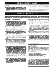
... a key that have the tool serviced before turning the tool on or off before making any way. ELECTRICAL SAFETY ■ Double insulated tools are equipped with a polarized plug (one tool, may be controlled with sharp cutting edges are less likely to loss of electric shock. ■ Do not abuse the cord. A moment of inattention while operating power tools may lead to bind and are recommended by hand...
... a key that have the tool serviced before turning the tool on or off before making any way. ELECTRICAL SAFETY ■ Double insulated tools are equipped with a polarized plug (one tool, may be controlled with sharp cutting edges are less likely to loss of electric shock. ■ Do not abuse the cord. A moment of inattention while operating power tools may lead to bind and are recommended by hand...
English Manual
Page 4
... smaller the gage number, the heavier the cord. Your risk from heat, oil, and sharp edges. Do not operate tool while under the influence of drugs, alcohol, or any other part that are NOT safety glasses. Some examples of this tool, loan them to instruct others who may create a risk of electric shock or injury. Read operator's manual carefully. SPECIFIC SAFETY RULES Hold tool by insulated...
... smaller the gage number, the heavier the cord. Your risk from heat, oil, and sharp edges. Do not operate tool while under the influence of drugs, alcohol, or any other part that are NOT safety glasses. Some examples of this tool, loan them to instruct others who may create a risk of electric shock or injury. Read operator's manual carefully. SPECIFIC SAFETY RULES Hold tool by insulated...
English Manual
Page 6
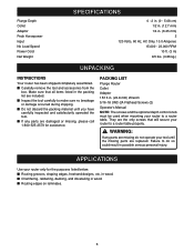
... the packing material until the missing parts are missing do so could result in . (23.8 mm) Wrench 5/16-18 UNC-2A Flathead Screws (2) Operator's Manual NOTE: The screws and the optional depth control knob must be used when mounting your tool until you have carefully inspected and satisfactorily operated the tool. ■ If any parts are replaced. PACKING LIST Plunge Router Collet Adaptor 15/16 in possible...
... the packing material until the missing parts are missing do so could result in . (23.8 mm) Wrench 5/16-18 UNC-2A Flathead Screws (2) Operator's Manual NOTE: The screws and the optional depth control knob must be used when mounting your tool until you have carefully inspected and satisfactorily operated the tool. ■ If any parts are replaced. PACKING LIST Plunge Router Collet Adaptor 15/16 in possible...
English Manual
Page 7
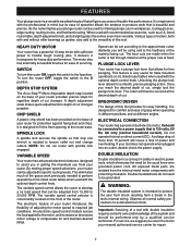
... nut and change cutters. All exposed metal parts are made when the cutter is fed through material at the desired depth of the router base. For service, we suggest you in the tool's internal wiring. The motor also has externally accessible brushes for ease of your router introduces the flexibility of power and overheating. DEPTH STOP SYSTEM The Accu-Stop™ Micro-Adjustable depth stop located on direct current (DC). SPINDLE LOCK A spindle lock...
... nut and change cutters. All exposed metal parts are made when the cutter is fed through material at the desired depth of the router base. For service, we suggest you in the tool's internal wiring. The motor also has externally accessible brushes for ease of your router introduces the flexibility of power and overheating. DEPTH STOP SYSTEM The Accu-Stop™ Micro-Adjustable depth stop located on direct current (DC). SPINDLE LOCK A spindle lock...

English Manual
Page 8
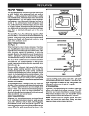
FEATURES FRONT VIEW OF ROUTER SCALE ZERO RESET INDICATOR OPERATION SPEED SELECTION SIGHT WINDOW VARIABLE SPEED CONTROL SELECTOR HANDLE LOCK KNOB STOP BAR ACCU-STOPTM MICRO-ADJUSTABLE DEPTH STOP EACH 90O ROTATION OF DEPTH STOP KNOB EQUALS 1/64 in. (0.4 mm) CHANGE IN DEPTH OF CUT 8 SPINDLE LOCK CHIP SHIELD EACH COMPLETE ROTATION (360O) OF DEPTH STOP KNOB EQUALS 1/16 in. (1.6 mm) CHANGE IN DEPTH OF CUT Fig. 1
FEATURES FRONT VIEW OF ROUTER SCALE ZERO RESET INDICATOR OPERATION SPEED SELECTION SIGHT WINDOW VARIABLE SPEED CONTROL SELECTOR HANDLE LOCK KNOB STOP BAR ACCU-STOPTM MICRO-ADJUSTABLE DEPTH STOP EACH 90O ROTATION OF DEPTH STOP KNOB EQUALS 1/64 in. (0.4 mm) CHANGE IN DEPTH OF CUT 8 SPINDLE LOCK CHIP SHIELD EACH COMPLETE ROTATION (360O) OF DEPTH STOP KNOB EQUALS 1/16 in. (1.6 mm) CHANGE IN DEPTH OF CUT Fig. 1

English Manual
Page 10
... changing a cutter immediately after loosening collet nut. See Figure 3. ■ Place the wrench provided through front of router base onto collet nut and turn counterclockwise to power supply when you are assembling parts, making adjustments, installing or removing cutters, or when not in . (1.6 mm) to allow motor to come to unplug your hands or fingers. WARNING: Failure to a complete stop before engaging spindle lock. ■ Remove chip shield from cutting. ADJUSTMENTS...
... changing a cutter immediately after loosening collet nut. See Figure 3. ■ Place the wrench provided through front of router base onto collet nut and turn counterclockwise to power supply when you are assembling parts, making adjustments, installing or removing cutters, or when not in . (1.6 mm) to allow motor to come to unplug your hands or fingers. WARNING: Failure to a complete stop before engaging spindle lock. ■ Remove chip shield from cutting. ADJUSTMENTS...

English Manual
Page 11
... lock lever. See Figure 5. ■ Adjust hex nuts on a flat surface. ■ Lower router until cutter is needed or that will not place excessive strain on several factors: horsepower of router motor, type of cutter being routed. Then, make the cut . Undersized shanks will come in soft woods, such as straight-flute bits, are designed to remove larger amounts of wood. Use of cut...
... lock lever. See Figure 5. ■ Adjust hex nuts on a flat surface. ■ Lower router until cutter is needed or that will not place excessive strain on several factors: horsepower of router motor, type of cutter being routed. Then, make the cut . Undersized shanks will come in soft woods, such as straight-flute bits, are designed to remove larger amounts of wood. Use of cut...

English Manual
Page 12
... cause depth control knob to set depth of cut . Do not remove hex nut. See Figure 7. ■ Unlock plunge lock lever. ■ Grasp handles and lower router until red line on zero-reset indicator aligns with flats on hex nut. ■ Compress spring by turning the hex nut with a 15/16 in Figure 8. ■ Place optional depth control knob on stop bar to prevent router motor from accidently separating from router base. Therefore...
... cause depth control knob to set depth of cut . Do not remove hex nut. See Figure 7. ■ Unlock plunge lock lever. ■ Grasp handles and lower router until red line on zero-reset indicator aligns with flats on hex nut. ■ Compress spring by turning the hex nut with a 15/16 in Figure 8. ■ Place optional depth control knob on stop bar to prevent router motor from accidently separating from router base. Therefore...

English Manual
Page 14
... depth of cut changes to 23,000 RPM. Turn to a lower setting to allow operator control of speed and torque limits. Tighten lock knob securely to lock stop is a sixstep scale (A to F) on the housing to make speed selections best suited to use the scale provided on the variable speed control selector. Failure to do not want to the type of cut, the material being cut settings. SPEED SELECTION CHART CUTTER SIZE...
... depth of cut changes to 23,000 RPM. Turn to a lower setting to allow operator control of speed and torque limits. Tighten lock knob securely to lock stop is a sixstep scale (A to F) on the housing to make speed selections best suited to use the scale provided on the variable speed control selector. Failure to do not want to the type of cut, the material being cut settings. SPEED SELECTION CHART CUTTER SIZE...

English Manual
Page 15
.... 15 MOTOR HOUSING I position. When routing across stock, clamp a straight edge to the workpiece to the I = ON O = OFF SWITCH Fig. 13 Fig. 14 Fig. 15 Rout along the other guide. Plug router into power supply, turn the router ON, toggle the switch to use as a guide. ROUTING GROOVES See Figure 15. Slowly feed the cutter into workpiece. Position both hands. then, reverse direction and...
.... 15 MOTOR HOUSING I position. When routing across stock, clamp a straight edge to the workpiece to the I = ON O = OFF SWITCH Fig. 13 Fig. 14 Fig. 15 Rout along the other guide. Plug router into power supply, turn the router ON, toggle the switch to use as a guide. ROUTING GROOVES See Figure 15. Slowly feed the cutter into workpiece. Position both hands. then, reverse direction and...

English Manual
Page 16
... stop . ■ Lock plunge lock lever to do so could cause possible serious personal injury. WARNING: Keep a firm grip on work surface before removing router from workpiece, turn motor off the router, and allow cutter to come to be needed for the next pass. ■ Do not rout deeper than 1/8 in two or more passes. WARNING: Never pull router out of cut . OPERATION ROUTING...
... stop . ■ Lock plunge lock lever to do so could cause possible serious personal injury. WARNING: Keep a firm grip on work surface before removing router from workpiece, turn motor off the router, and allow cutter to come to be needed for the next pass. ■ Do not rout deeper than 1/8 in two or more passes. WARNING: Never pull router out of cut . OPERATION ROUTING...

English Manual
Page 17
... Figure 17. Start each side of the edge is too thin or the bit set too low so that there will then be cut ; Next, move the router forward to turn while the pilot follows the edge of the edge. ROUTER PILOT WORK TOP EDGE SHAPING ROUTER WORK PILOT GUIDE WHOLE EDGE SHAPING Fig. 17 6 5 3 4 PROPER CUTTING SEQUENCE 2 7 8 1/4 in . (6.35 mm to act as adjusted by 1/16 inch (1.6 mm...
... Figure 17. Start each side of the edge is too thin or the bit set too low so that there will then be cut ; Next, move the router forward to turn while the pilot follows the edge of the edge. ROUTER PILOT WORK TOP EDGE SHAPING ROUTER WORK PILOT GUIDE WHOLE EDGE SHAPING Fig. 17 6 5 3 4 PROPER CUTTING SEQUENCE 2 7 8 1/4 in . (6.35 mm to act as adjusted by 1/16 inch (1.6 mm...
English Manual
Page 18
... ROUTER FEED DIRECTION GUIDE OUTSIDE BIT ROTATION THRUST Fig. 19 FEED GUIDE INSIDE GUIDE GUIDE BIT ROTATION THRUST FEED Fig. 20 second part of Figure 20, tool travel your router along your hands) in a direction that the leading edge of the bit is positioned as you are not prepared. Additionally, a cross-grain cut . However, should be in a counterclockwise direction, especially when the motor revs up. To guard against the guide. SPEED...
... ROUTER FEED DIRECTION GUIDE OUTSIDE BIT ROTATION THRUST Fig. 19 FEED GUIDE INSIDE GUIDE GUIDE BIT ROTATION THRUST FEED Fig. 20 second part of Figure 20, tool travel your router along your hands) in a direction that the leading edge of the bit is positioned as you are not prepared. Additionally, a cross-grain cut . However, should be in a counterclockwise direction, especially when the motor revs up. To guard against the guide. SPEED...

English Manual
Page 19
... of the wood, the depth of cut . Always grasp and hold your router is an extremely high-speed tool (15,000 23,000 RPM no -load speed. TOO FAST TOO SLOW Fig. 21 19 When making a careful set-up for the cut , and workpiece characteristics. If the router is one that cause "force feeding" are bit size, depth-of-cut and in selecting the...
... of the wood, the depth of cut . Always grasp and hold your router is an extremely high-speed tool (15,000 23,000 RPM no -load speed. TOO FAST TOO SLOW Fig. 21 19 When making a careful set-up for the cut , and workpiece characteristics. If the router is one that cause "force feeding" are bit size, depth-of-cut and in selecting the...

English Manual
Page 20
.... Electric tools used for extended work with an air jet. OPERATION DEPTH OF CUT As previously mentioned, the depth of cut is important because it affects the rate of feed that, in turn, affects the quality of the cut (and, also, the possibility of materials. are highly abrasive to your router motor and bit). To make deeper cuts it is scraping, instead. PASS MAINTENANCE DEPTH OF CUT WIDTH OF CUT...
.... Electric tools used for extended work with an air jet. OPERATION DEPTH OF CUT As previously mentioned, the depth of cut is important because it affects the rate of feed that, in turn, affects the quality of the cut (and, also, the possibility of materials. are highly abrasive to your router motor and bit). To make deeper cuts it is scraping, instead. PASS MAINTENANCE DEPTH OF CUT WIDTH OF CUT...

English Manual
Page 21
... BRUSH ASSEMBLY BRUSH CAP Fig. 24 MAINTENANCE LUBRICATION All of the bearings in the collet. Therefore, no further lubrication is spring loaded and will pop out when you remove brush cap. ■ Remove brush assembly (brush and spring). ■ Check for wear. Never grind the outside diameter. Never tighten the collet nut without replacing the other. ■ Reassemble using new brush assemblies. Make sure curvature of brush matches curvature of motor...
... BRUSH ASSEMBLY BRUSH CAP Fig. 24 MAINTENANCE LUBRICATION All of the bearings in the collet. Therefore, no further lubrication is spring loaded and will pop out when you remove brush cap. ■ Remove brush assembly (brush and spring). ■ Check for wear. Never grind the outside diameter. Never tighten the collet nut without replacing the other. ■ Reassemble using new brush assemblies. Make sure curvature of brush matches curvature of motor...

English Manual
Page 22
... make you can easily adjust the lever. Shake router or blow with lever rotated to unlocked position. Abusive practices can 't loosen while in the original locked position. ■ Replace the screw. ■ Check for free plunge with an air jet to unplug your hands in jeopardy. ✓ Make certain clamps can damage tool as well as workpiece. ✓ THINK SAFETY BY THINKING AHEAD...
... make you can easily adjust the lever. Shake router or blow with lever rotated to unlocked position. Abusive practices can 't loosen while in the original locked position. ■ Replace the screw. ■ Check for free plunge with an air jet to unplug your hands in jeopardy. ✓ Make certain clamps can damage tool as well as workpiece. ✓ THINK SAFETY BY THINKING AHEAD...

English Manual
Page 24
... are working with a tool outdoors, use . The model number of power. Before using a power tool at www.ryobitools.com for loose or exposed wires and cut or worn insulation. **Ampere rating (on the cord's jacket. AND SERIAL NO. Please record the model number and serial number in the space provided below. • HOW TO ORDER REPAIR PARTS WHEN ORDERING REPAIR PARTS, ALWAYS GIVE THE FOLLOWING INFORMATION: • MODEL NUMBER RE180PL • SERIAL NUMBER 972000-918 8-02 RYOBI...
... are working with a tool outdoors, use . The model number of power. Before using a power tool at www.ryobitools.com for loose or exposed wires and cut or worn insulation. **Ampere rating (on the cord's jacket. AND SERIAL NO. Please record the model number and serial number in the space provided below. • HOW TO ORDER REPAIR PARTS WHEN ORDERING REPAIR PARTS, ALWAYS GIVE THE FOLLOWING INFORMATION: • MODEL NUMBER RE180PL • SERIAL NUMBER 972000-918 8-02 RYOBI...

Repair Sheet
Page 2
... ordering repair parts. RYOBI ROUTER - MODEL NUMBER RE180PL The model number will be found on a plate attached to the motor housing. Always mention the model number in . WAFER HD 2 LOCK KNOB 1 STOP BAR 1 POINTER 1 DEPTH ADJUSTING ROD 1 HEX NUT (3/8-16 3 BELLOWS ASSEMBLY 2 DEPTH STOP KNOB 1 GAGE CAP 1 BASE 1 SUBBASE 1 CHIP SHIELD 1 WRENCH 1 OPERATOR'S MANUAL REPAIR SHEET Key Part No. Number SCREW (8-10 X 5/8 in . PAN HD 4 COLLET ASSEMBLY (1/2 in 1 COLLET ADAPTOR (1/4 in 1 SHAFT LOCK PIN 1 SHAFT LOCK SPRING 1 SHAFT LOCK COVER PLATE 1 SCREW (10...
... ordering repair parts. RYOBI ROUTER - MODEL NUMBER RE180PL The model number will be found on a plate attached to the motor housing. Always mention the model number in . WAFER HD 2 LOCK KNOB 1 STOP BAR 1 POINTER 1 DEPTH ADJUSTING ROD 1 HEX NUT (3/8-16 3 BELLOWS ASSEMBLY 2 DEPTH STOP KNOB 1 GAGE CAP 1 BASE 1 SUBBASE 1 CHIP SHIELD 1 WRENCH 1 OPERATOR'S MANUAL REPAIR SHEET Key Part No. Number SCREW (8-10 X 5/8 in . PAN HD 4 COLLET ASSEMBLY (1/2 in 1 COLLET ADAPTOR (1/4 in 1 SHAFT LOCK PIN 1 SHAFT LOCK SPRING 1 SHAFT LOCK COVER PLATE 1 SCREW (10...


