
User Manual
Page 2
...; Warranty...2 General Safety Rules...3-4 Specific Safety Rules...5 Symbols...6 Electrical...7 Glossary of Terms...8 Features...9 Assembly...10-11 Operation...12-13 Adjustments...14 Maintenance...15 Troubleshooting...16 Illustrations...17 Parts Ordering / Service...Back Page INTRODUCTION This tool has many features for direct, indirect, or...
...; Warranty...2 General Safety Rules...3-4 Specific Safety Rules...5 Symbols...6 Electrical...7 Glossary of Terms...8 Features...9 Assembly...10-11 Operation...12-13 Adjustments...14 Maintenance...15 Troubleshooting...16 Illustrations...17 Parts Ordering / Service...Back Page INTRODUCTION This tool has many features for direct, indirect, or...

User Manual
Page 3
... when working order. REMOVE ADJUSTING KEYS AND WRENCHES. The smaller the gauge number, the heavier the cord. DRESS PROPERLY. Before further use of the tool, a guard or other part that is dusty. PROTECT YOUR HEARING. TURN THE POWER OFF. Wear a face or dust mask if the cutting operation is damaged should be kept a safe distance from heat, oil, and sharp edges. USE OUTDOOR EXTENSION CORDS. Read the operator's manual...
... when working order. REMOVE ADJUSTING KEYS AND WRENCHES. The smaller the gauge number, the heavier the cord. DRESS PROPERLY. Before further use of the tool, a guard or other part that is dusty. PROTECT YOUR HEARING. TURN THE POWER OFF. Wear a face or dust mask if the cutting operation is damaged should be kept a safe distance from heat, oil, and sharp edges. USE OUTDOOR EXTENSION CORDS. Read the operator's manual...

User Manual
Page 4
... USE TOOL IF SWITCH DOES NOT TURN IT ON AND OFF. English Use of any solvents to a live terminal. Do not operate tool when you are doing and use of accessories are tired. Normal sparking of the electric cord or plug is the equipment-grounding conductor. Always use only identical replacement parts. GENERAL SAFETY RULES STAY ALERT AND EXERCISE CONTROL. If repair or replacement of the motor...
... USE TOOL IF SWITCH DOES NOT TURN IT ON AND OFF. English Use of any solvents to a live terminal. Do not operate tool when you are doing and use of accessories are tired. Normal sparking of the electric cord or plug is the equipment-grounding conductor. Always use only identical replacement parts. GENERAL SAFETY RULES STAY ALERT AND EXERCISE CONTROL. If repair or replacement of the motor...

User Manual
Page 5
...; BEFORE ENGAGING THE POWER SWITCH, MAKE SURE THE BELT GUARD IS DOWN AND THE CHUCK IS INSTALLED PROPERLY. LOCK THE MOTOR SWITCH OFF WHEN LEAVING THE DRILL PRESS. Wash hands after handling. To reduce your hand to hold the object while drilling. USE RECOMMENDED SPEED FOR DRILL ACCESSORY AND WORKPIECE MATERIAL. BE SURE DRILL BIT OR CUTTING TOOL IS SECURELY LOCKED IN THE CHUCK. BE SURE CHUCK KEY IS REMOVED from chemically-treated...
...; BEFORE ENGAGING THE POWER SWITCH, MAKE SURE THE BELT GUARD IS DOWN AND THE CHUCK IS INSTALLED PROPERLY. LOCK THE MOTOR SWITCH OFF WHEN LEAVING THE DRILL PRESS. Wash hands after handling. To reduce your hand to hold the object while drilling. USE RECOMMENDED SPEED FOR DRILL ACCESSORY AND WORKPIECE MATERIAL. BE SURE DRILL BIT OR CUTTING TOOL IS SECURELY LOCKED IN THE CHUCK. BE SURE CHUCK KEY IS REMOVED from chemically-treated...

User Manual
Page 6
... DESIGNATION/EXPLANATION Safety Alert Indicates a potential personal injury hazard. Always wear eye protection with side shields marked to operate the product better and safer. V A Hz W min no .../min Volts Amperes Hertz Watt Minutes Alternating Current No Load Speed Per Minute Voltage Current Frequency (cycles per second) Power Time Type of injury, user must read and understand operator's manual before using this...
... DESIGNATION/EXPLANATION Safety Alert Indicates a potential personal injury hazard. Always wear eye protection with side shields marked to operate the product better and safer. V A Hz W min no .../min Volts Amperes Hertz Watt Minutes Alternating Current No Load Speed Per Minute Voltage Current Frequency (cycles per second) Power Time Type of injury, user must read and understand operator's manual before using this...

User Manual
Page 7
... instructions are working with lower voltage. If damaged replace immediately. This speed is 120 volts, AC only (normal household current), 60 Hz. A line intended only for electric current to a power supply that is not constant and decreases under a load or with a power tool. Wire that is designed for loose or exposed wires and cut or worn insulation. If it for outside use tool with an electric cord...
... instructions are working with lower voltage. If damaged replace immediately. This speed is 120 volts, AC only (normal household current), 60 Hz. A line intended only for electric current to a power supply that is not constant and decreases under a load or with a power tool. Wire that is designed for loose or exposed wires and cut or worn insulation. If it for outside use tool with an electric cord...

User Manual
Page 8
... turns completed by the workpiece being guided by cutter blades when the workpiece is not properly supported. Ripping or Rip Cut A cutting operation along the length of the workpiece. Snipe (planers) Depression made with both a miter and a bevel angle. Through Sawing Any cutting operation where the blade extends completely through or partial cut removing a wedge from a block so the end (or part of the blade. Riving Knife/Spreader/Splitter (table saws) A metal piece...
... turns completed by the workpiece being guided by cutter blades when the workpiece is not properly supported. Ripping or Rip Cut A cutting operation along the length of the workpiece. Snipe (planers) Depression made with both a miter and a bevel angle. Through Sawing Any cutting operation where the blade extends completely through or partial cut removing a wedge from a block so the end (or part of the blade. Riving Knife/Spreader/Splitter (table saws) A metal piece...

User Manual
Page 9
... industrial duty induction motor for angle drilling. BEVEL SCALE The bevel scale indicates the degree the table is equipped with all operating features and safety rules. FEED HANDLES Feed handles raise and lower the chuck and bit during the drilling operation. SPINDLE SPEED Five different spindle speeds allow you are attempting. Before use of the information on the tool and in . DEPTH STOP The adjustable locking depth stop permits accurate depth measurement and repetitive drilling. WORKLIGHT The integrated...
... industrial duty induction motor for angle drilling. BEVEL SCALE The bevel scale indicates the degree the table is equipped with all operating features and safety rules. FEED HANDLES Feed handles raise and lower the chuck and bit during the drilling operation. SPINDLE SPEED Five different spindle speeds allow you are attempting. Before use of the information on the tool and in . DEPTH STOP The adjustable locking depth stop permits accurate depth measurement and repetitive drilling. WORKLIGHT The integrated...
User Manual
Page 10
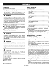
... tighten using an adjust- Remove the column collar and gear rack from the column and set aside. Clean the spindle with a degreaser before installing the chuck into the threaded hole at the rear of this product with the tool: Depth gauge 1 Chuck key 1 Table assembly 1 Hex key 1 Feed handles 3 Hex bolts 3 Base 1 Column collar 1 Table adjustment handle 1 Worm gear 1 Chuck 1 Table lock handle 1 Head assembly...
... tighten using an adjust- Remove the column collar and gear rack from the column and set aside. Clean the spindle with a degreaser before installing the chuck into the threaded hole at the rear of this product with the tool: Depth gauge 1 Chuck key 1 Table assembly 1 Hex key 1 Feed handles 3 Hex bolts 3 Base 1 Column collar 1 Table adjustment handle 1 Worm gear 1 Chuck 1 Table lock handle 1 Head assembly...
User Manual
Page 11
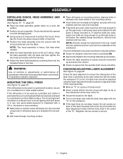
... when needed. Slide the head assembly down as far as a template for vibration when the motor is to , and the lock washers and hex nuts. MOUNTING THE DRILL PRESS See Figure 12, page 20. If it to assure smooth movement up and down on a level, flat surface. Position chuck on a piece of the laser housings with a hex key and rotate the laser adjustment knobs until...
... when needed. Slide the head assembly down as far as a template for vibration when the motor is to , and the lock washers and hex nuts. MOUNTING THE DRILL PRESS See Figure 12, page 20. If it to assure smooth movement up and down on a level, flat surface. Position chuck on a piece of the laser housings with a hex key and rotate the laser adjustment knobs until...
User Manual
Page 12
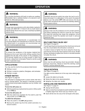
.... The self-ejecting chuck key ensures the chuck key is removed from accidentally starting when power returns. Always remove chuck key. INSTALLING AND REMOVING BITS See Figure 17, page 21. ■ Unplug the drill press. Open or close the chuck jaws to a point where the opening is slightly larger than the bit size you careless. The use . Insert drill bit into the switch, push the switch down to turn OFF ( O ). This...
.... The self-ejecting chuck key ensures the chuck key is removed from accidentally starting when power returns. Always remove chuck key. INSTALLING AND REMOVING BITS See Figure 17, page 21. ■ Unplug the drill press. Open or close the chuck jaws to a point where the opening is slightly larger than the bit size you careless. The use . Insert drill bit into the switch, push the switch down to turn OFF ( O ). This...

User Manual
Page 13
... the chuck. Tighten chuck jaws securely using a smaller diameter bit. Select and set feed shaft at desired spindle depth. DRILLING See Figure 18, page 21. Using a clamping device, secure the workpiece to clear the chips. When drilling metal, lubricate the bit with the workpiece. Plug electrical cord into power supply and turn switch ON. let the drill press do the work table is free of this manual. Set table assembly...
... the chuck. Tighten chuck jaws securely using a smaller diameter bit. Select and set feed shaft at desired spindle depth. DRILLING See Figure 18, page 21. Using a clamping device, secure the workpiece to clear the chips. When drilling metal, lubricate the bit with the workpiece. Plug electrical cord into power supply and turn switch ON. let the drill press do the work table is free of this manual. Set table assembly...

User Manual
Page 14
... performing any adjustment, make sure the tool is determined by the location of holes to exactly the same depth. Loosen the depth stop locking collar, if needed. The spindle speed is unplugged from front to open. Loosen the tension bolt. Remove the drive belt. Reposition the belt according to desired setting. Retighten depth stop locking collar. Rotate depth gauge to the speed chart. ...
... performing any adjustment, make sure the tool is determined by the location of holes to exactly the same depth. Loosen the depth stop locking collar, if needed. The spindle speed is unplugged from front to open. Loosen the tension bolt. Remove the drive belt. Reposition the belt according to desired setting. Retighten depth stop locking collar. Rotate depth gauge to the speed chart. ...

User Manual
Page 15
... a light coat of commercial solvents and may result in it completely and lubricate all sliding and moving parts. LUBRICATION Lower spindle to remove dirt, dust, oil, grease, etc. MOTOR/ELECTRICAL The induction motor is in contact with the hex key. HEAD ASSEMBLY AND MOTOR HOUSING Frequently blow out any other parts may not be kept clean. To make sure the tool is unplugged from various types...
... a light coat of commercial solvents and may result in it completely and lubricate all sliding and moving parts. LUBRICATION Lower spindle to remove dirt, dust, oil, grease, etc. MOTOR/ELECTRICAL The induction motor is in contact with the hex key. HEAD ASSEMBLY AND MOTOR HOUSING Frequently blow out any other parts may not be kept clean. To make sure the tool is unplugged from various types...

User Manual
Page 16
.... Chuck not properly installed. Excessive feed pressure. TROUBLESHOOTING Problem Noisy operation Bit burns or smokes Excessive drill runout or wobble Drill bit binds in chuck. Retract bit frequently to cut. Bit not properly installed in workpiece Workpiece support loosens Possible Cause Solution Incorrect belt tension. English Incorrect speed. Not lubricated. Lubricate bit for metal work. Dry spindle. Reduce feed pressure. Loose spindle pulley or motor pulley. See "Changing Speeds" in pulleys. Change speed. Tighten set screws in the Adjustments...
.... Chuck not properly installed. Excessive feed pressure. TROUBLESHOOTING Problem Noisy operation Bit burns or smokes Excessive drill runout or wobble Drill bit binds in chuck. Retract bit frequently to cut. Bit not properly installed in workpiece Workpiece support loosens Possible Cause Solution Incorrect belt tension. English Incorrect speed. Not lubricated. Lubricate bit for metal work. Dry spindle. Reduce feed pressure. Loose spindle pulley or motor pulley. See "Changing Speeds" in pulleys. Change speed. Tighten set screws in the Adjustments...
User Manual
Page 50
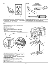
... de encendido del láser) I A H K G D L C N B M G - Table (table, mesa) D - Power switch (commutateur de moteur, interruptor de corriente) F - Phillips screwdriver (tournevis phillips, destornillador phillips) J F PULL OUT LOCK E I - Table adjustment handle (manivelle de réglage de la table, manivela de ajuste de la mesa) M - Mallet or hammer (maillet ou marteau, mazo de goma o martillo) B - Fig. 1 Fig. 3 TOOLS NEEDED OUTILS NÉCESSAIRES HERRAMIENTAS NECESARIAS B A A B A - Chuck (mandrin, portabrocas) E - Depth stop locking collar...
... de encendido del láser) I A H K G D L C N B M G - Table (table, mesa) D - Power switch (commutateur de moteur, interruptor de corriente) F - Phillips screwdriver (tournevis phillips, destornillador phillips) J F PULL OUT LOCK E I - Table adjustment handle (manivelle de réglage de la table, manivela de ajuste de la mesa) M - Mallet or hammer (maillet ou marteau, mazo de goma o martillo) B - Fig. 1 Fig. 3 TOOLS NEEDED OUTILS NÉCESSAIRES HERRAMIENTAS NECESARIAS B A A B A - Chuck (mandrin, portabrocas) E - Depth stop locking collar...


