
User Manual
Page 2
... balance at the rate for outdoor use . If damaged, have the switch on . Properly maintained cutting tools with 18V nickel-cadmium and 18V lithium-ion battery packs, see tool/appliance/battery pack/charger correlation supplement 987000-432. ELECTRICAL SAFETY Power tool plugs must be drawn into air vents. Do not use a ground fault circuit interrupter (GFCI) protected supply. Use of a cord suitable for which may result...
... balance at the rate for outdoor use . If damaged, have the switch on . Properly maintained cutting tools with 18V nickel-cadmium and 18V lithium-ion battery packs, see tool/appliance/battery pack/charger correlation supplement 987000-432. ELECTRICAL SAFETY Power tool plugs must be drawn into air vents. Do not use a ground fault circuit interrupter (GFCI) protected supply. Use of a cord suitable for which may result...
User Manual
Page 3
... less than 100°F. This will reduce the risk of unauthorized parts or failure to be plugged into your battery tool should be ejected from those intended could give the operator an electric shock. Know your hearing. Use of electric shock. For best results, your eyes, flush them these instructions. GENERAL POWER TOOL SAFETY WARNINGS Use the power tool, accessories and tool bits etc.
... less than 100°F. This will reduce the risk of unauthorized parts or failure to be plugged into your battery tool should be ejected from those intended could give the operator an electric shock. Know your hearing. Use of electric shock. For best results, your eyes, flush them these instructions. GENERAL POWER TOOL SAFETY WARNINGS Use the power tool, accessories and tool bits etc.
User Manual
Page 4
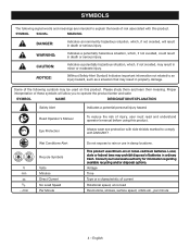
... with this product. Read Operator's Manual To reduce the risk of batteries in minor or moderate injury. Local, state or federal laws may prohibit disposal of injury, user must read and understand operator's manual before using this product. Consult your ...EXPLANATION Safety Alert Indicates a potential personal injury hazard. Some of risk associated with ANSI Z87.1. This product uses lithium-ion or nickel-cadmium batteries. Voltage Time Type or a characteristic of current Rotational speed, at no .../min Recycle Symbols Volts Minutes Direct Current No Load Speed Per...
... with this product. Read Operator's Manual To reduce the risk of batteries in minor or moderate injury. Local, state or federal laws may prohibit disposal of injury, user must read and understand operator's manual before using this product. Consult your ...EXPLANATION Safety Alert Indicates a potential personal injury hazard. Some of risk associated with ANSI Z87.1. This product uses lithium-ion or nickel-cadmium batteries. Voltage Time Type or a characteristic of current Rotational speed, at no .../min Recycle Symbols Volts Minutes Direct Current No Load Speed Per...
User Manual
Page 5
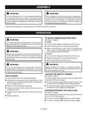
... gun ON, depress the switch trigger. To turn the caulk gun OFF, release the switch trigger. 5 - English Therefore, the switch should always be locked when not in use or carrying at your eyes, resulting in possible serious injury. WARNING: Do not attempt to make you careless. TO INSTALL/REMOVE BATTERY PACK See Figure 1, page 9. To install: Lock the switch trigger by sliding the switch lock up . Insert the battery...
... gun ON, depress the switch trigger. To turn the caulk gun OFF, release the switch trigger. 5 - English Therefore, the switch should always be locked when not in use or carrying at your eyes, resulting in possible serious injury. WARNING: Do not attempt to make you careless. TO INSTALL/REMOVE BATTERY PACK See Figure 1, page 9. To install: Lock the switch trigger by sliding the switch lock up . Insert the battery...
User Manual
Page 6
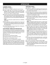
... the spout on the tube, the motor will create a clean, finished appearance. Use a damp towel or rag to remove any dust, dirt, or remnants of caulk you continue to be less likely to provide a larger opening. OPERATION LOADING CAULK See Figures 3 - 4, page 9. Lock the switch trigger by sliding the switch lock up. Using a utility knife, cut off , make sure that: ...
... the spout on the tube, the motor will create a clean, finished appearance. Use a damp towel or rag to remove any dust, dirt, or remnants of caulk you continue to be less likely to provide a larger opening. OPERATION LOADING CAULK See Figures 3 - 4, page 9. Lock the switch trigger by sliding the switch lock up. Using a utility knife, cut off , make sure that: ...
User Manual
Page 7
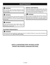
WARNING: To avoid serious personal injury, always remove the battery pack from various types of commercial solvents and may be damaged by their use only identical replacement parts. WARNING: Do not at any time let brake fluids, gasoline, petroleumbased products, penetrating oils, etc., come in possible serious injury. MAINTENANCE WARNING: When servicing, use . NOTE: ILLUSTRATIONS START ON PAGE 9 AFTER FRENCH AND SPANISH...
WARNING: To avoid serious personal injury, always remove the battery pack from various types of commercial solvents and may be damaged by their use only identical replacement parts. WARNING: Do not at any time let brake fluids, gasoline, petroleumbased products, penetrating oils, etc., come in possible serious injury. MAINTENANCE WARNING: When servicing, use . NOTE: ILLUSTRATIONS START ON PAGE 9 AFTER FRENCH AND SPANISH...
User Manual 2
Page 3
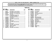
.... MODEL NUMBER P310G The model number will be found on a label attached to the motor housing. Hd 1 Pin 1 Rack Handle 1 Screw (M5 x 15 mm, Pan Hd 1 Trigger Lock Button 1 Motor Cover 1 Screw (M3 x 4 mm, Pan Hd 1 18 830235001 Power Mosfet 1 19 631289001 Heat Sink 1 20 342787005 Speed Control Dial Knob 1 21 940114194 Logo Label 1 22 760307001 Switch 1 23 512905001 Field 1 24 810203001 Speed Potentiometer 1 25 300001044 Contact Plate Holder 1 26...
.... MODEL NUMBER P310G The model number will be found on a label attached to the motor housing. Hd 1 Pin 1 Rack Handle 1 Screw (M5 x 15 mm, Pan Hd 1 Trigger Lock Button 1 Motor Cover 1 Screw (M3 x 4 mm, Pan Hd 1 18 830235001 Power Mosfet 1 19 631289001 Heat Sink 1 20 342787005 Speed Control Dial Knob 1 21 940114194 Logo Label 1 22 760307001 Switch 1 23 512905001 Field 1 24 810203001 Speed Potentiometer 1 25 300001044 Contact Plate Holder 1 26...
User Manual 2
Page 5
...) PARTS LIST DESCRIPTION QTY C-Ring...2 Shift Gear...2 Gear Case Assembly...1 Carrier...1 Planetary Gear ...6 Solar Gear...1 Gear Train Housing Assembly 1 Washer...1 Screw (M3 x 6 mm, Pan Hd 2 Spring Washer...2 Motor Bracket...1 Screw (M3 x 16 mm, Pan Hd 6 Motor Assembly...1 Gear Housing Cover Assembly 1 Gear...1 Ring Gear...1 Carrier Shaft...1 Planetary Gear...6 Spring...1 Clutch ...1 Ring Gear...1 Solar Gear...1 Gear Shaft...1 Washer...1 Operator's Manual (961152325) 5 KEY NO. MODEL NUMBER P310G The model number will be found on a label attached to the motor housing. RYOBI 18 VOLT...
...) PARTS LIST DESCRIPTION QTY C-Ring...2 Shift Gear...2 Gear Case Assembly...1 Carrier...1 Planetary Gear ...6 Solar Gear...1 Gear Train Housing Assembly 1 Washer...1 Screw (M3 x 6 mm, Pan Hd 2 Spring Washer...2 Motor Bracket...1 Screw (M3 x 16 mm, Pan Hd 6 Motor Assembly...1 Gear Housing Cover Assembly 1 Gear...1 Ring Gear...1 Carrier Shaft...1 Planetary Gear...6 Spring...1 Clutch ...1 Ring Gear...1 Solar Gear...1 Gear Shaft...1 Washer...1 Operator's Manual (961152325) 5 KEY NO. MODEL NUMBER P310G The model number will be found on a label attached to the motor housing. RYOBI 18 VOLT...
User Manual 2
Page 6
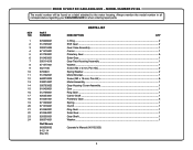
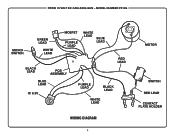
RYOBI 18 VOLT DC CAULKING GUN - MODEL NUMBER P310G MICRO SWITCH GREEN LEAD WHITE LEAD MOSFET PURPLE LEAD WHITE LEAD BLUE LEAD RED LEAD BLACK LEAD PCB ASSEMBLY BLUE LEAD IC 6.2V PURPLE LEAD BLACK LEAD WHITE LEAD WIRING DIAGRAM 6 MOTOR SWITCH RED LEAD CONTACT PLATE HOLDER
RYOBI 18 VOLT DC CAULKING GUN - MODEL NUMBER P310G MICRO SWITCH GREEN LEAD WHITE LEAD MOSFET PURPLE LEAD WHITE LEAD BLUE LEAD RED LEAD BLACK LEAD PCB ASSEMBLY BLUE LEAD IC 6.2V PURPLE LEAD BLACK LEAD WHITE LEAD WIRING DIAGRAM 6 MOTOR SWITCH RED LEAD CONTACT PLATE HOLDER


