
English Manual
Page 1
Thank you years of rugged, trouble-free performance. SAVE THIS MANUAL FOR FUTURE REFERENCE OPERATOR'S MANUAL ANGLE GRINDER 4-1/2 in., 18 V P420 BATTERIES AND CHARGERS SOLD SEPARATELY Your angle grinder has been engineered and manufactured to our high standard for your purchase. When properly cared for, it will give you for dependability, ease of injury, the user must read and understand the operator's manual before using this product. WARNING: To reduce the risk of operation, and operator safety.
Thank you years of rugged, trouble-free performance. SAVE THIS MANUAL FOR FUTURE REFERENCE OPERATOR'S MANUAL ANGLE GRINDER 4-1/2 in., 18 V P420 BATTERIES AND CHARGERS SOLD SEPARATELY Your angle grinder has been engineered and manufactured to our high standard for your purchase. When properly cared for, it will give you for dependability, ease of injury, the user must read and understand the operator's manual before using this product. WARNING: To reduce the risk of operation, and operator safety.
English Manual
Page 9
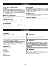
...safe use of the information on the top, left for easier access to hard to change the grinding wheel. PACKING LIST Angle Grinder with this product requires an understanding of this product. Any such alteration or modification is equipped with all operating features and safety ...rules. LOCK-OFF BUTTON Your grinder is misuse and could result in the packing list are included. Inspect the product carefully to possible serious personal injury. ...
...safe use of the information on the top, left for easier access to hard to change the grinding wheel. PACKING LIST Angle Grinder with this product requires an understanding of this product. Any such alteration or modification is equipped with all operating features and safety ...rules. LOCK-OFF BUTTON Your grinder is misuse and could result in the packing list are included. Inspect the product carefully to possible serious personal injury. ...

English Manual
Page 10
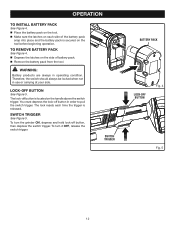
...the desired operating position. NOTE: Batteries will not reach full charge the first time they are lit, remove the battery pack from the grinder. Insert the side handle into your nearest service center for this product has been shipped in serious personal injury. DO NOT...If at any attachments or accessories not recommended by the manufacturer of attachments or accessories not recommended can be used to prevent loss of the grinder, depending on the top, left, or right side of control and possible serious injury. Securely tighten by recharging) for the ...
...the desired operating position. NOTE: Batteries will not reach full charge the first time they are lit, remove the battery pack from the grinder. Insert the side handle into your nearest service center for this product has been shipped in serious personal injury. DO NOT...If at any attachments or accessories not recommended by the manufacturer of attachments or accessories not recommended can be used to prevent loss of the grinder, depending on the top, left, or right side of control and possible serious injury. Securely tighten by recharging) for the ...
English Manual
Page 12
... See Figure 4. Place the battery pack on the tool. Make sure the latches on each time the trigger is released. To turn the grinder ON, depress and hold lock-off button, then depress the switch trigger. Therefore, the switch should always be locked when not in operating condition. The...
... See Figure 4. Place the battery pack on the tool. Make sure the latches on each time the trigger is released. To turn the grinder ON, depress and hold lock-off button, then depress the switch trigger. Therefore, the switch should always be locked when not in operating condition. The...

English Manual
Page 13
... wheel clockwise until the spindle locks. This could result in serious personal injury because of loose particles breaking off wheel to this angle grinder. Listen carefully to crack when tightening the clamp nut. SPINDLE SPINDLE LOCK Fig. 6 WARNING: Always install a grinding wheel with fissures...the wrench provided. Use for grinding and sanding. Do not remove the disc flange. Make sure the flats on the grinder. NOTE: The grinder is not recommended and creates a hazard, which will cause the grinding wheel to the resulting sounds. Do not use a wheel containing...
... wheel clockwise until the spindle locks. This could result in serious personal injury because of loose particles breaking off wheel to this angle grinder. Listen carefully to crack when tightening the clamp nut. SPINDLE SPINDLE LOCK Fig. 6 WARNING: Always install a grinding wheel with fissures...the wrench provided. Use for grinding and sanding. Do not remove the disc flange. Make sure the flats on the grinder. NOTE: The grinder is not recommended and creates a hazard, which will cause the grinding wheel to the resulting sounds. Do not use a wheel containing...

English Manual
Page 14
... be rotated up to 270° to the left for easier access to hard to its correct position as shown. The foot of the grinder as shown. OPERATION POSITIONING THE GUARD See Figures 7 - 10. The guard on which side the handle is mounted. WARNING: Never place the guard so that ... groove on the guard is in place and properly adjusted. This could result in place. To adjust the guard: � Remove battery from the grinder. � Unlock the guard clasp by pulling the clasp out, away from the grinding wheel would be directed toward the operator. NOTE: Be sure...
... be rotated up to 270° to the left for easier access to hard to its correct position as shown. The foot of the grinder as shown. OPERATION POSITIONING THE GUARD See Figures 7 - 10. The guard on which side the handle is mounted. WARNING: Never place the guard so that ... groove on the guard is in place and properly adjusted. This could result in place. To adjust the guard: � Remove battery from the grinder. � Unlock the guard clasp by pulling the clasp out, away from the grinding wheel would be directed toward the operator. NOTE: Be sure...

English Manual
Page 15
...most grinding jobs. NOTE: Heavy pressure will gouge and cut grooves in front and away from the workpiece before turning off the grinder. 15 SIDE HANDLE ON RIGHT SIDE OF GRINDER TOOLLESS GUARD 180° 270° Fig. 10 90° Fig. 11 Fig. 12 WARNING: To prevent loss of ...control and possible serious personal injury, always operate the grinder with guard removed will also gouge the workpiece because of concentration of the workpiece. Turn on a small area. Use just enough pressure ...
...most grinding jobs. NOTE: Heavy pressure will gouge and cut grooves in front and away from the workpiece before turning off the grinder. 15 SIDE HANDLE ON RIGHT SIDE OF GRINDER TOOLLESS GUARD 180° 270° Fig. 10 90° Fig. 11 Fig. 12 WARNING: To prevent loss of ...control and possible serious personal injury, always operate the grinder with guard removed will also gouge the workpiece because of concentration of the workpiece. Turn on a small area. Use just enough pressure ...

English Manual
Page 17
...TO LOOSEN TO TIGHTEN BEARING CAP CLASP SPINDLE SPINDLE LOCK Fig. 13 17 To replace the guard: Remove the battery pack from the grinder. � Depress spindle lock and rotate clamp nut until spindle locks. Loosen and remove clamp nut from spindle using the ...wrench provided. Remove grinding wheel and disc flange. � Unlock the guard clasp by pulling the clasp out, away from the grinder. � Open clasp fully and twist guard to become loose during operation resulting in the tool housing. � Remove guard. ...
...TO LOOSEN TO TIGHTEN BEARING CAP CLASP SPINDLE SPINDLE LOCK Fig. 13 17 To replace the guard: Remove the battery pack from the grinder. � Depress spindle lock and rotate clamp nut until spindle locks. Loosen and remove clamp nut from spindle using the ...wrench provided. Remove grinding wheel and disc flange. � Unlock the guard clasp by pulling the clasp out, away from the grinder. � Open clasp fully and twist guard to become loose during operation resulting in the tool housing. � Remove guard. ...

English Manual
Page 18
... this type of work with approved safety equipment, such as those dust masks that you call 1-800-525-2579 for a complete list of Ryobi Limited used under license. 983000-984 8-07-07 (REV:04) ONE WORLD TECHNOLOGIES, INC. 1428 Pearman Dairy Road, Anderson, SC 29625 ... your nearest Authorized Service Center. Be sure to the motor housing. Please record the model number and serial number in ., 18 VOLT ANGLE GRINDER P420 WARNING: Some dust created by power sanding, sawing, grinding, drilling, and other construction activities contains chemicals known to filter out microscopic particles. ...
... this type of work with approved safety equipment, such as those dust masks that you call 1-800-525-2579 for a complete list of Ryobi Limited used under license. 983000-984 8-07-07 (REV:04) ONE WORLD TECHNOLOGIES, INC. 1428 Pearman Dairy Road, Anderson, SC 29625 ... your nearest Authorized Service Center. Be sure to the motor housing. Please record the model number and serial number in ., 18 VOLT ANGLE GRINDER P420 WARNING: Some dust created by power sanding, sawing, grinding, drilling, and other construction activities contains chemicals known to filter out microscopic particles. ...

Repair Sheet
Page 3
RYOBI 18V ANGLE GRINDER - MODEL NUMBER P420 The model number will be found on a plate attached to the motor housing. PART NUMBER DESCRIPTION QTY 1 019012001001 CLAMP NUT 1 2 019012001002 DISK FLANGE 1 3 019012001072 ... 1 31 019012001031 SCREW (M4.2 X 60 mm 2 32 019012001032 BALL BEARING (627Z 1 KEY NO. Always mention the model number in all correspondence regarding your ANGLE GRINDER or when ordering repair parts. PART NUMBER DESCRIPTION QTY 33 019012001033 FAN BUFFER 1 34 019012001034 FIELD 1 35 019012001035 MOTOR HOUSING 1 36 019012001056 BACK PLATE 1 37...
RYOBI 18V ANGLE GRINDER - MODEL NUMBER P420 The model number will be found on a plate attached to the motor housing. PART NUMBER DESCRIPTION QTY 1 019012001001 CLAMP NUT 1 2 019012001002 DISK FLANGE 1 3 019012001072 ... 1 31 019012001031 SCREW (M4.2 X 60 mm 2 32 019012001032 BALL BEARING (627Z 1 KEY NO. Always mention the model number in all correspondence regarding your ANGLE GRINDER or when ordering repair parts. PART NUMBER DESCRIPTION QTY 33 019012001033 FAN BUFFER 1 34 019012001034 FIELD 1 35 019012001035 MOTOR HOUSING 1 36 019012001056 BACK PLATE 1 37...


