
English Manual
Page 3
... of starting . n Do not operate power tools in unexpected situations. This plug will increase the risk of electric shock. Carrying tools with a polarized plug (one blade is off . n Do not overreach. Proper footing and balance enables better control of flammable liquids, gases, or dust. Accessories that have the tool serviced before...
... of starting . n Do not operate power tools in unexpected situations. This plug will increase the risk of electric shock. Carrying tools with a polarized plug (one blade is off . n Do not overreach. Proper footing and balance enables better control of flammable liquids, gases, or dust. Accessories that have the tool serviced before...
English Manual
Page 5
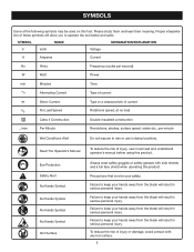
...of these symbols will result in serious personal injury. Failure to keep your hands away from the blade will result in damp locations. Failure to keep your hands away from the blade will allow you to rain or use in serious personal injury. To reduce the risk of ... characteristic of the following symbols may be used on this tool. Precautions that involve your hands away from the blade will result in serious personal injury. Failure to keep your hands away from the blade will result in serious personal injury. Please study them and learn their meaning.
...of these symbols will result in serious personal injury. Failure to keep your hands away from the blade will result in damp locations. Failure to keep your hands away from the blade will allow you to rain or use in serious personal injury. To reduce the risk of ... characteristic of the following symbols may be used on this tool. Precautions that involve your hands away from the blade will result in serious personal injury. Failure to keep your hands away from the blade will result in serious personal injury. Please study them and learn their meaning.
English Manual
Page 8
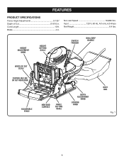
HEIGHT ADJUSTMENT KNOB HEIGHT SETTING SCALE SWITCH TRIGGER DUAL GRIP HANDLE WIDTH OF CUT SCALE CENTERLINE/LINE OF CUT INDICATOR ADJUSTABLE FENCE NON-SKID SURFACE ANGLE SETTING SCALE DEPTH ADJUSTMENT KNOB LOCKING KNOB DUST BAG Fig. 1 8 No Load Speed 10,000/min. Blade 4 in . Cord Length 10 ft. Input 120 V, 60 Hz, AC only, 6.0 Amps Net Weight 8.4 lbs. FEATURES PRODUCT SPECIFICATIONS Fence Angle Adjustments 0-135° Depth of Cut 0-9/16 in .
HEIGHT ADJUSTMENT KNOB HEIGHT SETTING SCALE SWITCH TRIGGER DUAL GRIP HANDLE WIDTH OF CUT SCALE CENTERLINE/LINE OF CUT INDICATOR ADJUSTABLE FENCE NON-SKID SURFACE ANGLE SETTING SCALE DEPTH ADJUSTMENT KNOB LOCKING KNOB DUST BAG Fig. 1 8 No Load Speed 10,000/min. Blade 4 in . Cord Length 10 ft. Input 120 V, 60 Hz, AC only, 6.0 Amps Net Weight 8.4 lbs. FEATURES PRODUCT SPECIFICATIONS Fence Angle Adjustments 0-135° Depth of Cut 0-9/16 in .
English Manual
Page 9
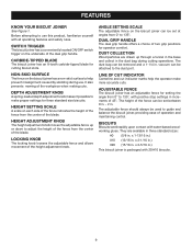
... a conveniently located ON/OFF switch trigger on the biscuit joiner can be attached to 135°. CARBIDE-TIPPED BLADE The biscuit joiner has an 8-tooth carbide-tipped blade for three standard size biscuits. DUAL GRIP HANDLE The dual grip handle offers a choice of the height adjustment ... The locking knob loosens the adjustable fence and allows movement of two grip positions for setting the angle from the center of the blade. ADJUSTABLE FENCE The biscuit joiner has an adjustable fence for operator comfort. HEIGHT ADJUSTMENT KNOB The height adjustment knob moves the adjustable ...
... a conveniently located ON/OFF switch trigger on the biscuit joiner can be attached to 135°. CARBIDE-TIPPED BLADE The biscuit joiner has an 8-tooth carbide-tipped blade for three standard size biscuits. DUAL GRIP HANDLE The dual grip handle offers a choice of the height adjustment ... The locking knob loosens the adjustable fence and allows movement of two grip positions for setting the angle from the center of the blade. ADJUSTABLE FENCE The biscuit joiner has an adjustable fence for operator comfort. HEIGHT ADJUSTMENT KNOB The height adjustment knob moves the adjustable ...
English Manual
Page 13
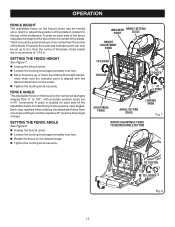
... adjustment knob until the indicator point is located on each side of the fence indicates the height of the fence from the center of the blade. from the center of 1/16 in 45° increments. n Loosen the locking knob approximately one turn . INDICATOR POINT HEIGHT SETTING SCALE HEIGHT ... the locking knob securely. FENCE ANGLE The adjustable fence on the biscuit joiner can be moved up or down to adjust the position of the blade in . n Rotate the fence to another equals a 45° positive stop angle change. OPERATION FENCE HEIGHT The adjustable fence on the biscuit ...
... adjustment knob until the indicator point is located on each side of the fence indicates the height of the fence from the center of the blade. from the center of 1/16 in 45° increments. n Loosen the locking knob approximately one turn . INDICATOR POINT HEIGHT SETTING SCALE HEIGHT ... the locking knob securely. FENCE ANGLE The adjustable fence on the biscuit joiner can be moved up or down to adjust the position of the blade in . n Rotate the fence to another equals a 45° positive stop angle change. OPERATION FENCE HEIGHT The adjustable fence on the biscuit ...
English Manual
Page 14
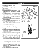
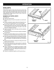
... you are planning to make the first cut in each joint lines up . n Loosen the locking knob approximately one of the workpieces. The blade will be assembled. n Set the fence height at 90°. Make sure each slot. Also, spread a bead of glue over the entire... Reinsert the biscuits and assemble the workpieces. n Unplug the biscuit joiner. n Clamp the workpiece securely so that it forward to extend the blade into the power supply and prepare to use multiple biscuits placed close together. The joint will retract from the same workpiece if possible. n Select...
... you are planning to make the first cut in each joint lines up . n Loosen the locking knob approximately one of the workpieces. The blade will be assembled. n Set the fence height at 90°. Make sure each slot. Also, spread a bead of glue over the entire... Reinsert the biscuits and assemble the workpieces. n Unplug the biscuit joiner. n Clamp the workpiece securely so that it forward to extend the blade into the power supply and prepare to use multiple biscuits placed close together. The joint will retract from the same workpiece if possible. n Select...
English Manual
Page 15
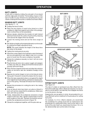
..., then push it is identical to the desired offset and cut in the procedures for cutting butt joints. n Depress the switch trigger to extend the blade into a power supply and prepare to make your first cut adjustment knob setting, pull back to be assembled. n Repeat this type of the rails...., disassemble the workpieces and place a bead of cut the slots in which they will retract from the front of the blade. MAKING BUTT JOINTS See Figures 11 - 12. The blade will be joined on this procedure for cutting offset butt joints is necessary to cut the slots in . offset is desired...
..., then push it is identical to the desired offset and cut in the procedures for cutting butt joints. n Depress the switch trigger to extend the blade into a power supply and prepare to make your first cut adjustment knob setting, pull back to be assembled. n Repeat this type of the rails...., disassemble the workpieces and place a bead of cut the slots in which they will retract from the front of the blade. MAKING BUTT JOINTS See Figures 11 - 12. The blade will be joined on this procedure for cutting offset butt joints is necessary to cut the slots in . offset is desired...
English Manual
Page 17
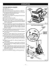
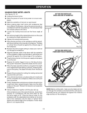
... flush against the depth of the vertical board and parallel with the centerline on the vertical board and securely clamp it down to extend the blade into the power supply and prepare to use. Also, spread a bead of glue over the entire surface of wood on the vertical board. n ... angle at the desired dimension on the base assembly with the centerline. n Cut each joint lines up . This piece of cut the slot. The blade will retract from the biscuit slot. n Select the correct depth of wood is used for cutting all slots have been cut adjustment knob setting, pull...
... flush against the depth of the vertical board and parallel with the centerline on the vertical board and securely clamp it down to extend the blade into the power supply and prepare to use. Also, spread a bead of glue over the entire surface of wood on the vertical board. n ... angle at the desired dimension on the base assembly with the centerline. n Cut each joint lines up . This piece of cut the slot. The blade will retract from the biscuit slot. n Select the correct depth of wood is used for cutting all slots have been cut adjustment knob setting, pull...
English Manual
Page 18
... to use, and clamp the workpiece securely. n Place the pieces of wood to turn on the scale, select the correct depth of the wood. The blade will retract from the biscuit slot. Reinsert the biscuits and assemble the workpieces. Edge miters are used when making picture frames. MAKING FLAT MITER JOINTS... the fence angle at 90°, set the fence height at the desired dimension on the biscuit joiner, then push it forward to extend the blade into the power supply and prepare to cut setting for cutting the mating slot and all slots have been cut adjustment knob setting, pull back...
... to use, and clamp the workpiece securely. n Place the pieces of wood to turn on the scale, select the correct depth of the wood. The blade will retract from the biscuit slot. Reinsert the biscuits and assemble the workpieces. Edge miters are used when making picture frames. MAKING FLAT MITER JOINTS... the fence angle at 90°, set the fence height at the desired dimension on the biscuit joiner, then push it forward to extend the blade into the power supply and prepare to cut setting for cutting the mating slot and all slots have been cut adjustment knob setting, pull back...
English Manual
Page 19
... scale by rotating the height adjustment knob. n Mark the centerline of glue in each slot. n Depress the switch trigger to extend the blade into the power supply and prepare to cut through the workpiece. n Repeat this procedure for cutting the mating slot and all slots have different... bead of glue over the entire surface of workpiece. n Tighten the locking knob securely. n Recheck the fence height setting to make sure the blade will not cut adjustment knob setting, pull back, releasing pressure on each joint lines up . Make sure the base or vertical fence is pressed ...
... scale by rotating the height adjustment knob. n Mark the centerline of glue in each slot. n Depress the switch trigger to extend the blade into the power supply and prepare to cut through the workpiece. n Repeat this procedure for cutting the mating slot and all slots have different... bead of glue over the entire surface of workpiece. n Tighten the locking knob securely. n Recheck the fence height setting to make sure the blade will not cut adjustment knob setting, pull back, releasing pressure on each joint lines up . Make sure the base or vertical fence is pressed ...
English Manual
Page 20
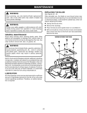
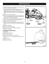
...of the bearings in this tool for the life of high grade lubricant for extended work on these materials, it will require replacing the blade. After extended use . n Remove the dust bag. Most plastics are highly abrasive to bearings, brushes, commutators, etc. Chemicals can ... normal operating conditions. Therefore, no further lubrication is dusty, also wear a dust mask. MAINTENANCE WARNING: When servicing, use only identical Ryobi replacement parts. WARNING: Do not at any other blunt object, it is extremely important to damage from various types of any time let...
...of the bearings in this tool for the life of high grade lubricant for extended work on these materials, it will require replacing the blade. After extended use . n Remove the dust bag. Most plastics are highly abrasive to bearings, brushes, commutators, etc. Chemicals can ... normal operating conditions. Therefore, no further lubrication is dusty, also wear a dust mask. MAINTENANCE WARNING: When servicing, use only identical Ryobi replacement parts. WARNING: Do not at any other blunt object, it is extremely important to damage from various types of any time let...

English Manual
Page 21
.... SCREWDRIVER NON-CUTTING TOOTH BEHIND CARBIDE-TIPPED CUTTING TOOTH HEX KEY BLADE BLADE SCREW OUTER BLADE WASHER BLADE Fig. 23 BLADE SCREW INNER BLADE WASHER GEAR SPINDLE Fig. 24 21 hex key, remove the blade screw. NOTE: Turn the blade screw counterclockwise to prevent it from the blade washers, dust bag area, base assembly, and all surrounding parts. n Place...
.... SCREWDRIVER NON-CUTTING TOOTH BEHIND CARBIDE-TIPPED CUTTING TOOTH HEX KEY BLADE BLADE SCREW OUTER BLADE WASHER BLADE Fig. 23 BLADE SCREW INNER BLADE WASHER GEAR SPINDLE Fig. 24 21 hex key, remove the blade screw. NOTE: Turn the blade screw counterclockwise to prevent it from the blade washers, dust bag area, base assembly, and all surrounding parts. n Place...
English Manual
Page 22
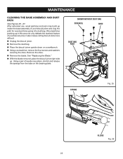
... the path for wood particles going into dust bag. n Remove the dust bag. n Unplug the biscuit joiner. Remove the shoe. n With the blade removed, place the biscuit joiner right side up in this area not only defeats the dustless feature of your biscuit joiner, it also makes cutting...slots more difficult. Wood particles packing up . SHOWN WITHOUT DUST BAG SCREW(S) SHOE DUST BAG PORT SPRING Fig. 25 PLIERS Fig. 26 22 n Remove the blade. Using a pair of needle nose pliers, stretch and release the springs from the tabs on a workbench. n Using a screwdriver, remove the four screws ...
... the path for wood particles going into dust bag. n Remove the dust bag. n Unplug the biscuit joiner. Remove the shoe. n With the blade removed, place the biscuit joiner right side up in this area not only defeats the dustless feature of your biscuit joiner, it also makes cutting...slots more difficult. Wood particles packing up . SHOWN WITHOUT DUST BAG SCREW(S) SHOE DUST BAG PORT SPRING Fig. 25 PLIERS Fig. 26 22 n Remove the blade. Using a pair of needle nose pliers, stretch and release the springs from the tabs on a workbench. n Using a screwdriver, remove the four screws ...
English Manual
Page 23
...where the assemblies meet. Replace and tighten the screws that connect the front and rear base assemblies. n Replace the springs. n Reinstall or replace the blade. n Unplug the biscuit joiner. n Apply a thin coat of the dust bag. n Replace the clip. MAINTENANCE n Using a screwdriver, remove ... wood particles and resin from the rear base assembly. n Replace the rear base assembly. n Carefully separate the front base assembly from the blade area, dust bag port, front and rear assemblies and all debris. n Remove the dust bag. n Replace the front base assembly. TRACK...
...where the assemblies meet. Replace and tighten the screws that connect the front and rear base assemblies. n Replace the springs. n Reinstall or replace the blade. n Unplug the biscuit joiner. n Apply a thin coat of the dust bag. n Replace the clip. MAINTENANCE n Using a screwdriver, remove ... wood particles and resin from the rear base assembly. n Replace the rear base assembly. n Carefully separate the front base assembly from the blade area, dust bag port, front and rear assemblies and all debris. n Remove the dust bag. n Replace the front base assembly. TRACK...
English Manual
Page 24
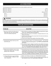
......100 pieces Size 20...200 pieces WARNING: Current attachments and accessories available for the size slots that have been cut: #0, #10, or #20. Blade does not retract properly when cutting slots. 4. Compress biscuits in a vise if they are too deep or too shallow. The dust bag may also ... or accessories not recommended can result in when cutting slots. Empty the dust bag often. A. Wood particles and resin have swelled. Replace the blade. Resin has built up on bearing plate where base slides. Biscuits do not fit the slots. Wood particles begin to back up on base ...
......100 pieces Size 20...200 pieces WARNING: Current attachments and accessories available for the size slots that have been cut: #0, #10, or #20. Blade does not retract properly when cutting slots. 4. Compress biscuits in a vise if they are too deep or too shallow. The dust bag may also ... or accessories not recommended can result in when cutting slots. Empty the dust bag often. A. Wood particles and resin have swelled. Replace the blade. Resin has built up on bearing plate where base slides. Biscuits do not fit the slots. Wood particles begin to back up on base ...
Repair Sheet
Page 3
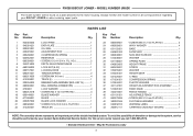
...Qty. KEY 15 1 BALL BEARING (CW#6001RS 1 LOCK WASHER 4 * SCREW (M4 X 16 mm PAN HD 4 BLADE WASHER 1 BLADE 1 BLADE LOCK WASHER 1 * SCREW (5/16-18 X 3/4 in all correspondence regarding your nearest Ryobi Authorized Service Center. FLAT HD 1 TRACK (R 1 23 660569001 24 690903001 25 631152001 26 640851003 27 900949001 28 512338001 ... you call 1-800-525-2579. * Standard Hardware Item - FIL. To avoid the possibility of the double insulated system. MODEL NUMBER JM82K The model number will be performed by your BISCUIT JOINER or when ordering repair parts. Key Part No.
...Qty. KEY 15 1 BALL BEARING (CW#6001RS 1 LOCK WASHER 4 * SCREW (M4 X 16 mm PAN HD 4 BLADE WASHER 1 BLADE 1 BLADE LOCK WASHER 1 * SCREW (5/16-18 X 3/4 in all correspondence regarding your nearest Ryobi Authorized Service Center. FLAT HD 1 TRACK (R 1 23 660569001 24 690903001 25 631152001 26 640851003 27 900949001 28 512338001 ... you call 1-800-525-2579. * Standard Hardware Item - FIL. To avoid the possibility of the double insulated system. MODEL NUMBER JM82K The model number will be performed by your BISCUIT JOINER or when ordering repair parts. Key Part No.


