
English Manual
Page 2
... after date of its power tools other than Authorized Service Centers. WHAT'S NOT COVERED: This warranty applies only to an Authorized Service Center. TABLE OF CONTENTS n Introduction ...2 n Warranty ...2 �n General Safety Rules ...3 �n Specific Safety Rules...4 �n Symbols...5-6 �n Electrical ...7 �n Features...8-9 �n Assembly ...10 �n Operation...11-19 n Adjustments...20 �n Maintenance ...20-23 n Accessories ...24 n Troubleshooting ...24 �n Parts Ordering / Service ...26 INTRODUCTION This tool has many features...
... after date of its power tools other than Authorized Service Centers. WHAT'S NOT COVERED: This warranty applies only to an Authorized Service Center. TABLE OF CONTENTS n Introduction ...2 n Warranty ...2 �n General Safety Rules ...3 �n Specific Safety Rules...4 �n Symbols...5-6 �n Electrical ...7 �n Features...8-9 �n Assembly ...10 �n Operation...11-19 n Adjustments...20 �n Maintenance ...20-23 n Accessories ...24 n Troubleshooting ...24 �n Parts Ordering / Service ...26 INTRODUCTION This tool has many features...

English Manual
Page 3
... the hands of starting . n Do not use tool while tired or under the influence of electric shock. Stable footing on a ladder or unstable support. n Do not force tool. n Disconnect the plug from heat, oil, sharp edges, or moving parts, breakage of the tool in unexpected situations. Such preventive safety measures reduce the risk of untrained users. Tools are doing and use an outdoor extension cord marked...
... the hands of starting . n Do not use tool while tired or under the influence of electric shock. Stable footing on a ladder or unstable support. n Do not force tool. n Disconnect the plug from heat, oil, sharp edges, or moving parts, breakage of the tool in unexpected situations. Such preventive safety measures reduce the risk of untrained users. Tools are doing and use an outdoor extension cord marked...
English Manual
Page 4
.... n Make sure your power tool. The smaller the gauge number, the heavier the cord. Use of unauthorized parts or failure to follow Maintenance Instructions may use this rule will reduce the risk of electric shock, fire, or serious injury. n Know your extension cord is damaged should be properly repaired or replaced by insulated gripping surfaces when performing an operation where the cutting tool may affect its applications...
.... n Make sure your power tool. The smaller the gauge number, the heavier the cord. Use of unauthorized parts or failure to follow Maintenance Instructions may use this rule will reduce the risk of electric shock, fire, or serious injury. n Know your extension cord is damaged should be properly repaired or replaced by insulated gripping surfaces when performing an operation where the cutting tool may affect its applications...
English Manual
Page 6
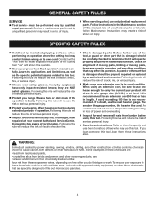
... face shield when needed. Save this product. SYMBOL SIGNAL DANGER: WARNING: CAUTION: CAUTION: MEANING Indicates an imminently hazardous situation, which is marked to use this operator's manual and review frequently for use only identical replacement parts. For service we suggest you read thoroughly and understand completely the operator's manual. We recommend Wide Vision Safety Mask for continuing safe operation and instructing others who may...
... face shield when needed. Save this product. SYMBOL SIGNAL DANGER: WARNING: CAUTION: CAUTION: MEANING Indicates an imminently hazardous situation, which is marked to use this operator's manual and review frequently for use only identical replacement parts. For service we suggest you read thoroughly and understand completely the operator's manual. We recommend Wide Vision Safety Mask for continuing safe operation and instructing others who may...
English Manual
Page 7
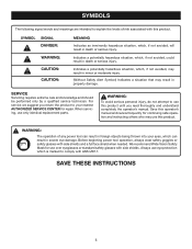
... cords before each use tool with a power tool. Double insulated tools do so can result in overheating and loss of the system and should be grounded. Observe all normal safety precautions to determine the minimum wire size required in serious injury. 7 If your nearest authorized service center for outside use original factory replacement parts when servicing. Do not operate this tool on 12 gauge - 20 amp circuit. Before using a power tool...
... cords before each use tool with a power tool. Double insulated tools do so can result in overheating and loss of the system and should be grounded. Observe all normal safety precautions to determine the minimum wire size required in serious injury. 7 If your nearest authorized service center for outside use original factory replacement parts when servicing. Do not operate this tool on 12 gauge - 20 amp circuit. Before using a power tool...
English Manual
Page 8
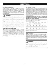
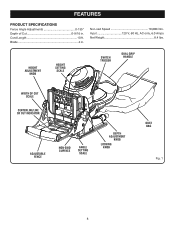
FEATURES PRODUCT SPECIFICATIONS Fence Angle Adjustments 0-135° Depth of Cut 0-9/16 in . Input 120 V, 60 Hz, AC only, 6.0 Amps Net Weight 8.4 lbs. Cord Length 10 ft. No Load Speed 10,000/min. Blade 4 in . HEIGHT ADJUSTMENT KNOB HEIGHT SETTING SCALE SWITCH TRIGGER DUAL GRIP HANDLE WIDTH OF CUT SCALE CENTERLINE/LINE OF CUT INDICATOR ADJUSTABLE FENCE NON-SKID SURFACE ANGLE SETTING SCALE DEPTH ADJUSTMENT KNOB LOCKING KNOB DUST BAG Fig. 1 8
FEATURES PRODUCT SPECIFICATIONS Fence Angle Adjustments 0-135° Depth of Cut 0-9/16 in . Input 120 V, 60 Hz, AC only, 6.0 Amps Net Weight 8.4 lbs. Cord Length 10 ft. No Load Speed 10,000/min. Blade 4 in . HEIGHT ADJUSTMENT KNOB HEIGHT SETTING SCALE SWITCH TRIGGER DUAL GRIP HANDLE WIDTH OF CUT SCALE CENTERLINE/LINE OF CUT INDICATOR ADJUSTABLE FENCE NON-SKID SURFACE ANGLE SETTING SCALE DEPTH ADJUSTMENT KNOB LOCKING KNOB DUST BAG Fig. 1 8
English Manual
Page 9
... ADJUSTMENT KNOB The height adjustment knob moves the adjustable fence up through a tunnel in the base and collect in the dust bag during use this product, familiarize yourself with positive stop settings in . DUAL GRIP HANDLE The dual grip handle offers a choice of the blade. vacuum can be set at angles from the center of two grip positions for cutting biscuit slots. The height of the blade. The adjustable fence...
... ADJUSTMENT KNOB The height adjustment knob moves the adjustable fence up through a tunnel in the base and collect in the dust bag during use this product, familiarize yourself with positive stop settings in . DUAL GRIP HANDLE The dual grip handle offers a choice of the blade. vacuum can be set at angles from the center of two grip positions for cutting biscuit slots. The height of the blade. The adjustable fence...
English Manual
Page 10
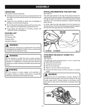
PACKING LIST Biscuit Joiner #10 Biscuits (20) Carrying Case Operator's Manual INSTALLING/REMOVING THE DUST BAG See Figure 2. To install, slide the dust bag adaptor onto the dust port on the rear of the biscuit joiner provides a dust collection system. ATTACHING THE BISCUIT JOINER TO A VACUUM See Figure 3. n Connect the biscuit joiner and the vacuum to the dust port. TO INSERT TO REMOVE Fig. 2 WARNING: Do...
PACKING LIST Biscuit Joiner #10 Biscuits (20) Carrying Case Operator's Manual INSTALLING/REMOVING THE DUST BAG See Figure 2. To install, slide the dust bag adaptor onto the dust port on the rear of the biscuit joiner provides a dust collection system. ATTACHING THE BISCUIT JOINER TO A VACUUM See Figure 3. n Connect the biscuit joiner and the vacuum to the dust port. TO INSERT TO REMOVE Fig. 2 WARNING: Do...
English Manual
Page 12
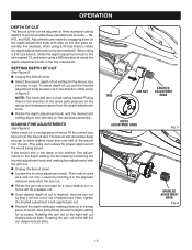
... depth adjustment knob with the tabs on the spring and releases pressure from the jam nut. SETTING DEPTH OF CUT See Figure 5. n Unplug the biscuit joiner. Pulling them in the direction of cut is used as a lock nut only. Fit the correct size biscuit into the slot. Also periodically check the depth setting for proper alignment of the arrow puts pressure on the rear base assembly. TABS JAM NUT KNURLED ADJUSTMENT KNOB DEPTH ADJUSTMENT KNOB Fig. 5 KNURLED ADJUSTMENT KNOB...
... depth adjustment knob with the tabs on the spring and releases pressure from the jam nut. SETTING DEPTH OF CUT See Figure 5. n Unplug the biscuit joiner. Pulling them in the direction of cut is used as a lock nut only. Fit the correct size biscuit into the slot. Also periodically check the depth setting for proper alignment of the arrow puts pressure on the rear base assembly. TABS JAM NUT KNURLED ADJUSTMENT KNOB DEPTH ADJUSTMENT KNOB Fig. 5 KNURLED ADJUSTMENT KNOB...
English Manual
Page 13
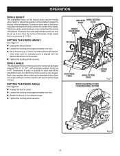
... stops set at angles ranging from 0° to two inches from the center of the workpiece. n Loosen the locking knob approximately one angle setting to the desired angle. The fence can be positioned up or down to adjust the position of the blade in relation to the top of the blade. INDICATOR POINT HEIGHT SETTING SCALE HEIGHT ADJUSTMENT KNOB TO LOWER TO RAISE TO TIGHTEN TO LOOSEN ADJUSTABLE FENCE ANGLE SETTING...
... stops set at angles ranging from 0° to two inches from the center of the workpiece. n Loosen the locking knob approximately one angle setting to the desired angle. The fence can be positioned up or down to adjust the position of the blade in relation to the top of the blade. INDICATOR POINT HEIGHT SETTING SCALE HEIGHT ADJUSTMENT KNOB TO LOWER TO RAISE TO TIGHTEN TO LOOSEN ADJUSTABLE FENCE ANGLE SETTING...
English Manual
Page 14
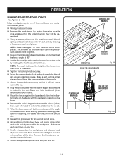
... cut adjustment knob setting, pull back, releasing pressure on the biscuit joiner, then push it will be assembled. from the center of the workpieces. NOTE: Mark the edges 2 in a scrap piece of the most basic and easilyconstructed joints. n Place the fence against the depth of the joint. The blade will be stronger if you are planning to -edge joinery is one turn on the spring...
... cut adjustment knob setting, pull back, releasing pressure on the biscuit joiner, then push it will be assembled. from the center of the workpieces. NOTE: Mark the edges 2 in a scrap piece of the most basic and easilyconstructed joints. n Place the fence against the depth of the joint. The blade will be stronger if you are planning to -edge joinery is one turn on the spring...
English Manual
Page 15
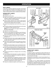
... the fence to cut setting to match the biscuit size you can create a strong joint that gives a mortise-and-tenon effect. n Loosen the locking knob and set the fence angle at the desired dimension on the spring. n When the base assembly bottoms out against the depth of cut . n Finally, disassemble the workpieces and place a bead of glue in each joint and dry-assemble the workpieces. n Using a square, determine...
... the fence to cut setting to match the biscuit size you can create a strong joint that gives a mortise-and-tenon effect. n Loosen the locking knob and set the fence angle at the desired dimension on the spring. n When the base assembly bottoms out against the depth of cut . n Finally, disassemble the workpieces and place a bead of glue in each joint and dry-assemble the workpieces. n Using a square, determine...
English Manual
Page 17
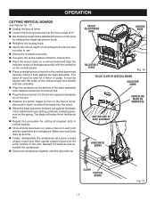
... OF BASE ASSEMBLY HORIZONTAL BOARD CLAMP VERTICAL BOARD 17 Fig. 17 OPERATION CUTTING VERTICAL BOARDS See Figures 16 - 17. n Set the fence height at the desired dimension on the bottom of cut setting for a fence or guide. n Retighten the locking knob. n Select the correct depth of wood is used for the biscuit size you plan to turn on the spring. n Cut each joint lines up . This piece of cut adjustment knob setting, pull back, releasing pressure on...
... OF BASE ASSEMBLY HORIZONTAL BOARD CLAMP VERTICAL BOARD 17 Fig. 17 OPERATION CUTTING VERTICAL BOARDS See Figures 16 - 17. n Set the fence height at the desired dimension on the bottom of cut setting for a fence or guide. n Retighten the locking knob. n Select the correct depth of wood is used for the biscuit size you plan to turn on the spring. n Cut each joint lines up . This piece of cut adjustment knob setting, pull back, releasing pressure on...
English Manual
Page 18
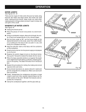
... and assemble the workpieces. n Repeat this procedure for the biscuit size you don't want to cut adjustment knob setting, pull back, releasing pressure on a level workbench. n Place the pieces of miter joints that can be joined on the spring. n Finally, disassemble the workpieces and place a bead of the wood. OPERATION MITER JOINTS See Figures 18 - 21. MAKING FLAT MITER JOINTS See Figure 18. n Using a combination square...
... and assemble the workpieces. n Repeat this procedure for the biscuit size you don't want to cut adjustment knob setting, pull back, releasing pressure on a level workbench. n Place the pieces of miter joints that can be joined on the spring. n Finally, disassemble the workpieces and place a bead of the wood. OPERATION MITER JOINTS See Figures 18 - 21. MAKING FLAT MITER JOINTS See Figure 18. n Using a combination square...
English Manual
Page 19
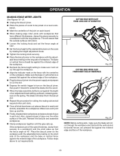
... the mitered edge of the joint. n When the base assembly bottoms out against the mitered edge and face of the joint on a level workbench. Make sure each slot. Reinsert the biscuits and assemble workpieces. Set the fence angle at 135°. n Unplug the biscuit joiner. This will assure that have been cut through the workpiece. n Recheck the fence height setting to cut adjustment knob setting, pull back, releasing pressure...
... the mitered edge of the joint. n When the base assembly bottoms out against the mitered edge and face of the joint on a level workbench. Make sure each slot. Reinsert the biscuits and assemble workpieces. Set the fence angle at 135°. n Unplug the biscuit joiner. This will assure that have been cut through the workpiece. n Recheck the fence height setting to cut adjustment knob setting, pull back, releasing pressure...
English Manual
Page 20
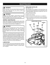
... front and rear assemblies. Therefore, no further lubrication is dusty, also wear a dust mask. Remove the shoe. Use clean cloths to bearings, brushes, commutators, etc. However, if you accidentally hit a nail or other parts may create a hazard or cause product damage. If you do not recommended using solvents when cleaning plastic parts. n With a screwdriver, remove the four screws and washers that connect the...
... front and rear assemblies. Therefore, no further lubrication is dusty, also wear a dust mask. Remove the shoe. Use clean cloths to bearings, brushes, commutators, etc. However, if you accidentally hit a nail or other parts may create a hazard or cause product damage. If you do not recommended using solvents when cleaning plastic parts. n With a screwdriver, remove the four screws and washers that connect the...

English Manual
Page 21
... cutting teeth. n Replace the washers and screws and tighten securely with the outer blade washer and the blade screw. n Using a 3/16 in the bearing plate. n Turn the blade screw clockwise and tighten securely with the hex key. n Place the inner blade washer on the gear spindle. n Place a screwdriver or pin in normal operating position. n Remove the outer blade washer, blade and inner blade washer. DO NOT lock the blade against the screwdriver or pin and lock the blade to remove the blade. Carbide tips will break. n Replace the dust...
... cutting teeth. n Replace the washers and screws and tighten securely with the outer blade washer and the blade screw. n Using a 3/16 in the bearing plate. n Turn the blade screw clockwise and tighten securely with the hex key. n Place the inner blade washer on the gear spindle. n Place a screwdriver or pin in normal operating position. n Remove the outer blade washer, blade and inner blade washer. DO NOT lock the blade against the screwdriver or pin and lock the blade to remove the blade. Carbide tips will break. n Replace the dust...
English Manual
Page 24
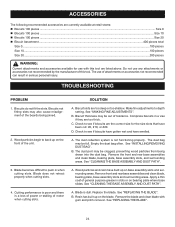
.... Blade becomes difficult to depth setting. Make fine adjustments to push in a vise if they are too thick. Empty the dust bag often. Remove the front and rear base assemblies and clean blade, bearing plate, base assembly slots, and surrounding areas. Apply a thin coat of the boards being drawn into the dust bag. See "REPLACING THE BLADE". TROUBLESHOOTING PROBLEM 1. D. The dust bag may be out of this tool are listed...
.... Blade becomes difficult to depth setting. Make fine adjustments to push in a vise if they are too thick. Empty the dust bag often. Remove the front and rear base assemblies and clean blade, bearing plate, base assembly slots, and surrounding areas. Apply a thin coat of the boards being drawn into the dust bag. See "REPLACING THE BLADE". TROUBLESHOOTING PROBLEM 1. D. The dust bag may be out of this tool are listed...
Repair Sheet
Page 3
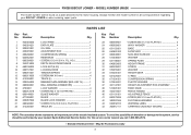
... HD 4 WAVY WASHER 4 BASE 1 FACEPLATE 1 NON-SKID SURFACE 1 WASHER 2 SPRING PLATE 2 HEIGHT FRAME 1 SCREW 2 WASHER 2 HEIGHT GEAR 2 C-RING 2 COMPRESSION SPRING 2 PLASTIC WASHER 1 HEIGHT ADJUSTMENT ROD ASSEMBLY ......... 1 FIXED KNOB 1 FENCE HANDLE 1 ADJUSTABLE FENCE 1 * SCREW (M4 X 16 mm FLAT HD 2 DUST BAG ASSEMBLY 1 WARNING LABEL 2 CARRYING CASE (NOT SHOWN 1 NOTE: The assembly shown represents an important part of alteration or damage to the motor housing. MODEL NUMBER JM82K The model number will be found on a plate attached to the system, service should be performed...
... HD 4 WAVY WASHER 4 BASE 1 FACEPLATE 1 NON-SKID SURFACE 1 WASHER 2 SPRING PLATE 2 HEIGHT FRAME 1 SCREW 2 WASHER 2 HEIGHT GEAR 2 C-RING 2 COMPRESSION SPRING 2 PLASTIC WASHER 1 HEIGHT ADJUSTMENT ROD ASSEMBLY ......... 1 FIXED KNOB 1 FENCE HANDLE 1 ADJUSTABLE FENCE 1 * SCREW (M4 X 16 mm FLAT HD 2 DUST BAG ASSEMBLY 1 WARNING LABEL 2 CARRYING CASE (NOT SHOWN 1 NOTE: The assembly shown represents an important part of alteration or damage to the motor housing. MODEL NUMBER JM82K The model number will be found on a plate attached to the system, service should be performed...
Repair Sheet
Page 5
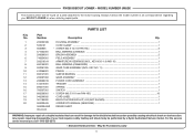
... 18 19 20 PARTS LIST Part Number 200202308 5950101 6620805 671004001 290069051 740654001 200216014 690155001 200281005 610266001 690147001 200287003 290086018 512215001 690217001 760307001 660206001 940299505 301189002 983000493 983000493R 08-24-04 Description Qty. KEY NO. 11 1 PINION ...1 SLEEVE BEARING ...1 GEAR ASSEMBLY ...1 POWER CORD ASSEMBLY ...1 TRIGGER ...1 SPRING ...1 SWITCH ...1 * SCREW (M3.5 X 18 mm PAN HD.) ...10 CORD LABEL ...1 BISCUIT ACCESSORY KIT, #10 (NOT SHOWN 1 OPERATOR'S MANUAL (960223252 1 REPAIR SHEET WARNING: Improper repair of your...
... 18 19 20 PARTS LIST Part Number 200202308 5950101 6620805 671004001 290069051 740654001 200216014 690155001 200281005 610266001 690147001 200287003 290086018 512215001 690217001 760307001 660206001 940299505 301189002 983000493 983000493R 08-24-04 Description Qty. KEY NO. 11 1 PINION ...1 SLEEVE BEARING ...1 GEAR ASSEMBLY ...1 POWER CORD ASSEMBLY ...1 TRIGGER ...1 SPRING ...1 SWITCH ...1 * SCREW (M3.5 X 18 mm PAN HD.) ...10 CORD LABEL ...1 BISCUIT ACCESSORY KIT, #10 (NOT SHOWN 1 OPERATOR'S MANUAL (960223252 1 REPAIR SHEET WARNING: Improper repair of your...


