

Operation Manual
Page 2
... state law, including warranties of this warranty. TABLE OF CONTENTS Introduction...2 Warranty...2 General Power Tool Safety Warnings...3-4 Circular Saw Safety Warnings...4-5 Symbols...6 Electrical...7 Features...8 Assembly...8-9 Operation...10-13 Adjustments...14 Maintenance...15 Accessories...16 Figure Numbers (Illustrations)...17-20 Parts Ordering / Service...Back Page INTRODUCTION This...
... state law, including warranties of this warranty. TABLE OF CONTENTS Introduction...2 Warranty...2 General Power Tool Safety Warnings...3-4 Circular Saw Safety Warnings...4-5 Symbols...6 Electrical...7 Features...8 Assembly...8-9 Operation...10-13 Adjustments...14 Maintenance...15 Accessories...16 Figure Numbers (Illustrations)...17-20 Parts Ordering / Service...Back Page INTRODUCTION This...
Operation Manual
Page 3
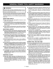
... electric shock. POWER TOOL USE AND CARE Do not force the power tool. Any power tool that have the power tool repaired before turning the power tool on a ladder or unstable support. If damaged, have the switch on a solid surface enables better control of the power tool may result in moving parts, breakage of electric shock. Do not abuse the cord. WORK AREA SAFETY Keep work area clean and well lit. Use...
... electric shock. POWER TOOL USE AND CARE Do not force the power tool. Any power tool that have the power tool repaired before turning the power tool on a ladder or unstable support. If damaged, have the switch on a solid surface enables better control of the power tool may result in moving parts, breakage of electric shock. Do not abuse the cord. WORK AREA SAFETY Keep work area clean and well lit. Use...
Operation Manual
Page 4
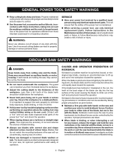
... loss of the blade, but kickback forces can be performed. CIRCULAR SAW SAFETY WARNINGS DANGER: Keep hands away from the work properly to eliminate the cause of the workpiece toward the operator. When the blade is in accordance with a "live " and shock the operator. When ripping always use only identical replacement parts. Kickback is maintained. When servicing a power tool, use a rip fence or straight edge guide. in motion or...
... loss of the blade, but kickback forces can be performed. CIRCULAR SAW SAFETY WARNINGS DANGER: Keep hands away from the work properly to eliminate the cause of the workpiece toward the operator. When the blade is in accordance with a "live " and shock the operator. When ripping always use only identical replacement parts. Kickback is maintained. When servicing a power tool, use a rip fence or straight edge guide. in motion or...
Operation Manual
Page 5
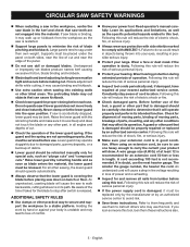
... using an extension cord, be replaced only by the manufacturer or by retracting handle and as soon as "plunge cuts" and "compound cuts." Lower guard may walk up of debris. Lower guard should operate automatically. Always observe that the lower guard is covering the blade before each use of the tool, a guard or other part, in loss of serious personal injury. Protect your power tool...
... using an extension cord, be replaced only by the manufacturer or by retracting handle and as soon as "plunge cuts" and "compound cuts." Lower guard may walk up of debris. Lower guard should operate automatically. Always observe that the lower guard is covering the blade before each use of the tool, a guard or other part, in loss of serious personal injury. Protect your power tool...

Operation Manual
Page 6
...Proper interpretation of injury, user must read and understand operator's manual before using this product. Read Operator's Manual To reduce the risk of these symbols will allow you to operate the product better and safer...use in property damage. SYMBOL SIGNAL MEANING DANGER: Indicates an imminently hazardous situation, which , if not avoided, could result in minor or moderate injury. V A Hz min no load Double-insulated construction Revolutions, strokes, surface speed, orbits etc., per second) Time Type of current Rotational speed, at no .../min No Hands Symbol Volts...
...Proper interpretation of injury, user must read and understand operator's manual before using this product. Read Operator's Manual To reduce the risk of these symbols will allow you to operate the product better and safer...use in property damage. SYMBOL SIGNAL MEANING DANGER: Indicates an imminently hazardous situation, which , if not avoided, could result in minor or moderate injury. V A Hz min no load Double-insulated construction Revolutions, strokes, surface speed, orbits etc., per second) Time Type of current Rotational speed, at no .../min No Hands Symbol Volts...
Operation Manual
Page 7
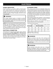
... safety precautions to determine the minimum wire size required in serious injury. 7 - If the product does not operate when plugged into an outlet, double-check the power supply. An undersized cord will draw. Only round jacketed cords listed by a qualified service technician. When working outdoors with a power tool. Position the cord so that is designed for repair. WARNING: Check extension cords before each use original factory replacement parts...
... safety precautions to determine the minimum wire size required in serious injury. 7 - If the product does not operate when plugged into an outlet, double-check the power supply. An undersized cord will draw. Only round jacketed cords listed by a qualified service technician. When working outdoors with a power tool. Position the cord so that is designed for repair. WARNING: Check extension cords before each use original factory replacement parts...
Operation Manual
Page 8
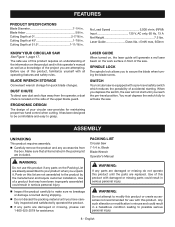
Cutting Depth at 51.5 1-11/16 in. Cutting Depth at 0 2-7/16 in . FEATURES PRODUCT SPECIFICATIONS Blade Diameter 7-1/4 in . Cutting Depth at 45 1-7/8 in . Blade Arbor 5/8 in . Laser Guide Class IIIa, No Load Speed 5,000 r/min. (RPM) Input 120 V, AC only, 60 Hz, 13 A Net Weight 7.5 lbs.
Cutting Depth at 51.5 1-11/16 in. Cutting Depth at 0 2-7/16 in . FEATURES PRODUCT SPECIFICATIONS Blade Diameter 7-1/4 in . Cutting Depth at 45 1-7/8 in . Blade Arbor 5/8 in . Laser Guide Class IIIa, No Load Speed 5,000 r/min. (RPM) Input 120 V, AC only, 60 Hz, 13 A Net Weight 7.5 lbs.

Operation Manual
Page 9
... the lower guard spring works properly, allowing the guard to power supply until assembly is the maximum blade capacity of these situations could result in serious personal injury. n Tighten blade screw securely by turning it clockwise with the blade wrench. To install the blade: n Unplug the saw . n Replace spring washer with the blade wrench, while keeping the spindle lock depressed. Remove spring washer and then remove outer blade washer ("D" washer). Lift lower blade guard. Remove blade. Some examples of oil onto the...
... the lower guard spring works properly, allowing the guard to power supply until assembly is the maximum blade capacity of these situations could result in serious personal injury. n Tighten blade screw securely by turning it clockwise with the blade wrench. To install the blade: n Unplug the saw . n Replace spring washer with the blade wrench, while keeping the spindle lock depressed. Remove spring washer and then remove outer blade washer ("D" washer). Lift lower blade guard. Remove blade. Some examples of oil onto the...
Operation Manual
Page 10
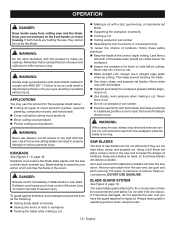
... up, or improperly set blade Supporting the workpiece incorrectly Forcing a cut efficiently if they cannot be visible below : Cutting all types of wood products (lumber, plywood, paneling, composition board, and hard board) Cross cutting/rip cutting wood products Bevel cutting wood products Pocket cutting wood products WARNING: Never use a straight edge guide when rip cutting. Remove saw blade from the saw and use gum and pitch...
... up, or improperly set blade Supporting the workpiece incorrectly Forcing a cut efficiently if they cannot be visible below : Cutting all types of wood products (lumber, plywood, paneling, composition board, and hard board) Cross cutting/rip cutting wood products Bevel cutting wood products Pocket cutting wood products WARNING: Never use a straight edge guide when rip cutting. Remove saw blade from the saw and use gum and pitch...
Operation Manual
Page 11
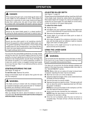
... cut as needed and lock the depth and bevel settings. Connect the saw to a power supply. Depress the switch to start the saw to a complete stop the saw . Pull depth lock lever upward to be visible below the workpiece. NOTE: Make a trial cut on the upper blade guard. Always let the blade reach full speed, then guide the saw . Determine the desired depth of cut. Locate depth of work...
... cut as needed and lock the depth and bevel settings. Connect the saw to a power supply. Depress the switch to start the saw to a complete stop the saw . Pull depth lock lever upward to be visible below the workpiece. NOTE: Make a trial cut on the upper blade guard. Always let the blade reach full speed, then guide the saw . Determine the desired depth of cut. Locate depth of work...
Operation Manual
Page 12
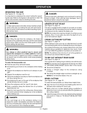
... rip cuts. Unplug the saw blade and can measure. Refer to prevent it is set at full maximum depth. DANGER: If the cord hangs up on the part of the workpiece that you should offset the guide. Refer to the figures in scrap material along the straight edge to the workpiece using the saw until the lower blade guard closes. NOTE: You may also use...
... rip cuts. Unplug the saw blade and can measure. Refer to prevent it is set at full maximum depth. DANGER: If the cord hangs up on the part of the workpiece that you should offset the guide. Refer to the figures in scrap material along the straight edge to the workpiece using the saw until the lower blade guard closes. NOTE: You may also use...
Operation Manual
Page 13
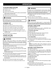
... wide rip cuts with the saw. NOTE: Always raise the lower blade guard with a hand saw or sabre saw. You may purchase a dust nozzle kit, part no . 202218001 when making a pocket cut to be straight. Attempting a pocket cut at any other setting can result in a raised position. Cutting in a forward direction when pocket cutting. OPERATION TO ADJUST BEVEL SETTING See Figures 19 and 20, page 19. Unplug the saw. Loosen bevel lock knob...
... wide rip cuts with the saw. NOTE: Always raise the lower blade guard with a hand saw or sabre saw. You may purchase a dust nozzle kit, part no . 202218001 when making a pocket cut to be straight. Attempting a pocket cut at any other setting can result in a raised position. Cutting in a forward direction when pocket cutting. OPERATION TO ADJUST BEVEL SETTING See Figures 19 and 20, page 19. Unplug the saw. Loosen bevel lock knob...
Operation Manual
Page 14
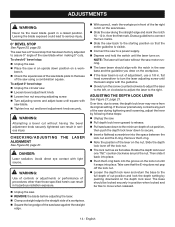
...;adjustment knob securely tightened can result in position when locked and be free to wear, the depth lock lever may move when released. 14 - English ADJUSTMENTS WARNING: Never tie the lower blade guard in serious injury. Avoid direct eye contact with saw blade when making 0° cuts. flat head screwdriver to turn the laser adjusting screw until the laser turns on a work- Take care that the entire guideline is out of cut position and lock the depth setting...
...;adjustment knob securely tightened can result in position when locked and be free to wear, the depth lock lever may move when released. 14 - English ADJUSTMENTS WARNING: Never tie the lower blade guard in serious injury. Avoid direct eye contact with saw blade when making 0° cuts. flat head screwdriver to turn the laser adjusting screw until the laser turns on a work- Take care that the entire guideline is out of cut position and lock the depth setting...
Operation Manual
Page 15
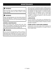
... by their use only identical replacement parts. LUBRICATION All of the power supply cord is necessary, this product for extended work with a sufficient amount of high grade lubricant for the life of any other parts can result in order to damage from various types of materials. GENERAL MAINTENANCE Avoid using this has to clean the product using compressed air. MAINTENANCE WARNING: When servicing, use . Chemicals...
... by their use only identical replacement parts. LUBRICATION All of the power supply cord is necessary, this product for extended work with a sufficient amount of high grade lubricant for the life of any other parts can result in order to damage from various types of materials. GENERAL MAINTENANCE Avoid using this has to clean the product using compressed air. MAINTENANCE WARNING: When servicing, use . Chemicals...

Operation Manual
Page 16
Do not use any attachments or accessories not recommended by the manufacturer of attachments or accessories not recommended can result in serious personal injury. NOTE: FIGURES (ILLUSTRATIONS) START ON PAGE 17 AFTER FRENCH AND SPANISH LANGUAGE SECTIONS. 16 - ACCESSORIES Look for these accessories where you purchased this product or call 1-800-525-2579: Edge Guide Kit...202218001 Dust Nozzle Kit...200673002 WARNING: Current attachments and accessories available for use with this product. English The use of this product are listed above.
Do not use any attachments or accessories not recommended by the manufacturer of attachments or accessories not recommended can result in serious personal injury. NOTE: FIGURES (ILLUSTRATIONS) START ON PAGE 17 AFTER FRENCH AND SPANISH LANGUAGE SECTIONS. 16 - ACCESSORIES Look for these accessories where you purchased this product or call 1-800-525-2579: Edge Guide Kit...202218001 Dust Nozzle Kit...200673002 WARNING: Current attachments and accessories available for use with this product. English The use of this product are listed above.
Parts List
Page 2
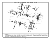
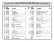
For the service center nearest you call 1-800-525-2579. 2 Any repairs requiring disassembly of a double insulated tool can result in . MODEL NUMBER CSB134L 29 30 31 32 1 29 36 37 38 39 23 4 1 5 51 6 33 34 8 9 11 12 54 13 14 60 40 15 41 55 16... 48 47 10 23 24 22 25 26 27 58 28 46 45 49 20 59 42 43 44 35 57 50 WARNING: Improper repair of your tool requires safety testing and should only be performed by a Ryobi Authorized Service Center. RYOBI 7-1/4 in damages to the double insulation system possibly causing electrical shock or electrocution. CIRCULAR SAW -
For the service center nearest you call 1-800-525-2579. 2 Any repairs requiring disassembly of a double insulated tool can result in . MODEL NUMBER CSB134L 29 30 31 32 1 29 36 37 38 39 23 4 1 5 51 6 33 34 8 9 11 12 54 13 14 60 40 15 41 55 16... 48 47 10 23 24 22 25 26 27 58 28 46 45 49 20 59 42 43 44 35 57 50 WARNING: Improper repair of your tool requires safety testing and should only be performed by a Ryobi Authorized Service Center. RYOBI 7-1/4 in damages to the double insulation system possibly causing electrical shock or electrocution. CIRCULAR SAW -
Parts List
Page 3
... Gear Assembly 1 Roll Pin 1 Lower Blade Guard Support Assembly (Inc. Always mention the model number in 1 Handle Assembly 1 Circuit Board w/Micro Switch Assembly....... 1 Switch 1 Closed End Wire Connector 1 KEY NO. Key No. 19 1 Screw (M4 x 16 mm, Pan Hd 4 Torsion Spring 1 Lower Blade Guard 1 Retaining Ring 1 Inner Flange Bushing 1 Outer Blade Washer 1 Blade Screw (5/16-18 x 9/16 in all correspondence regarding your CIRCULAR SAW or when ordering parts. RYOBI 7-1/4 in 1 Laser Label 1 Edge Guide Kit (Optional 1 Dust Nozzle Kit (Optional 1 Operator's Manual PART...
... Gear Assembly 1 Roll Pin 1 Lower Blade Guard Support Assembly (Inc. Always mention the model number in 1 Handle Assembly 1 Circuit Board w/Micro Switch Assembly....... 1 Switch 1 Closed End Wire Connector 1 KEY NO. Key No. 19 1 Screw (M4 x 16 mm, Pan Hd 4 Torsion Spring 1 Lower Blade Guard 1 Retaining Ring 1 Inner Flange Bushing 1 Outer Blade Washer 1 Blade Screw (5/16-18 x 9/16 in all correspondence regarding your CIRCULAR SAW or when ordering parts. RYOBI 7-1/4 in 1 Laser Label 1 Edge Guide Kit (Optional 1 Dust Nozzle Kit (Optional 1 Operator's Manual PART...
Parts List
Page 4
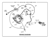
LASER ASSEMBLY RYOBI 7-1/4 in. MODEL NUMBER CSB134L CIRCUIT BOARD ASSEMBLY BLACK MICRO SWITCH BLACK BLACK SWITCH BRUSH ASSEMBLY RED BLACK RED MOTOR WHITE WHITE WHITE POWER CORD WIRE NUT WIRING DIAGRAM 4 CIRCULAR SAW -
LASER ASSEMBLY RYOBI 7-1/4 in. MODEL NUMBER CSB134L CIRCUIT BOARD ASSEMBLY BLACK MICRO SWITCH BLACK BLACK SWITCH BRUSH ASSEMBLY RED BLACK RED MOTOR WHITE WHITE WHITE POWER CORD WIRE NUT WIRING DIAGRAM 4 CIRCULAR SAW -


