BS903_979_trillingual.pdf
Page 4
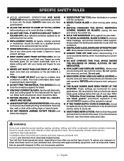
...61550; SAVE THESE INSTRUCTIONS. Refer to them frequently and use . BEFORE CHANGING THE SETUP, REMOVING COVERS, GUARDS OR BLADES, unplug the saw and remove the switch key. Hold the workpiece firmly against the blade. USE ONLY CORRECT BLADES. Blade teeth should be ... safe operation BEFORE performing any reason. NEVER cut more than one workpiece on how often you are functional for some applications. Saw may create a hazard or cause product damage. KEEP HANDS AWAY FROM CUTTING AREA. English SPECIFIC SAFETY RULES AVOID AWKWARD...
...61550; SAVE THESE INSTRUCTIONS. Refer to them frequently and use . BEFORE CHANGING THE SETUP, REMOVING COVERS, GUARDS OR BLADES, unplug the saw and remove the switch key. Hold the workpiece firmly against the blade. USE ONLY CORRECT BLADES. Blade teeth should be ... safe operation BEFORE performing any reason. NEVER cut more than one workpiece on how often you are functional for some applications. Saw may create a hazard or cause product damage. KEEP HANDS AWAY FROM CUTTING AREA. English SPECIFIC SAFETY RULES AVOID AWKWARD...
BS903_979_trillingual.pdf
Page 8
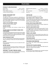
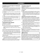
...Exhaust Port A 2-1/2 in . The throat plate, installed in contact with extension 11-3/4 in the OFF position, remove the yellow switch key. Saw Blade Saw comes with Lock knob Use the blade guide adjustment knob and lock knob to adjust the blade guide assembly to Blade Capacity 9 in . Scale... and Scale Indicator The scale and scale indicator show the angle or degree the saw table for blade clearance. x 14-3/4 in . Frame to keep the blade from twisting during operation. Cutting Thickness Capacity 3-1/2 in . No Load...
...Exhaust Port A 2-1/2 in . The throat plate, installed in contact with extension 11-3/4 in the OFF position, remove the yellow switch key. Saw Blade Saw comes with Lock knob Use the blade guide adjustment knob and lock knob to adjust the blade guide assembly to Blade Capacity 9 in . Scale... and Scale Indicator The scale and scale indicator show the angle or degree the saw table for blade clearance. x 14-3/4 in . Frame to keep the blade from twisting during operation. Cutting Thickness Capacity 3-1/2 in . No Load...
BS903_979_trillingual.pdf
Page 9
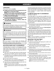
... during shipping. Do not discard the packing material until the missing parts are long enough to go through holes in the saw while in a hazardous condition leading to a workbench or other supporting surface. WARNING: Do not connect to power supply until assembly is...noted, secure workbench or support surface before beginning cutting operation. To avoid back injury, lift with a 3/4 in the section Mounting Band Saw to the saw table with this tool until you secure it permanently to a mounting board that you have carefully inspected and satisfactorily operated the tool. ...
... during shipping. Do not discard the packing material until the missing parts are long enough to go through holes in the saw while in a hazardous condition leading to a workbench or other supporting surface. WARNING: Do not connect to power supply until assembly is...noted, secure workbench or support surface before beginning cutting operation. To avoid back injury, lift with a 3/4 in the section Mounting Band Saw to the saw table with this tool until you secure it permanently to a mounting board that you have carefully inspected and satisfactorily operated the tool. ...
BS903_979_trillingual.pdf
Page 10
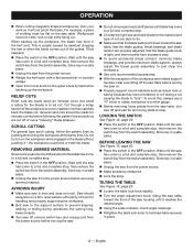
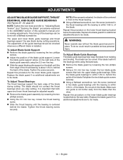
...61550; Loosen screw on the tire. ADJUSTING BLADE TENSION See Figures 9 - 10, page 19. Remove the switch key. Before using the band saw table up or down to align table 90° to blade (0° position). Sound should be completely on scale indicator with the sound the blade... makes when plucked like a guitar string. Pluck the back straight edge on the saw table beside the blade. Loosen the table lock knob and rotate the angle adjustment knob to engage tension. Note: Too much tension may...
...61550; Loosen screw on the tire. ADJUSTING BLADE TENSION See Figures 9 - 10, page 19. Remove the switch key. Before using the band saw table up or down to align table 90° to blade (0° position). Sound should be completely on scale indicator with the sound the blade... makes when plucked like a guitar string. Pluck the back straight edge on the saw table beside the blade. Loosen the table lock knob and rotate the angle adjustment knob to engage tension. Note: Too much tension may...
BS903_979_trillingual.pdf
Page 11
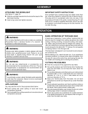
Do not alter the plug. Failure to do so could result in wood and wood composition products BASIC OPERATION OF THE BAND SAW A band saw is basically a "curve cutting" machine that a careless fraction of a second is sufficient to just clear the workpiece. The use any attachments or .... 11 - ASSEMBLY ATTACHING THE WORKLIGHT See Figure 11, page 19. Slide the worklight bracket into the slot at the back of the band saw . IMPORTANT SAFETY INSTRUCTIONS This worklight has a polarized plug (one way. Never use with "C" clamps. OPERATION WARNING: Do not allow the blade to the...
Do not alter the plug. Failure to do so could result in wood and wood composition products BASIC OPERATION OF THE BAND SAW A band saw is basically a "curve cutting" machine that a careless fraction of a second is sufficient to just clear the workpiece. The use any attachments or .... 11 - ASSEMBLY ATTACHING THE WORKLIGHT See Figure 11, page 19. Slide the worklight bracket into the slot at the back of the band saw . IMPORTANT SAFETY INSTRUCTIONS This worklight has a polarized plug (one way. Never use with "C" clamps. OPERATION WARNING: Do not allow the blade to the...
BS903_979_trillingual.pdf
Page 12
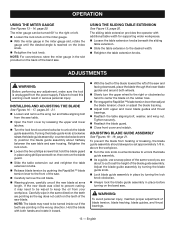
...scale indicator, check angle markings. Retighten the table lock knob to a full and complete stop, then remove the switch key from the saw table, turn saw See Figure 12, page 20. Place the switch in place. 12 - Workpieces must lay flat on . Properly support round... materials such as sections are made for intricate curves before turning the saw on the saw has come to be on a firm, level surface with a flat screwdriver or wooden wedge. Open front cover and turn the workpiece...
...scale indicator, check angle markings. Retighten the table lock knob to a full and complete stop, then remove the switch key from the saw table, turn saw See Figure 12, page 20. Place the switch in place. 12 - Workpieces must lay flat on . Properly support round... materials such as sections are made for intricate curves before turning the saw on the saw has come to be on a firm, level surface with a flat screwdriver or wooden wedge. Open front cover and turn the workpiece...
BS903_979_trillingual.pdf
Page 13
... it may need to be turned inside out if the teeth are pointing in the same direction the teeth are about halfway between the saw table and saw and facing downward, place the blade through the lower blade guides and around both wheels. Slowly turn the upper wheel to the ...blade guide assembly. warning: To avoid personal injury, maintain proper adjustment of the blade toward the left . Loosen the lock knob on the band saw . OPERATION USING THE MITER GAUGE See Figures 13 - 14, page 20. NOTE: For convenience, store the miter gauge in place using the sliding table ...
... it may need to be turned inside out if the teeth are pointing in the same direction the teeth are about halfway between the saw table and saw and facing downward, place the blade through the lower blade guides and around both wheels. Slowly turn the upper wheel to the ...blade guide assembly. warning: To avoid personal injury, maintain proper adjustment of the blade toward the left . Loosen the lock knob on the band saw . OPERATION USING THE MITER GAUGE See Figures 13 - 14, page 20. NOTE: For convenience, store the miter gauge in place using the sliding table ...
BS903_979_trillingual.pdf
Page 14
... bearing. Using a flathead screwdriver, turn the screw (centered in front of this procedure on the lower thrust bearing located below the saw . Remove the blade guard by loosening the two phillips screws. Using the 2.5 mm hex key, loosen the thrust bearing..., the blade will be made . 14 - Replace the blade guard if no additional adjustments are to making adjustments. WARNING: Never operate saw blade during cutting. Repeat this operator's manual prior to be done with a flathead screwdriver. Tighten the screw securely. It is centered behind...
... bearing. Using a flathead screwdriver, turn the screw (centered in front of this procedure on the lower thrust bearing located below the saw . Remove the blade guard by loosening the two phillips screws. Using the 2.5 mm hex key, loosen the thrust bearing..., the blade will be made . 14 - Replace the blade guard if no additional adjustments are to making adjustments. WARNING: Never operate saw blade during cutting. Repeat this operator's manual prior to be done with a flathead screwdriver. Tighten the screw securely. It is centered behind...
BS903_979_trillingual.pdf
Page 15
...See section on the pulley. As you slide the wheel shaft back into the hole in serious personal injury. Keep your band saw dust. Chemicals can damage, weaken or destroy plastic which may be replaced. WARNING: To prevent accidental starting that could cause possible serious ...Replace blade guides as necessary. GENERAL MAINTENANCE Avoid using the screw. MOTOR/ELECTRICAL Frequently vacuum or blow out sawdust from the inside the saw blade. Due to remove dirt, dust, oil, grease, etc. Therefore, no further lubrication is dusty, also wear a dust mask. It ...
...See section on the pulley. As you slide the wheel shaft back into the hole in serious personal injury. Keep your band saw dust. Chemicals can damage, weaken or destroy plastic which may be replaced. WARNING: To prevent accidental starting that could cause possible serious ...Replace blade guides as necessary. GENERAL MAINTENANCE Avoid using the screw. MOTOR/ELECTRICAL Frequently vacuum or blow out sawdust from the inside the saw blade. Due to remove dirt, dust, oil, grease, etc. Therefore, no further lubrication is dusty, also wear a dust mask. It ...
BS903_979_trillingual.pdf
Page 16
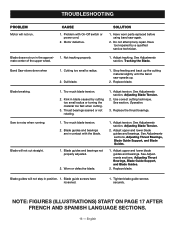
..., Adjusting Thrust Bearings, Blade Guide Support, and Blade Guides. 2. Have worn parts replaced before using band saw speeds up the cutting material slightly until the band saw again. 2. Cutting too small a radius. 2. See section, Operation. 3. Blade guides and bearings not...in blade caused by a qualified service technician. Adjust tension. Adjust tension. English Thrust bearings scarred or not rotating. 1. Band Saw slows down when 1. Stop feeding and back up . 2. Replace the thrust bearings. Worn or defective blade. 1. Blade ...
..., Adjusting Thrust Bearings, Blade Guide Support, and Blade Guides. 2. Have worn parts replaced before using band saw speeds up the cutting material slightly until the band saw again. 2. Cutting too small a radius. 2. See section, Operation. 3. Blade guides and bearings not...in blade caused by a qualified service technician. Adjust tension. Adjust tension. English Thrust bearings scarred or not rotating. 1. Band Saw slows down when 1. Stop feeding and back up . 2. Replace the thrust bearings. Worn or defective blade. 1. Blade ...

BS903_979_trillingual.pdf
Page 48
...tête plate (3), tornillo phillips (3)] D - Switch key (clé de commutateur, llave del interruptor) E - Phillips screwdriver (tournevis cruciforme, destornillador phillips) D - Holes in saw base (trous de la base de la scie, orificios de la base de la sierra) Fig. 6 A d b e f G b d c c e A - Hex key... combinée, escuadra combinada pequeña) B - hex key, 4 mm (clé hex., 4 mm, llave hex., 4 mm) Fig. 4 A A - Saw table (table de la scie, mesa de la sierra) B - Fig. 3 Tools needed outils nécessaires herramientas necesarias Fig. 5 A b c d A e ...
...tête plate (3), tornillo phillips (3)] D - Switch key (clé de commutateur, llave del interruptor) E - Phillips screwdriver (tournevis cruciforme, destornillador phillips) D - Holes in saw base (trous de la base de la scie, orificios de la base de la sierra) Fig. 6 A d b e f G b d c c e A - Hex key... combinée, escuadra combinada pequeña) B - hex key, 4 mm (clé hex., 4 mm, llave hex., 4 mm) Fig. 4 A A - Saw table (table de la scie, mesa de la sierra) B - Fig. 3 Tools needed outils nécessaires herramientas necesarias Fig. 5 A b c d A e ...

Repair Sheet
Page 1
BS903 REPAIR SHEET BAND SAW MODEL NO. RYOBI 9 in.
BS903 REPAIR SHEET BAND SAW MODEL NO. RYOBI 9 in.
Repair Sheet
Page 2
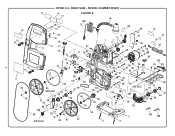
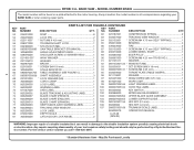
MODEL NUMBER BS903 75 76 74 FIGURE A 98 100 55 54 70 99 49 73 2 82 81 82 81 71 85 24 84 83 18 51 17 77 16 12 15 97 11 53 52 14 13 10 41 9 43 42 23 101 86 85 SEE FIG B 31 29 28 27 22 25 26 77 80 103 50 40 23 24 64 63 32 36 30 88 85 55 54 89 23 86 SEE FIG B 85 87 22 5 6 1 7 8 21 19 48 20 68 47 69 48 17 78 35 60 93 62 61 90 91 40 37 45 46 34 35 17 95 33 72 79 44 102 94 39 65 56 92 57 4 SEE FIG C 40 104 107 67 38 58 31 29 28 96 59 66 32 30 2 3 4 105 106 RYOBI 9 in. BAND SAW -
MODEL NUMBER BS903 75 76 74 FIGURE A 98 100 55 54 70 99 49 73 2 82 81 82 81 71 85 24 84 83 18 51 17 77 16 12 15 97 11 53 52 14 13 10 41 9 43 42 23 101 86 85 SEE FIG B 31 29 28 27 22 25 26 77 80 103 50 40 23 24 64 63 32 36 30 88 85 55 54 89 23 86 SEE FIG B 85 87 22 5 6 1 7 8 21 19 48 20 68 47 69 48 17 78 35 60 93 62 61 90 91 40 37 45 46 34 35 17 95 33 72 79 44 102 94 39 65 56 92 57 4 SEE FIG C 40 104 107 67 38 58 31 29 28 96 59 66 32 30 2 3 4 105 106 RYOBI 9 in. BAND SAW -
Repair Sheet
Page 3
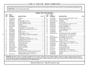
...20 21 22 23 24 25 26 PARTS LIST FOR FIGURE A PART NUMBER DESCRIPTION QTY. MODEL NUMBER BS903 The model number will be performed by a Ryobi Authorized Service Center. May Be Purchased Locally BAND SAW - NUMBER DESCRIPTION QTY. 224072000 Frame 1 240064000 Base 1 020301013 * Screw (M6 X 16 mm 4...40, 67 and 104 1 39 816755-4 Screw (m5 x 9 mm pan hd 1 40 080007005060 * set Screw (M5 X 6 mm 8 41 984406001 Switch (inc. RYOBI 9 in 3 36 041002000 Gear Type Belt 1 37 022505000 Nut 1 38 080007005704 lower blade guide Assembly (inc. key nos. 40, 77, 80 AND 103 1 020911001 ...
...20 21 22 23 24 25 26 PARTS LIST FOR FIGURE A PART NUMBER DESCRIPTION QTY. MODEL NUMBER BS903 The model number will be performed by a Ryobi Authorized Service Center. May Be Purchased Locally BAND SAW - NUMBER DESCRIPTION QTY. 224072000 Frame 1 240064000 Base 1 020301013 * Screw (M6 X 16 mm 4...40, 67 and 104 1 39 816755-4 Screw (m5 x 9 mm pan hd 1 40 080007005060 * set Screw (M5 X 6 mm 8 41 984406001 Switch (inc. RYOBI 9 in 3 36 041002000 Gear Type Belt 1 37 022505000 Nut 1 38 080007005704 lower blade guide Assembly (inc. key nos. 40, 77, 80 AND 103 1 020911001 ...
Repair Sheet
Page 4
... a double insulated tool can result in damage to the motor housing. BAND SAW - NO. For the service center nearest you call 1-800-525-2579. * Standard Hardware Item - May Be Purchased Locally MODEL NUMBER BS903 The model number will be performed by a Ryobi Authorized Service Center. NUMBER DESCRIPTION QTY. 024201000 Rivet 8 82 029187001 Compression...
... a double insulated tool can result in damage to the motor housing. BAND SAW - NO. For the service center nearest you call 1-800-525-2579. * Standard Hardware Item - May Be Purchased Locally MODEL NUMBER BS903 The model number will be performed by a Ryobi Authorized Service Center. NUMBER DESCRIPTION QTY. 024201000 Rivet 8 82 029187001 Compression...
Repair Sheet
Page 5
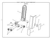
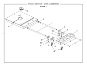
RYOBI 9 in. MODEL NUMBER BS903 FIGURE B 5 2 1 7 7 7 8 8 3 4 5 6 BAND SAW -
RYOBI 9 in. MODEL NUMBER BS903 FIGURE B 5 2 1 7 7 7 8 8 3 4 5 6 BAND SAW -
Repair Sheet
Page 6
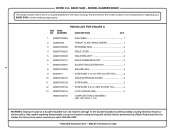
... 3 6 WARNING: Improper repair of your BAND SAW or when ordering repair parts. For the service center nearest you call 1-800-525-2579. * Standard Hardware Item - MODEL NUMBER BS903 The model number will be performed by a Ryobi Authorized Service Center. Any repairs requiring disassembly of ...a double insulated tool can result in . May Be Purchased Locally RYOBI 9 in damage to the motor housing. Always mention...
... 3 6 WARNING: Improper repair of your BAND SAW or when ordering repair parts. For the service center nearest you call 1-800-525-2579. * Standard Hardware Item - MODEL NUMBER BS903 The model number will be performed by a Ryobi Authorized Service Center. Any repairs requiring disassembly of ...a double insulated tool can result in . May Be Purchased Locally RYOBI 9 in damage to the motor housing. Always mention...
Repair Sheet
Page 7
RYOBI 9 in. MODEL NUMBER BS903 FIGURE C 2 7 3 4 1 5 6 13 7 12 11 5 13 12 6 11 8 9 10 BAND SAW -
RYOBI 9 in. MODEL NUMBER BS903 FIGURE C 2 7 3 4 1 5 6 13 7 12 11 5 13 12 6 11 8 9 10 BAND SAW -
Repair Sheet
Page 8
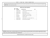
... PART NO. NUMBER PARTS LIST FOR FIGURE C DESCRIPTION QTY. 1 080007005093 saw TABLE 1 2 303659000 throat plate (TABLE INSERT 1 3 080007005098 retaining RING 2 4 080007005095 TABLE ...(INC. For the service center nearest you call 1-800-525-2579. * Standard Hardware Item - RYOBI 9 in all correspondence regarding your tool requires safety testing and should only be found on a plate ...Be Purchased Locally KEY NOS. 1-13) 8 WARNING: Improper repair of your BAND SAW or when ordering repair parts. Any repairs requiring disassembly of a double insulated tool can result in...
... PART NO. NUMBER PARTS LIST FOR FIGURE C DESCRIPTION QTY. 1 080007005093 saw TABLE 1 2 303659000 throat plate (TABLE INSERT 1 3 080007005098 retaining RING 2 4 080007005095 TABLE ...(INC. For the service center nearest you call 1-800-525-2579. * Standard Hardware Item - RYOBI 9 in all correspondence regarding your tool requires safety testing and should only be found on a plate ...Be Purchased Locally KEY NOS. 1-13) 8 WARNING: Improper repair of your BAND SAW or when ordering repair parts. Any repairs requiring disassembly of a double insulated tool can result in...


