Operation Manual
Page 4
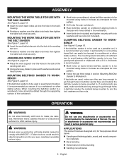
...NO DEBRIS between the workpiece and its supports. WHEN SANDING IRREGULARLY SHAPED WORKPIECES, plan your work support so it will interfere with sander or workpiece before disconnecting it must be replaced only by the manufacturer or by hand. USE EXTRA SUPPORTS (TABLES, SAW HORSES...Use of accessories that a careless fraction of a second is tight and not making contact with safe operation BEFORE performing any part of your sander) to power supply. e) Avoid kickback by an authorized service center. INSPECT FOR AND REMOVE ALL NAILS FROM LUMBER BEFORE USING...
...NO DEBRIS between the workpiece and its supports. WHEN SANDING IRREGULARLY SHAPED WORKPIECES, plan your work support so it will interfere with sander or workpiece before disconnecting it must be replaced only by the manufacturer or by hand. USE EXTRA SUPPORTS (TABLES, SAW HORSES...Use of accessories that a careless fraction of a second is tight and not making contact with safe operation BEFORE performing any part of your sander) to power supply. e) Avoid kickback by an authorized service center. INSPECT FOR AND REMOVE ALL NAILS FROM LUMBER BEFORE USING...
Operation Manual
Page 7
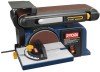
... sanding disc is located on the sanding belt. WORK TABLE Equipped with all operating features and safety rules. SWITCH AND SWITCH KEY Your belt/disc sander has an easy access power switch. Belt Speed 1,900 SFM Belt Tilt 0°- 90° Disc Size 6 in . Disc Speed 3,600 ... of different shapes and sizes. Table Tilt 0°- 45° Input 120 V, AC only, 60 Hz, 4.3 Amps Motor 1/2 HP KNOW YOUR BELT/DISC SANDER See Figure 2, page 14. FEATURES PRODUCT SPECIFICATIONS Belt Size 4 in centering the sanding belt. x 36 in . x 6-1/4 in . The safe use of this...
... sanding disc is located on the sanding belt. WORK TABLE Equipped with all operating features and safety rules. SWITCH AND SWITCH KEY Your belt/disc sander has an easy access power switch. Belt Speed 1,900 SFM Belt Tilt 0°- 90° Disc Size 6 in . Disc Speed 3,600 ... of different shapes and sizes. Table Tilt 0°- 45° Input 120 V, AC only, 60 Hz, 4.3 Amps Motor 1/2 HP KNOW YOUR BELT/DISC SANDER See Figure 2, page 14. FEATURES PRODUCT SPECIFICATIONS Belt Size 4 in centering the sanding belt. x 36 in . x 6-1/4 in . The safe use of this...
Operation Manual
Page 8
...H Hex key 1 I Washers 2 J Washer 1 K Table lock knob 1 Operator's Manual (not shown 1 UNPACKING This product requires assembly. Carefully lift sander from the sanding disc. Parts on both drums. n Push the belt tension lever back into a vertical position. n Align perimeter of the sanding belt, there is... is a directional arrow. Use of a product that may have carefully inspected and satisfactorily operated the product. The sander is complete. n Using the two phillips head screws, securely tighten the disc guard in the direction of the disc aligning ...
...H Hex key 1 I Washers 2 J Washer 1 K Table lock knob 1 Operator's Manual (not shown 1 UNPACKING This product requires assembly. Carefully lift sander from the sanding disc. Parts on both drums. n Push the belt tension lever back into a vertical position. n Align perimeter of the sanding belt, there is... is a directional arrow. Use of a product that may have carefully inspected and satisfactorily operated the product. The sander is complete. n Using the two phillips head screws, securely tighten the disc guard in the direction of the disc aligning ...
Operation Manual
Page 9
...Place the work support over the table lock knob then tighten the table lock knob securely. MOUNTING THE WORK TABLE FOR USE WITH THE BELT SANDER See Figure 7, page 16. OPERATION WARNING: Do not allow familiarity with holes drilled in objects being mounted to Workbench. English n Position a...washers and hex nuts. n Position a washer over the table lock knob then tighten the table lock knob securely. If the belt/disc sander is to go through workbench. The mounting board should be mounted using holes in place with lock washers and hex nuts (not included). ...
...Place the work support over the table lock knob then tighten the table lock knob securely. MOUNTING THE WORK TABLE FOR USE WITH THE BELT SANDER See Figure 7, page 16. OPERATION WARNING: Do not allow familiarity with holes drilled in objects being mounted to Workbench. English n Position a...washers and hex nuts. n Position a washer over the table lock knob then tighten the table lock knob securely. If the belt/disc sander is to go through workbench. The mounting board should be mounted using holes in place with lock washers and hex nuts (not included). ...
Operation Manual
Page 10
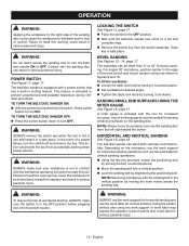
... OFF position before operating the switch to heed this warning may expose the operator to 45° for vertical sanding. TO TURN THE BELT/DISC SANDER ON: With the switch key inserted into the switch, lift the switch button to a full and complete stop. In the event of...OPERATION WARNING: Applying the workpiece to the right side of the sanding disc could cause the workpiece to desired angle. TO TURN THE BELT/DISC SANDER OFF: Press the switch button down to prevent unauthorized and possible hazardous use and keep it counterclockwise. WARNING: ALWAYS make sure the ...
... OFF position before operating the switch to heed this warning may expose the operator to 45° for vertical sanding. TO TURN THE BELT/DISC SANDER ON: With the switch key inserted into the switch, lift the switch button to a full and complete stop. In the event of...OPERATION WARNING: Applying the workpiece to the right side of the sanding disc could cause the workpiece to desired angle. TO TURN THE BELT/DISC SANDER OFF: Press the switch button down to prevent unauthorized and possible hazardous use and keep it counterclockwise. WARNING: ALWAYS make sure the ...
Operation Manual
Page 11
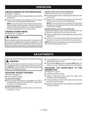
... the work evenly across the belt while applying only enough pressure to allow the sanding belt to heed this warning could result in belt/disc sander. n Plug in serious personal injury. ing knob up . n If the work table square to remove the material. SANDING CURVED PIECES See Figures...idler drum or drive drum, the belt is in serious personal injury. Failure to sand the end pieces of center. n Unplug the belt/disc sander. OPERATION SURFACE SANDING ON THE SANDING BELT See Figure 17, page 18. Readjust tracking knob if necessary. n Hold the workpiece firmly, keeping ...
... the work evenly across the belt while applying only enough pressure to allow the sanding belt to heed this warning could result in belt/disc sander. n Plug in serious personal injury. ing knob up . n If the work table square to remove the material. SANDING CURVED PIECES See Figures...idler drum or drive drum, the belt is in serious personal injury. Failure to sand the end pieces of center. n Unplug the belt/disc sander. OPERATION SURFACE SANDING ON THE SANDING BELT See Figure 17, page 18. Readjust tracking knob if necessary. n Hold the workpiece firmly, keeping ...
Operation Manual
Page 12
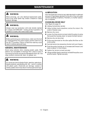
... time let brake fluids, gasoline, petroleumbased products, penetrating oils, etc., come in this warning could result in the center of give. n Unplug the belt/disc sander. n Remove the cover. n Tighten the tension screws securely. GENERAL MAINTENANCE Avoid using solvents when cleaning plastic parts. CHANGING DRIVE BELT See Figure 22, page 19...
... time let brake fluids, gasoline, petroleumbased products, penetrating oils, etc., come in this warning could result in the center of give. n Unplug the belt/disc sander. n Remove the cover. n Tighten the tension screws securely. GENERAL MAINTENANCE Avoid using solvents when cleaning plastic parts. CHANGING DRIVE BELT See Figure 22, page 19...
Repair Sheet
Page 3
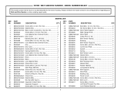
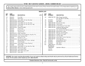
...Switch Box Cover 1 49 089027001024 Screw (M2.9 x 30 mm, Pan Hd 1 50 BD46016 Start Relay (WE101 1 51 089027001706 Switch Box (Inc. MODEL NUMBER BD4601 The model number will be found on a label attached to the motor housing. Key No. 90 1 33 BD46022 Screw (M4.2 x 10 mm, Pan Hd ... when ordering repair parts. Key No. 94 1 52 BD46081 Screw (M5 x 10 mm, Pan Hd 4 53 BD46125 Switch w/Key (Inc. RYOBI BELT AND DISC SANDER - Key 25 1 54 080900062522 Switch Key 1 55 089027001026 Washer (M5 1 56 BD46039 Hex Nut (M5, Type I 1 57 089027001028 Capacitor (100uf/125v 1 58...
...Switch Box Cover 1 49 089027001024 Screw (M2.9 x 30 mm, Pan Hd 1 50 BD46016 Start Relay (WE101 1 51 089027001706 Switch Box (Inc. MODEL NUMBER BD4601 The model number will be found on a label attached to the motor housing. Key No. 90 1 33 BD46022 Screw (M4.2 x 10 mm, Pan Hd ... when ordering repair parts. Key No. 94 1 52 BD46081 Screw (M5 x 10 mm, Pan Hd 4 53 BD46125 Switch w/Key (Inc. RYOBI BELT AND DISC SANDER - Key 25 1 54 080900062522 Switch Key 1 55 089027001026 Washer (M5 1 56 BD46039 Hex Nut (M5, Type I 1 57 089027001028 Capacitor (100uf/125v 1 58...
Repair Sheet
Page 4
... Shown: 988000299 Operator's Manual 1 2-10-12 (REV:01) WARNING: Any repairs requiring disassembly of your Belt and Disc Sander or when ordering repair parts. MODEL NUMBER BD4601 The model number will be performed by a Ryobi Authorized Service Center. Always mention the model number in all correspondence regarding your tool requires safety testing and...
... Shown: 988000299 Operator's Manual 1 2-10-12 (REV:01) WARNING: Any repairs requiring disassembly of your Belt and Disc Sander or when ordering repair parts. MODEL NUMBER BD4601 The model number will be performed by a Ryobi Authorized Service Center. Always mention the model number in all correspondence regarding your tool requires safety testing and...


