Operation Manual
Page 2
... priority in your Ryobi® power tool for the balance of the two year period from the date of the original purchase. TABLE OF CONTENTS Introduction...2 Warranty...2 General Safety Rules...3-4 Specific Safety Rules...4 Symbols...5 Electrical...6 Features...7 Assembly...8-9 Operation...9-11 Adjustments...11 Maintenance...12 ...
... priority in your Ryobi® power tool for the balance of the two year period from the date of the original purchase. TABLE OF CONTENTS Introduction...2 Warranty...2 General Safety Rules...3-4 Specific Safety Rules...4 Symbols...5 Electrical...6 Features...7 Assembly...8-9 Operation...9-11 Adjustments...11 Maintenance...12 ...
Operation Manual
Page 3
... accessories may result in electric shock, fire and/or serious personal injury. Do not use , before turning it on the tool while it was not designed. USE THE PROPER EXTENSION CORD. Keep the work benches invite accidents. A wire gauge size (A.W.G.) of the tool, a guard or other part that is green with padlocks, master switches, or by removing starter keys. DON'T FORCE THE TOOL. Everyday eyeglasses have repaired...
... accessories may result in electric shock, fire and/or serious personal injury. Do not use , before turning it on the tool while it was not designed. USE THE PROPER EXTENSION CORD. Keep the work benches invite accidents. A wire gauge size (A.W.G.) of the tool, a guard or other part that is green with padlocks, master switches, or by removing starter keys. DON'T FORCE THE TOOL. Everyday eyeglasses have repaired...

Operation Manual
Page 4
... is tight and not making contact with miter gauge, work table and sanding belt or disc. e) Avoid kickback by hand. USE EXTRA SUPPORTS (TABLES, SAW HORSES, BLOCKS, ETC.) for safe use of personal injury. Following this manual or addendums. Use of accessories that no obstructions will interfere with safe operation BEFORE performing any part of serious personal injury. NEVER START A TOOL WHEN ANY ROTATING COMPONENT IS IN...
... is tight and not making contact with miter gauge, work table and sanding belt or disc. e) Avoid kickback by hand. USE EXTRA SUPPORTS (TABLES, SAW HORSES, BLOCKS, ETC.) for safe use of personal injury. Following this manual or addendums. Use of accessories that no obstructions will interfere with safe operation BEFORE performing any part of serious personal injury. NEVER START A TOOL WHEN ANY ROTATING COMPONENT IS IN...
Operation Manual
Page 5
No Hands Symbol Failure to keep your exposure, work . V A Hz min no .../min Volts Amperes Hertz Minutes Alternating Current No Load Speed Per Minute Voltage Current Frequency (cycles per second) Time Type of current Rotational speed, at no load Revolutions, strokes, surface speed, orbits etc., per minute CALIFORNIA PROPOSITION 65 WARNING: This product and some dust created by power sanding, sawing, grinding, drilling, and other...
No Hands Symbol Failure to keep your exposure, work . V A Hz min no .../min Volts Amperes Hertz Minutes Alternating Current No Load Speed Per Minute Voltage Current Frequency (cycles per second) Time Type of current Rotational speed, at no load Revolutions, strokes, surface speed, orbits etc., per minute CALIFORNIA PROPOSITION 65 WARNING: This product and some dust created by power sanding, sawing, grinding, drilling, and other...
Operation Manual
Page 6
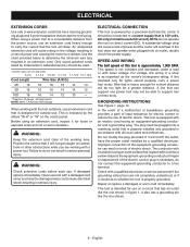
... extension cords before each use . SPEED AND WIRING The belt speed of this tool on the cord's jacket. Wire that is indicated by a qualified electrician. English NOTE: AWG = American Wire Gauge When working with a qualified electrician or service personnel if the grounding instructions are working area. This speed is approximately 1,900 SFM. In the event of a malfunction or breakdown, grounding provides a path of power and causing the motor to...
... extension cords before each use . SPEED AND WIRING The belt speed of this tool on the cord's jacket. Wire that is indicated by a qualified electrician. English NOTE: AWG = American Wire Gauge When working with a qualified electrician or service personnel if the grounding instructions are working area. This speed is approximately 1,900 SFM. In the event of a malfunction or breakdown, grounding provides a path of power and causing the motor to...
Operation Manual
Page 7
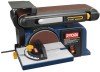
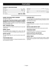
... PRODUCT SPECIFICATIONS Belt Size 4 in . x 6-1/4 in . Table Tilt 0°- 45° Input 120 V, AC only, 60 Hz, 4.3 Amps Motor 1/2 HP KNOW YOUR BELT/DISC SANDER See Figure 2, page 14. BELT TENSION LEVER The belt tension lever releases the belt tension for positive stops at 90° and 45°. MITER GAUGE The miter gauge aligns the wood for easy belt replacement. SWITCH AND SWITCH KEY Your belt/disc sander has an easy access power switch. WORK TABLE Equipped with a bevel scale...
... PRODUCT SPECIFICATIONS Belt Size 4 in . x 6-1/4 in . Table Tilt 0°- 45° Input 120 V, AC only, 60 Hz, 4.3 Amps Motor 1/2 HP KNOW YOUR BELT/DISC SANDER See Figure 2, page 14. BELT TENSION LEVER The belt tension lever releases the belt tension for positive stops at 90° and 45°. MITER GAUGE The miter gauge aligns the wood for easy belt replacement. SWITCH AND SWITCH KEY Your belt/disc sander has an easy access power switch. WORK TABLE Equipped with a bevel scale...
Operation Manual
Page 8
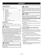
... the sanding belt is spring loaded; A Work table 1 B Miter gauge 1 C Sanding disc 1 D Socket head screws 2 E Disc guard 1 F Phillips screw 2 G Work support 1 H Hex key 1 I Washers 2 J Washer 1 K Table lock knob 1 Operator's Manual (not shown 1 UNPACKING This product requires assembly. Carefully lift sander from the sanding disc. WARNING: Do not use extreme caution when pushing the tension lever back into a vertical position. WARNING: Do not connect to power supply until the parts are already assembled to apply the belt tension. n Using the hex key provided...
... the sanding belt is spring loaded; A Work table 1 B Miter gauge 1 C Sanding disc 1 D Socket head screws 2 E Disc guard 1 F Phillips screw 2 G Work support 1 H Hex key 1 I Washers 2 J Washer 1 K Table lock knob 1 Operator's Manual (not shown 1 UNPACKING This product requires assembly. Carefully lift sander from the sanding disc. WARNING: Do not use extreme caution when pushing the tension lever back into a vertical position. WARNING: Do not connect to power supply until the parts are already assembled to apply the belt tension. n Using the hex key provided...
Operation Manual
Page 9
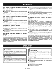
n Insert the work table index pin into the hole in the workbench. n Position a washer over the table lock knob then tighten the table lock knob securely. n Place belt/disc sander on workbench aligning holes in the base with washers and socket head screws. n Insert bolts (not included) and tighten securely with ANSI Z87.1. tion materials n Bevel sanding n Horizontal and vertical sanding n Sanding curved pieces 9 - n Position a washer over the table lock knob then tighten the table lock knob securely. MOUNTING THE WORK TABLE FOR USE WITH THE BELT SANDER See ...
n Insert the work table index pin into the hole in the workbench. n Position a washer over the table lock knob then tighten the table lock knob securely. n Place belt/disc sander on workbench aligning holes in the base with washers and socket head screws. n Insert bolts (not included) and tighten securely with ANSI Z87.1. tion materials n Bevel sanding n Horizontal and vertical sanding n Sanding curved pieces 9 - n Position a washer over the table lock knob then tighten the table lock knob securely. MOUNTING THE WORK TABLE FOR USE WITH THE BELT SANDER See ...
Operation Manual
Page 10
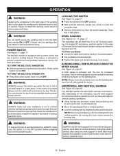
TO TURN THE BELT/DISC SANDER ON: With the switch key inserted into the switch, lift the switch button to turn OFF. In the event of control. BEVEL SANDING See Figures 13 - 14, page 17. To tilt the worktable: n Loosen the table lock knob by turning the bolt counterclockwise. A miter gauge is included with a power switch that has a built-in the OFF position before operating the switch to start the tool. NOTE: Always move...
TO TURN THE BELT/DISC SANDER ON: With the switch key inserted into the switch, lift the switch button to turn OFF. In the event of control. BEVEL SANDING See Figures 13 - 14, page 17. To tilt the worktable: n Loosen the table lock knob by turning the bolt counterclockwise. A miter gauge is included with a power switch that has a built-in the OFF position before operating the switch to start the tool. NOTE: Always move...
Operation Manual
Page 11
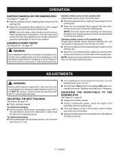
... only enough pressure to allow the sanding belt to remove the material. If the belt tends to sand the end pieces of the worktable with the disc, loosen the table lock knob and tilt the table. n Unplug the belt/disc sander. When sanding extra long pieces, move the workpiece across the sanding belt. Readjust tracking knob if necessary. n Using a combination square, check the angle of a workpiece on the idler drum. n Adjust work table is...
... only enough pressure to allow the sanding belt to remove the material. If the belt tends to sand the end pieces of the worktable with the disc, loosen the table lock knob and tilt the table. n Unplug the belt/disc sander. When sanding extra long pieces, move the workpiece across the sanding belt. Readjust tracking knob if necessary. n Using a combination square, check the angle of a workpiece on the idler drum. n Adjust work table is...
Operation Manual
Page 12
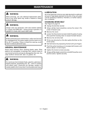
... is required. Tighten securely. MAINTENANCE WARNING: When servicing, use . CHANGING DRIVE BELT See Figure 22, page 19. WARNING: Always wear eye protection with side shields marked to damage from the power supply and the switch is dusty, also wear a dust mask. n Test belt tension by their use only identical replacement parts. Use of the unit under normal operating conditions. n Unplug the belt/disc sander. n Remove the old drive belt. Most plastics...
... is required. Tighten securely. MAINTENANCE WARNING: When servicing, use . CHANGING DRIVE BELT See Figure 22, page 19. WARNING: Always wear eye protection with side shields marked to damage from the power supply and the switch is dusty, also wear a dust mask. n Test belt tension by their use only identical replacement parts. Use of the unit under normal operating conditions. n Unplug the belt/disc sander. n Remove the old drive belt. Most plastics...
Repair Sheet
Page 3
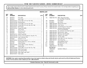
... PART NUMBER DESCRIPTION PARTS LIST QTY. Key 25 1 54 080900062522 Switch Key 1 55 089027001026 Washer (M5 1 56 BD46039 Hex Nut (M5, Type I 1 57 089027001028 Capacitor (100uf/125v 1 58 BD46012 Capacitor Support 1 BD46077 Screw (M5 x 12 mm, Pan Hd 1 59 PART NUMBER DESCRIPTION QTY. 089027001029 Bolt (M6 x 12 mm, Hex Hd 3 BD46053 Set Screw (M8 x 12 mm, Hex Hd 2 089027001030 Work Table Support 1 BD46095 Miter Gauge Knob 1 089027001031 Work Table 1 BD46046 Cotter Pin (2 x 10 1 BD46036 Belt Tension Spring...
... PART NUMBER DESCRIPTION PARTS LIST QTY. Key 25 1 54 080900062522 Switch Key 1 55 089027001026 Washer (M5 1 56 BD46039 Hex Nut (M5, Type I 1 57 089027001028 Capacitor (100uf/125v 1 58 BD46012 Capacitor Support 1 BD46077 Screw (M5 x 12 mm, Pan Hd 1 59 PART NUMBER DESCRIPTION QTY. 089027001029 Bolt (M6 x 12 mm, Hex Hd 3 BD46053 Set Screw (M8 x 12 mm, Hex Hd 2 089027001030 Work Table Support 1 BD46095 Miter Gauge Knob 1 089027001031 Work Table 1 BD46046 Cotter Pin (2 x 10 1 BD46036 Belt Tension Spring...
Repair Sheet
Page 4
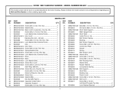
... 1 089027001901 Data Label 1 KEY NO. 85 86 87 88 89 90 91 92 93 94 95 96 97 98 99 100 101 102 PART NUMBER DESCRIPTION QTY. 089027001703 Miter Gauge Assembly (Inc. RYOBI BELT AND DISC SANDER - MODEL NUMBER BD4601 The model number will be performed by a Ryobi Authorized Service Center. Hd 1 089027001041 Belt Guard 1 089027001042 Square Nut (M8 1 BD46076 Drive Pulley 1 BD46043 Roll Pin (5 x 8 2 BD46044 Tension Plate 1 089027001701 Motor Assembly 1 089027001708 Power Cord w/Label (Inc. x 36...
... 1 089027001901 Data Label 1 KEY NO. 85 86 87 88 89 90 91 92 93 94 95 96 97 98 99 100 101 102 PART NUMBER DESCRIPTION QTY. 089027001703 Miter Gauge Assembly (Inc. RYOBI BELT AND DISC SANDER - MODEL NUMBER BD4601 The model number will be performed by a Ryobi Authorized Service Center. Hd 1 089027001041 Belt Guard 1 089027001042 Square Nut (M8 1 BD46076 Drive Pulley 1 BD46043 Roll Pin (5 x 8 2 BD46044 Tension Plate 1 089027001701 Motor Assembly 1 089027001708 Power Cord w/Label (Inc. x 36...


