Repair Sheet
Page 3
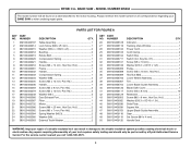
... 089120406083 DESCRIPTION QTY. Hd 2 Washer (ID6.3 x OD16 x 1.5t 1 Slide Plate 1 Square Nut 1 Upper Blade Guide Assembly 1 Gear 1 Set Screw (M4 x 4 mm 1 Handle Seat 1 WARNING: Improper repair of your BAND SAW or when ordering repair parts. Indicator 1 Tracking View Window 1 Power Cord 1 Cord Clamp 2 Switch Box 1 Switch (Inc. Hd 2 Frame 1 Handle 1 Compression Spring 1 Washer (M8 4 Screw (M5 x 12 mm, Pan Hd 2 Handle 1 Screw (M5 x 8 mm, Pan Hd 2 Screw (M5 x 10 mm, Pan Hd 5 Washer (M5 5 Dust Exhaust Port 1 Filter 1 Motor 1 Screw (M8 × 20...
... 089120406083 DESCRIPTION QTY. Hd 2 Washer (ID6.3 x OD16 x 1.5t 1 Slide Plate 1 Square Nut 1 Upper Blade Guide Assembly 1 Gear 1 Set Screw (M4 x 4 mm 1 Handle Seat 1 WARNING: Improper repair of your BAND SAW or when ordering repair parts. Indicator 1 Tracking View Window 1 Power Cord 1 Cord Clamp 2 Switch Box 1 Switch (Inc. Hd 2 Frame 1 Handle 1 Compression Spring 1 Washer (M8 4 Screw (M5 x 12 mm, Pan Hd 2 Handle 1 Screw (M5 x 8 mm, Pan Hd 2 Screw (M5 x 10 mm, Pan Hd 5 Washer (M5 5 Dust Exhaust Port 1 Filter 1 Motor 1 Screw (M8 × 20...
Repair Sheet
Page 4
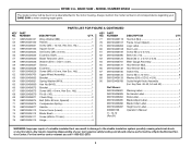
... 1 No Hands Label 1 Data Label 1 Blade Adjust Label 1 Blade Order Label 1 Height Lock Label 1 Operator's Manual WARNING: Improper repair of your BAND SAW or when ordering repair parts. RYOBI 9 in . Hex Nut (M4 8组 Frame Cover (Upper 1 Logo Label 1 Door Lock 2 Screw (M4.2 x 6 mm 1 Belt (130 x 10 1 Blade (62 in . x 6 mm x 0.3t 1 Miter Gauge Assembly 1 Hex Wrench (M2 1 Hex Wrench (M4 1 Switch Key 1 Screw (M4 x 10 mm 8 Washer (ID6 x OD12 x 0.5t 1 Guide Height Knob Assembly (Inc. For the service center...
... 1 No Hands Label 1 Data Label 1 Blade Adjust Label 1 Blade Order Label 1 Height Lock Label 1 Operator's Manual WARNING: Improper repair of your BAND SAW or when ordering repair parts. RYOBI 9 in . Hex Nut (M4 8组 Frame Cover (Upper 1 Logo Label 1 Door Lock 2 Screw (M4.2 x 6 mm 1 Belt (130 x 10 1 Blade (62 in . x 6 mm x 0.3t 1 Miter Gauge Assembly 1 Hex Wrench (M2 1 Hex Wrench (M4 1 Switch Key 1 Screw (M4 x 10 mm 8 Washer (ID6 x OD12 x 0.5t 1 Guide Height Knob Assembly (Inc. For the service center...

Repair Sheet
Page 8
... Blade Wheel (Lower 1 10 089120406098 Spring Washer (M5 3 11 089120406097 Screw (M5 x 16 mm 3 WARNING: Improper repair of your BAND SAW or when ordering repair parts. Any repairs requiring disassembly of a double insulated tool can result in damage to the motor housing. PARTS LIST FOR FIGURE C KEY PART NO. For the service center nearest you call 1-800-525-2579. 8 MODEL NUMBER BS904 The model number will be performed by a Ryobi Authorized Service Center...
... Blade Wheel (Lower 1 10 089120406098 Spring Washer (M5 3 11 089120406097 Screw (M5 x 16 mm 3 WARNING: Improper repair of your BAND SAW or when ordering repair parts. Any repairs requiring disassembly of a double insulated tool can result in damage to the motor housing. PARTS LIST FOR FIGURE C KEY PART NO. For the service center nearest you call 1-800-525-2579. 8 MODEL NUMBER BS904 The model number will be performed by a Ryobi Authorized Service Center...

User Manual
Page 2
... RYOBI® power tools with the original product. ADDITIONAL LIMITATIONS: Any implied warranties granted under normal usage and does not cover any case, within ninety (90) days or less. TABLE OF CONTENTS Introduction...2 Warranty...2 General Safety Rules...3-4 Specific Safety Rules...4-5 Symbols...6 Electrical...7 Features...8 Assembly...9-11 Operation...11-13 Adjustments...13-14 Maintenance...15 Troubleshooting...
... RYOBI® power tools with the original product. ADDITIONAL LIMITATIONS: Any implied warranties granted under normal usage and does not cover any case, within ninety (90) days or less. TABLE OF CONTENTS Introduction...2 Warranty...2 General Safety Rules...3-4 Specific Safety Rules...4-5 Symbols...6 Electrical...7 Features...8 Assembly...9-11 Operation...11-13 Adjustments...13-14 Maintenance...15 Troubleshooting...

User Manual
Page 3
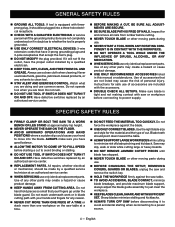
... will draw. Be sure switch is safer than using your hand and frees both hands to a complete stop. DO NOT ABUSE CORD. TURN THE POWER OFF. Wear a face or dust mask if the cutting operation is the equipment-grounding conductor. A wire gauge size (A.W.G.) of wood on . KEEP WORK AREA CLEAN. Use clamps or a vise to follow all instructions. It's is off . NEVER USE IN AN EXPLOSIVE ATMOSPHERE...
... will draw. Be sure switch is safer than using your hand and frees both hands to a complete stop. DO NOT ABUSE CORD. TURN THE POWER OFF. Wear a face or dust mask if the cutting operation is the equipment-grounding conductor. A wire gauge size (A.W.G.) of wood on . KEEP WORK AREA CLEAN. Use clamps or a vise to follow all instructions. It's is off . NEVER USE IN AN EXPLOSIVE ATMOSPHERE...
User Manual
Page 4
...; NEVER cut . All repairs, whether electrical or mechanical, should point down toward the table. Always SUPPORT LARGE WORKPIECES while cutting to clean tool. STAY ALERT AND EXERCISE CONTROL. Inspect for any other moving parts during use . BEFORE CHANGING THE SETUP, REMOVING COVERS, GUARDS OR BLADES, unplug the saw table. To avoid accidental blade contact, minimize blade breakage, and provide maximum blade support, always adjust the blade guide assembly to power supply...
...; NEVER cut . All repairs, whether electrical or mechanical, should point down toward the table. Always SUPPORT LARGE WORKPIECES while cutting to clean tool. STAY ALERT AND EXERCISE CONTROL. Inspect for any other moving parts during use . BEFORE CHANGING THE SETUP, REMOVING COVERS, GUARDS OR BLADES, unplug the saw table. To avoid accidental blade contact, minimize blade breakage, and provide maximum blade support, always adjust the blade guide assembly to power supply...
User Manual
Page 5
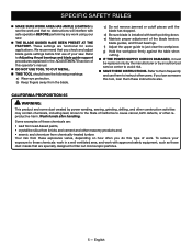
... from the blade. SPECIFIC SAFETY RULES MAKE SURE WORK AREA HAS AMPLE LIGHTING to see the work and that are functional for some dust created by an authorized service center to avoid risk. SAVE THESE INSTRUCTIONS. Refer to Adjusting thrust bearings and blade guide support procedures explained in a well ventilated area, and work . Wash hands after handling. These settings are specially designed to cut metal. ...
... from the blade. SPECIFIC SAFETY RULES MAKE SURE WORK AREA HAS AMPLE LIGHTING to see the work and that are functional for some dust created by an authorized service center to avoid risk. SAVE THESE INSTRUCTIONS. Refer to Adjusting thrust bearings and blade guide support procedures explained in a well ventilated area, and work . Wash hands after handling. These settings are specially designed to cut metal. ...

User Manual
Page 7
... the grounding plug can support one power tool may not be connected to reduce the risk of electric shock. WARNING: Check extension cords before each use . Do not operate this product. 7 - For voltage, the wiring in a risk of electric shock. A line that can result in a shop is designed for lights cannot properly carry a power tool motor. Only round jacketed cords listed by Underwriter's Laboratories (UL...
... the grounding plug can support one power tool may not be connected to reduce the risk of electric shock. WARNING: Check extension cords before each use . Do not operate this product. 7 - For voltage, the wiring in a risk of electric shock. A line that can result in a shop is designed for lights cannot properly carry a power tool motor. Only round jacketed cords listed by Underwriter's Laboratories (UL...

User Manual
Page 8
... switch key. Blade Guard Protects the operator from coming in place before turning on the wheels. Latch Easy open latches allow front cover to -read indicator shows the exact angle for various sawing applications. To lock in . Miter Gauge This gauge aligns the wood for bevel cutting. Tightening the table lock lever locks the saw table to Blade Capacity 9 in place. Frame to be opened for making adjustments for a miter cut at different angles. The safe use the tool...
... switch key. Blade Guard Protects the operator from coming in place before turning on the wheels. Latch Easy open latches allow front cover to -read indicator shows the exact angle for various sawing applications. To lock in . Miter Gauge This gauge aligns the wood for bevel cutting. Tightening the table lock lever locks the saw table to Blade Capacity 9 in place. Frame to be opened for making adjustments for a miter cut at different angles. The safe use the tool...
User Manual
Page 9
... or damage occurred during use this saw base, lock washers, hex nuts, and the thickness of the bench. Note: It may have been improperly assembled could result in accidental starting and possible serious personal injury. A Saw Table 1 B Miter Gauge 1 C Hex key, 2 mm 1 D Hex key, 4 mm 1 E Washer 1 F Table Lock Lever 1 Operator's Manual (not shown 1 UNPACKING This product requires assembly. Carefully lift the saw base with this purpose. WARNING: Do not use . Use of a product that...
... or damage occurred during use this saw base, lock washers, hex nuts, and the thickness of the bench. Note: It may have been improperly assembled could result in accidental starting and possible serious personal injury. A Saw Table 1 B Miter Gauge 1 C Hex key, 2 mm 1 D Hex key, 4 mm 1 E Washer 1 F Table Lock Lever 1 Operator's Manual (not shown 1 UNPACKING This product requires assembly. Carefully lift the saw base with this purpose. WARNING: Do not use . Use of a product that...

User Manual
Page 10
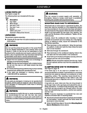
.... ASSEMBLY MOUNTING THE SAW TABLE See Figures 6 - 7, pages 18 - 19. Remove the D-nut, washers, and wing screw on the saw table. Standing at anytime. Pluck the back straight edge of the saw blade like a guitar string while turning the tension knob. Tighten the saw table to completely compress the spring. NOTE: The wing screw goes below the saw table to break. Retighten the table lock lever. Using an adjustable wrench, loosen the jam nut. Turn...
.... ASSEMBLY MOUNTING THE SAW TABLE See Figures 6 - 7, pages 18 - 19. Remove the D-nut, washers, and wing screw on the saw table. Standing at anytime. Pluck the back straight edge of the saw blade like a guitar string while turning the tension knob. Tighten the saw table to completely compress the spring. NOTE: The wing screw goes below the saw table to break. Retighten the table lock lever. Using an adjustable wrench, loosen the jam nut. Turn...
User Manual
Page 11
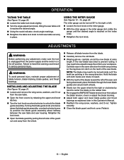
... hands when feeding the work ; When using the band saw . Turn the saw off, remove the switch key, and unplug the saw without the blade guard secured and the front covers locked. Do not force the work into your fingers will go under the blade guard. Avoid awkward operations and hand positions where a sudden slip could result in .; English These settings are functional for straight-line cutting operations like cross cutting, mitering, beveling, compound cutting...
... hands when feeding the work ; When using the band saw . Turn the saw off, remove the switch key, and unplug the saw without the blade guard secured and the front covers locked. Do not force the work into your fingers will go under the blade guard. Avoid awkward operations and hand positions where a sudden slip could result in .; English These settings are functional for straight-line cutting operations like cross cutting, mitering, beveling, compound cutting...
User Manual
Page 12
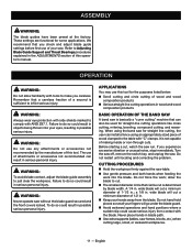
OPERATION Never use a "V" block or clamp workpiece to a miter gauge. Before removing loose pieces from the saw table, turn saw off and wait for all moving the saw. Do not remove jammed cutoff pieces until blade has come to a full and complete stop. Choose the right size and style blade for the material and type of cut you plan to do. Make sure that the blade teeth...
OPERATION Never use a "V" block or clamp workpiece to a miter gauge. Before removing loose pieces from the saw table, turn saw off and wait for all moving the saw. Do not remove jammed cutoff pieces until blade has come to a full and complete stop. Choose the right size and style blade for the material and type of cut you plan to do. Make sure that the blade teeth...
User Manual
Page 13
... screw, washers, and D-nut from the saw table. Open the front covers by pulling the left of the guard out and away from the wheel. Release all blade tension from your workpiece. Tighten securely. Close the blade guard and front cover. Failure to hold saw table securely in place. Turning the blade guide knob (clockwise raises the blade guide assembly; check or adjust the blade tracking. Adjust both wheels. Slowly turn...
... screw, washers, and D-nut from the saw table. Open the front covers by pulling the left of the guard out and away from the wheel. Release all blade tension from your workpiece. Tighten securely. Close the blade guard and front cover. Failure to hold saw table securely in place. Turning the blade guide knob (clockwise raises the blade guide assembly; check or adjust the blade tracking. Adjust both wheels. Slowly turn...

User Manual
Page 14
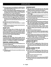
... turning on the shaft until the front edge of the blade during cutting operations. The blade should not contact the thrust bearings when you are about the thickness of the blade guide assembly. Tighten the screw securely. Push the right guide to allow 1/64 in . Slowly rotate wheel one full rotation. clearance between the blade and guide (about to cut to set screws using hex keys. Slide the upper blade guide support...
... turning on the shaft until the front edge of the blade during cutting operations. The blade should not contact the thrust bearings when you are about the thickness of the blade guide assembly. Tighten the screw securely. Push the right guide to allow 1/64 in . Slowly rotate wheel one full rotation. clearance between the blade and guide (about to cut to set screws using hex keys. Slide the upper blade guide support...

User Manual
Page 15
... automobile type wax to be adjusted or replaced. Remove the screw and washer then pull the brush off position. TIRES Cleaning tires: Pitch and sawdust accumulates on Installing and Adjusting the Blade, page 13. Pry the worn tire away from the motor. Replacing tires: Open front cover and remove saw dust. MOTOR/ELECTRICAL Frequently vacuum or blow out sawdust from the wheel carefully...
... automobile type wax to be adjusted or replaced. Remove the screw and washer then pull the brush off position. TIRES Cleaning tires: Pitch and sawdust accumulates on Installing and Adjusting the Blade, page 13. Pry the worn tire away from the motor. Replacing tires: Open front cover and remove saw dust. MOTOR/ELECTRICAL Frequently vacuum or blow out sawdust from the wheel carefully...
User Manual
Page 16
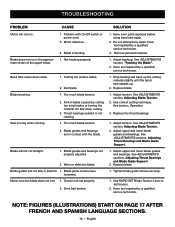
... service technician. Cutting too small a radius. 2. Blade guides and bearings not properly adjusted. 2. Use RAPID SET Blade Tension Lever to set properly. 1. NOTE: Figures (illustrations) start on page 17 after French and Spanish language sections. 16 - Adjust upper and lower blade guides and bearings. Blade guide screws have loosened. 1. Remove jammed material. Adjust tracking, See Adjustments section, "Tracking the Blade". 2. Replace blade. Tighten blade guide screws securely. Have tool repaired by cutting too small radius or turning...
... service technician. Cutting too small a radius. 2. Blade guides and bearings not properly adjusted. 2. Use RAPID SET Blade Tension Lever to set properly. 1. NOTE: Figures (illustrations) start on page 17 after French and Spanish language sections. 16 - Adjust upper and lower blade guides and bearings. Blade guide screws have loosened. 1. Remove jammed material. Adjust tracking, See Adjustments section, "Tracking the Blade". 2. Replace blade. Tighten blade guide screws securely. Have tool repaired by cutting too small radius or turning...
User Manual 3
Page 3
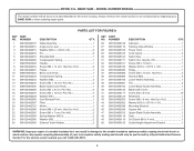
... 2 Blade Guard Lock Knob 1 Screw (M5 x 8 mm, Pan Hd 2 Screw (M5 x 10 mm, Pan Hd 5 Washer (M5 5 Dust Exhaust Port 1 Filter 1 Motor 1 Screw (M8 × 20 mm, Hex Soc. Hd 2 Washer (ID6.3 x OD16 x 1.5t 1 Mounting Bracket 1 Square Nut 1 Upper Blade Guide Assembly 1 Gear 1 Set Screw (M4 x 4 mm 1 Guide Height Adjustment Bracket 1 WARNING: Improper repair of your BAND SAW or when ordering repair parts. RYOBI 9 in damage to the motor housing. MODEL NUMBER BS904G The model number will be performed by a Ryobi Authorized Service Center. PARTS LIST...
... 2 Blade Guard Lock Knob 1 Screw (M5 x 8 mm, Pan Hd 2 Screw (M5 x 10 mm, Pan Hd 5 Washer (M5 5 Dust Exhaust Port 1 Filter 1 Motor 1 Screw (M8 × 20 mm, Hex Soc. Hd 2 Washer (ID6.3 x OD16 x 1.5t 1 Mounting Bracket 1 Square Nut 1 Upper Blade Guide Assembly 1 Gear 1 Set Screw (M4 x 4 mm 1 Guide Height Adjustment Bracket 1 WARNING: Improper repair of your BAND SAW or when ordering repair parts. RYOBI 9 in damage to the motor housing. MODEL NUMBER BS904G The model number will be performed by a Ryobi Authorized Service Center. PARTS LIST...

User Manual 3
Page 4
... Lever Mount 1 Eccentric 1 Screw (M6 x 16 mm, Hex Soc. Key Nos. 48-52, 54 and 59 1 Warning Label 1 No Hands Label 1 Data Label 1 Blade Adjust Label 1 Blade Order Label 1 Height Lock Label 1 Operator's Manual WARNING: Improper repair of your BAND SAW or when ordering repair parts. For the service center nearest you call 1-800-525-2579. 4 MODEL NUMBER BS904G The model number will be performed by a Ryobi Authorized Service Center. Wavy Washer (M6 1 Blade Guard Adjust Knob 1 Screw...
... Lever Mount 1 Eccentric 1 Screw (M6 x 16 mm, Hex Soc. Key Nos. 48-52, 54 and 59 1 Warning Label 1 No Hands Label 1 Data Label 1 Blade Adjust Label 1 Blade Order Label 1 Height Lock Label 1 Operator's Manual WARNING: Improper repair of your BAND SAW or when ordering repair parts. For the service center nearest you call 1-800-525-2579. 4 MODEL NUMBER BS904G The model number will be performed by a Ryobi Authorized Service Center. Wavy Washer (M6 1 Blade Guard Adjust Knob 1 Screw...
User Manual 3
Page 8
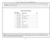
... the model number in . NUMBER DESCRIPTION QTY. 1 089120406063 Shaft 1 2 089120406064 Ball Bearing (6000-2RZ 4 3 089120406065 Retaining Ring 4 4 089120406066 Blade Wheel (Upper 1 5 089120406067 Tire 2 6 089120406069 Retaining Ring 2 7 089120406090 Shaft 1 8 089120406091 Pulley 1 9 089120406093 Blade Wheel (Lower 1 10 089120406098 Spring Washer (M5 3 11 089120406097 Screw (M5 x 16 mm 3 WARNING: Improper repair of your BAND SAW or when ordering repair parts. RYOBI 9 in all correspondence regarding your tool requires safety testing...
... the model number in . NUMBER DESCRIPTION QTY. 1 089120406063 Shaft 1 2 089120406064 Ball Bearing (6000-2RZ 4 3 089120406065 Retaining Ring 4 4 089120406066 Blade Wheel (Upper 1 5 089120406067 Tire 2 6 089120406069 Retaining Ring 2 7 089120406090 Shaft 1 8 089120406091 Pulley 1 9 089120406093 Blade Wheel (Lower 1 10 089120406098 Spring Washer (M5 3 11 089120406097 Screw (M5 x 16 mm 3 WARNING: Improper repair of your BAND SAW or when ordering repair parts. RYOBI 9 in all correspondence regarding your tool requires safety testing...


