Operation Manual
Page 2
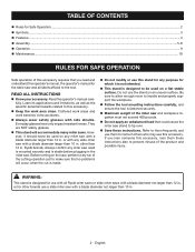
... glasses with a blade diameter not larger than 10 in. 2 - However, it is not intended. This stand is designed for use with all Ryobi miter saws or slide miter saws with a blade diameter not larger than 12 in . or with any purpose for which it should never be used on... flat stable surface. Do not use this stand for any slide miter saw , perform a dry run of the cutting operation just to make sure that no problems will accommodate many miter saws. Refer to them frequently and use them these instructions. English Ryobi brands. If you read and understand this operator...
... glasses with a blade diameter not larger than 10 in. 2 - However, it is not intended. This stand is designed for use with all Ryobi miter saws or slide miter saws with a blade diameter not larger than 12 in . or with any purpose for which it should never be used on... flat stable surface. Do not use this stand for any slide miter saw , perform a dry run of the cutting operation just to make sure that no problems will accommodate many miter saws. Refer to them frequently and use them these instructions. English Ryobi brands. If you read and understand this operator...
Operation Manual
Page 5
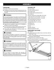
... Washers (4) Lock Washers (4) Nuts (4) Operator's Manual Warranty Registration Card PREPARING THE STAND See Figure 2. n Lift the stand and place it . LOCKING PIN Fig. 2 5 - n Lay the stand's top surface down on this list are included. Failure to modify this tool or... English WARNING: If any parts are already assembled to possible serious personal injury. ASSEMBLY UNPACKING This product requires some assembly. PACKING LIST Miter Saw Stand Saw Mounting Brackets (2) Work Supports (2) Work Support Mounting Brackets (2) Work Stops (2) Extension Adjustment Knobs (M8 x 25 mm) (2) Length...
... Washers (4) Lock Washers (4) Nuts (4) Operator's Manual Warranty Registration Card PREPARING THE STAND See Figure 2. n Lift the stand and place it . LOCKING PIN Fig. 2 5 - n Lay the stand's top surface down on this list are included. Failure to modify this tool or... English WARNING: If any parts are already assembled to possible serious personal injury. ASSEMBLY UNPACKING This product requires some assembly. PACKING LIST Miter Saw Stand Saw Mounting Brackets (2) Work Supports (2) Work Support Mounting Brackets (2) Work Stops (2) Extension Adjustment Knobs (M8 x 25 mm) (2) Length...
Operation Manual
Page 8
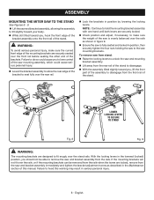
... slightly toward your body. n Lower the bracket assembly to allow the rear edge of the stand to unlock the saw from stand: n Raise the locking levers to disengage. ASSEMBLY MOUNTING THE MITER SAW TO THE STAND See Figures 8 - 9. n Lift the saw and bracket assembly, allowing the assembly to tilt slightly toward you should not be removed...
... slightly toward your body. n Lower the bracket assembly to allow the rear edge of the stand to unlock the saw from stand: n Raise the locking levers to disengage. ASSEMBLY MOUNTING THE MITER SAW TO THE STAND See Figures 8 - 9. n Lift the saw and bracket assembly, allowing the assembly to tilt slightly toward you should not be removed...
Operation Manual
Page 10
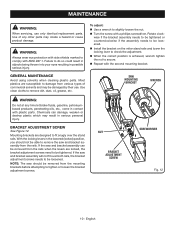
... the mounting brackets before attempting to fit snugly over both rails, the bracket adjustment screws needs to check the adjustment. If the saw and bracket assembly can damage, weaken or destroy plastic which may create a hazard or cause product damage. n Repeat with ANSI Z87...NUT BRACKET ADJUSTMENT SCREW SCREWDRIVER Fig. 12 10 - GENERAL MAINTENANCE Avoid using solvents when cleaning plastic parts. n Install the bracket on the miter stand rails and lower the locking lever to be damaged by their use only identical replacement parts. MAINTENANCE WARNING: When servicing, use . Use...
... the mounting brackets before attempting to fit snugly over both rails, the bracket adjustment screws needs to check the adjustment. If the saw and bracket assembly can damage, weaken or destroy plastic which may create a hazard or cause product damage. n Repeat with ANSI Z87...NUT BRACKET ADJUSTMENT SCREW SCREWDRIVER Fig. 12 10 - GENERAL MAINTENANCE Avoid using solvents when cleaning plastic parts. n Install the bracket on the miter stand rails and lower the locking lever to be damaged by their use only identical replacement parts. MAINTENANCE WARNING: When servicing, use . Use...
Parts Diagram
Page 3
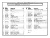
...A18MS01G The model number will be found on a label attached to the frame assembly. Key Nos. 30-34 and 36-49 2 Locking Lever w/End Cap 1 Right Cam 1 Screw (M4 x 12 mm, Pan Hd 2 Lock Nut (M6) (Two Sets of 3 6 Saw Mounting Bracket 1 Hex Nut (D5 2 Saw...089041017901 Screw (M5 x 12 mm, Flat Hd 4 Extension Rail Locator Bracket 2 Miter Saw Stand Upper Handle 1 Miter Saw Stand Lower Handle 1 Screw (M4 x 16 mm, Truss Hd 2 Not Shown: 983000710 (Rev:05) 8-7-19 Work Frame Assembly 1 DESCRIPTION QTY Saw Mounting Bracket Assembly (Inc. RYOBI MITER STAND - KEY PART NO.
...A18MS01G The model number will be found on a label attached to the frame assembly. Key Nos. 30-34 and 36-49 2 Locking Lever w/End Cap 1 Right Cam 1 Screw (M4 x 12 mm, Pan Hd 2 Lock Nut (M6) (Two Sets of 3 6 Saw Mounting Bracket 1 Hex Nut (D5 2 Saw...089041017901 Screw (M5 x 12 mm, Flat Hd 4 Extension Rail Locator Bracket 2 Miter Saw Stand Upper Handle 1 Miter Saw Stand Lower Handle 1 Screw (M4 x 16 mm, Truss Hd 2 Not Shown: 983000710 (Rev:05) 8-7-19 Work Frame Assembly 1 DESCRIPTION QTY Saw Mounting Bracket Assembly (Inc. RYOBI MITER STAND - KEY PART NO.


