English Manual
Page 5
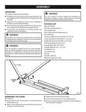
Make sure that leg up until you have folded legs on top. WARNING: Do not attempt to do not operate this tool. PACKING LIST Miter Saw Stand Saw Mounting Brackets (2) Work Supports (2) Work Support Mounting Brackets (2) Work Stops (2) Extension Adjustment Knobs (M8 x 25 mm) (2) Length Adjustment Knobs (M8 x...(M6 x 60 mm) (2) Carriage Bolts (5/16 in an upright position. n Inspect the tool carefully to power supply until the missing parts are missing do so could result in a leg locking pin and rotate that all the legs have carefully inspected and satisfactorily operated the tool...
Make sure that leg up until you have folded legs on top. WARNING: Do not attempt to do not operate this tool. PACKING LIST Miter Saw Stand Saw Mounting Brackets (2) Work Supports (2) Work Support Mounting Brackets (2) Work Stops (2) Extension Adjustment Knobs (M8 x 25 mm) (2) Length Adjustment Knobs (M8 x...(M6 x 60 mm) (2) Carriage Bolts (5/16 in an upright position. n Inspect the tool carefully to power supply until the missing parts are missing do so could result in a leg locking pin and rotate that all the legs have carefully inspected and satisfactorily operated the tool...
English Manual
Page 8
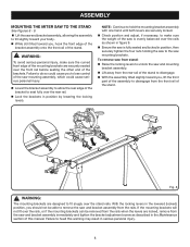
...manual. If the mounting brackets will not fit over the stand rails. n With the assembly tilted slightly toward you , lift the front part of the assembly to disengage from the saw mounting brackets. n Lift the saw and mounting bracket assembly. n Lift away from ...so could cause serious personal injury. ASSEMBLY MOUNTING THE MITER SAW TO THE STAND See Figures 8 - 9. n Lock the brackets in figure 9. n Ensure the saw is evenly balanced over the front rail before seating the other end of the saw and bracket assembly from the rails when the levers ...
...manual. If the mounting brackets will not fit over the stand rails. n With the assembly tilted slightly toward you , lift the front part of the assembly to disengage from the saw mounting brackets. n Lift the saw and mounting bracket assembly. n Lift away from ...so could cause serious personal injury. ASSEMBLY MOUNTING THE MITER SAW TO THE STAND See Figures 8 - 9. n Lock the brackets in figure 9. n Ensure the saw is evenly balanced over the front rail before seating the other end of the saw and bracket assembly from the rails when the levers ...
English Manual
Page 12
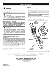
...when blowing dust. n Install the bracket on the miter stand rails and lower the locking lever to secure. n When the correct position is dusty, also wear a dust mask. bracket ADJUSTMENT SCREW See Figure 15. If the saw and bracket assembly can damage, weaken or destroy plastic... removed from the mounting brackets before attempting to remove the saw mounting bracket assemblies (part no. Use of commercial solvents and may create a hazard or cause product damage. A000220601), call Ryobi customer service at any other parts may be able to tighten or loosen the bracket adjustment ...
...when blowing dust. n Install the bracket on the miter stand rails and lower the locking lever to secure. n When the correct position is dusty, also wear a dust mask. bracket ADJUSTMENT SCREW See Figure 15. If the saw and bracket assembly can damage, weaken or destroy plastic... removed from the mounting brackets before attempting to remove the saw mounting bracket assemblies (part no. Use of commercial solvents and may create a hazard or cause product damage. A000220601), call Ryobi customer service at any other parts may be able to tighten or loosen the bracket adjustment ...
Repair Sheet
Page 3
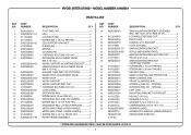
...in 4 WARNING LABEL 2 OPERATOR'S MANUAL (9000225330501) REPAIR SHEET (REV:02) * STANDARD HARDWARE ITEM - MODEL NUMBER A18MS01 PARTS LIST KEY NO. 1 2 3 4 5 6 7 8 9 10 11 12 13 14 15 16 17 18 19 20 21 22 23 ...PART NUMBER A000220601 0131010019 0000220216 0000220210 411072001 0000220307-57 9000225330301 0000220211 414012034 0000220212 410132044 410132035 411012004 0000220309 0000220213 0000220214 0000220803 0000220804 0000220217 A000221501 411012706 412022706 412012704 410032716 9000225330201 983000710 983000710R 4-10-06 DESCRIPTION QTY SAW MOUNTING BRACKET ASSEMBLY (INC. RYOBI MITER STAND...
...in 4 WARNING LABEL 2 OPERATOR'S MANUAL (9000225330501) REPAIR SHEET (REV:02) * STANDARD HARDWARE ITEM - MODEL NUMBER A18MS01 PARTS LIST KEY NO. 1 2 3 4 5 6 7 8 9 10 11 12 13 14 15 16 17 18 19 20 21 22 23 ...PART NUMBER A000220601 0131010019 0000220216 0000220210 411072001 0000220307-57 9000225330301 0000220211 414012034 0000220212 410132044 410132035 411012004 0000220309 0000220213 0000220214 0000220803 0000220804 0000220217 A000221501 411012706 412022706 412012704 410032716 9000225330201 983000710 983000710R 4-10-06 DESCRIPTION QTY SAW MOUNTING BRACKET ASSEMBLY (INC. RYOBI MITER STAND...


