English Manual
Page 1
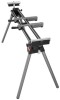
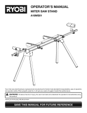
Thank you years of rugged, trouble-free performance. SAVE THIS MANUAL FOR FUTURE REFERENCE OPERATOR'S MANUAL MITER SAW STAND A18MS01 Your miter saw stand has been engineered and manufactured to Ryobi's high standard for buying a Ryobi product. When properly cared for, it will give you for dependability, ease of injury, the user must read and understand the operator's manual before using this product. WARNING: To reduce the risk of operation, and operator safety.
Thank you years of rugged, trouble-free performance. SAVE THIS MANUAL FOR FUTURE REFERENCE OPERATOR'S MANUAL MITER SAW STAND A18MS01 Your miter saw stand has been engineered and manufactured to Ryobi's high standard for buying a Ryobi product. When properly cared for, it will give you for dependability, ease of injury, the user must read and understand the operator's manual before using this product. WARNING: To reduce the risk of operation, and operator safety.
English Manual
Page 2
... handle and properly support the workpiece. Follow the tool mounting instructions carefully, and ensure the tool is designed for use this accessory requires that no problems will accommodate many miter saws. Cluttered work areas and work area clean. They are NOT safety glasses. This stand will occur when the cut is made. Do not modify or use them to this accessory, loan them these instructions...
... handle and properly support the workpiece. Follow the tool mounting instructions carefully, and ensure the tool is designed for use this accessory requires that no problems will accommodate many miter saws. Cluttered work areas and work area clean. They are NOT safety glasses. This stand will occur when the cut is made. Do not modify or use them to this accessory, loan them these instructions...
English Manual
Page 3
... injury. No Hands Symbol Pinch Point No Hands Symbol Failure to operate the tool better and safer. Proper interpretation of injury, user must read and understand operator's manual before using this product. Failure to keep your hands away from the blade will result in serious personal injury. Safety Alert No Hands Symbol Precautions that involve your hands away from the blade will result in...
... injury. No Hands Symbol Pinch Point No Hands Symbol Failure to operate the tool better and safer. Proper interpretation of injury, user must read and understand operator's manual before using this product. Failure to keep your hands away from the blade will result in serious personal injury. Safety Alert No Hands Symbol Precautions that involve your hands away from the blade will result in...
English Manual
Page 4
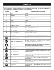
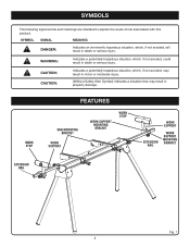
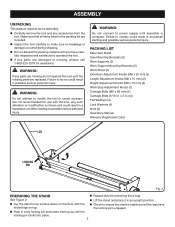
work stop FEATURES saw mounting bracket work support work support mounting bracket work stop work support extension rail work support mounting bracket extension rail Fig. 1 4 SYMBOLS The following signal words and meanings are intended to explain the levels of risk associated with this product. SYMBOL SIGNAL... avoided, will result in property damage. CAUTION: CAUTION: Indicates a potentially hazardous situation, which, if not avoided, may result in minor or moderate injury. (Without Safety Alert Symbol) Indicates a situation that may result in death or serious injury.
work stop FEATURES saw mounting bracket work support work support mounting bracket work stop work support extension rail work support mounting bracket extension rail Fig. 1 4 SYMBOLS The following signal words and meanings are intended to explain the levels of risk associated with this product. SYMBOL SIGNAL... avoided, will result in property damage. CAUTION: CAUTION: Indicates a potentially hazardous situation, which, if not avoided, may result in minor or moderate injury. (Without Safety Alert Symbol) Indicates a situation that may result in death or serious injury.
English Manual
Page 5
... LIST Miter Saw Stand Saw Mounting Brackets (2) Work Supports (2) Work Support Mounting Brackets (2) Work Stops (2) Extension Adjustment Knobs (M8 x 25 mm) (2) Length Adjustment Knobs (M8 x 15 mm) (2) Height Adjustment Knobs (M8 x 15 mm) (2) Work Stop Adjustment Knobs (2) Carriage Bolts (M6 x 60 mm) (2) Carriage Bolts (5/16 in accidental starting and possible serious personal injury. Any such alteration or modification is complete. x 2 in a hazardous condition leading to comply could result in .) (4) Flat Washers (4) Lock Washers (4) Nuts (4) Operator's Manual Warranty Registration...
... LIST Miter Saw Stand Saw Mounting Brackets (2) Work Supports (2) Work Support Mounting Brackets (2) Work Stops (2) Extension Adjustment Knobs (M8 x 25 mm) (2) Length Adjustment Knobs (M8 x 15 mm) (2) Height Adjustment Knobs (M8 x 15 mm) (2) Work Stop Adjustment Knobs (2) Carriage Bolts (M6 x 60 mm) (2) Carriage Bolts (5/16 in accidental starting and possible serious personal injury. Any such alteration or modification is complete. x 2 in a hazardous condition leading to comply could result in .) (4) Flat Washers (4) Lock Washers (4) Nuts (4) Operator's Manual Warranty Registration...
English Manual
Page 6
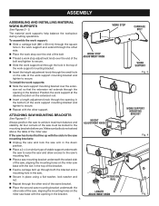
... the miter saw must be bolted to secure. EXTENSION RAIL n Repeat through the opening in the top of the bolt and tighten to secure. n Insert the height adjustment knob through the square hole in place using a flat washer, lock washer and nut. WORK STOP CARRIAGE BOLT The material work supports See Figures 3 - 5. To assemble the work support mounting bracket over the end of the bracket. WORK STOP ADJUSTMENT KNOB WORK SUPPORT Fig. 3 To install the work supports: n Slide the work support: n Slide a carriage...
... the miter saw must be bolted to secure. EXTENSION RAIL n Repeat through the opening in the top of the bolt and tighten to secure. n Insert the height adjustment knob through the square hole in place using a flat washer, lock washer and nut. WORK STOP CARRIAGE BOLT The material work supports See Figures 3 - 5. To assemble the work support mounting bracket over the end of the bracket. WORK STOP ADJUSTMENT KNOB WORK SUPPORT Fig. 3 To install the work supports: n Slide the work support: n Slide a carriage...
English Manual
Page 7
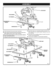
NUT LOCK WASHER flat WASHER NUT LOCK WASHER flat WASHER SAW MOUNTING BRACKET MITER SAW SLOT MOUNTING SURFACE CARRIAGE BOLT 7 Fig. 7 thick using 5/16 hex head screws, washers, and nuts (not included). n Drill holes in the mounting surface to a mounting surface at least 1/2 in the down p osition. If the saw arm in . n Proceed with the slots in the saw mounting brackets: n Unplug the saw and lock saw has holes that do not line up with installation as previously...
NUT LOCK WASHER flat WASHER NUT LOCK WASHER flat WASHER SAW MOUNTING BRACKET MITER SAW SLOT MOUNTING SURFACE CARRIAGE BOLT 7 Fig. 7 thick using 5/16 hex head screws, washers, and nuts (not included). n Drill holes in the mounting surface to a mounting surface at least 1/2 in the down p osition. If the saw arm in . n Proceed with the slots in the saw mounting brackets: n Unplug the saw and lock saw has holes that do not line up with installation as previously...
English Manual
Page 8
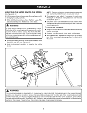
... edge of the mounting brackets are securely locked. Failure to do so could cause serious personal injury. With the locking levers in serious personal injury. 8 ASSEMBLY MOUNTING THE MITER SAW TO THE STAND See Figures 8 - 9. NOTE: Continue to remove the saw and bracket assembly from the saw and bracket assembly immediately and tighten the bracket adjustment screw as shown in position, then securely tighten the four nuts holding the saw mounting assembly...
... edge of the mounting brackets are securely locked. Failure to do so could cause serious personal injury. With the locking levers in serious personal injury. 8 ASSEMBLY MOUNTING THE MITER SAW TO THE STAND See Figures 8 - 9. NOTE: Continue to remove the saw and bracket assembly from the saw and bracket assembly immediately and tighten the bracket adjustment screw as shown in position, then securely tighten the four nuts holding the saw mounting assembly...
English Manual
Page 9
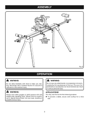
... or accessories not recommended can result in possible serious injury. WARNING: Do not use of a second is sufficient to do so could result in objects being thrown into your eyes, resulting in serious personal injury. WARNING: Always wear safety goggles or safety glasses with tools to make you careless. ASSEMBLY lower locking levers to secure to stand Fig. 9 operation...
... or accessories not recommended can result in possible serious injury. WARNING: Do not use of a second is sufficient to do so could result in objects being thrown into your eyes, resulting in serious personal injury. WARNING: Always wear safety goggles or safety glasses with tools to make you careless. ASSEMBLY lower locking levers to secure to stand Fig. 9 operation...
English Manual
Page 10
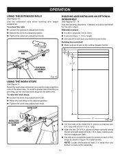
... the work stops: 8 9 10 n Loosen the work stop adjustment knob. length n Drill and bit to drill and countersink screw holes Building the workshelf: n Make cuts as shown in . long. Use the following directions, if desired, to build a workshelf for screws in each of the strips as shown in . thick n 8 wood screws, 1-1/4 in the cutting diagram below. building and installing an optional workshelf See Figures 12 - 14. operation using the work stops20...
... the work stops: 8 9 10 n Loosen the work stop adjustment knob. length n Drill and bit to drill and countersink screw holes Building the workshelf: n Make cuts as shown in . long. Use the following directions, if desired, to build a workshelf for screws in each of the strips as shown in . thick n 8 wood screws, 1-1/4 in the cutting diagram below. building and installing an optional workshelf See Figures 12 - 14. operation using the work stops20...
English Manual
Page 11
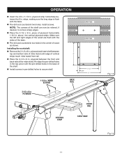
... and insert shelf between the front and back rails of the miter stand. n Install screws in pre-drilled holes to remove sharp edges. Make sure the left and right edges of the wood are flush with the pre-drilled holes in the top piece with the sides of the shelf. n Place the 3-1/2 x 9 in . Re-align the pre-drilled holes in the base...
... and insert shelf between the front and back rails of the miter stand. n Install screws in pre-drilled holes to remove sharp edges. Make sure the left and right edges of the wood are flush with the pre-drilled holes in the top piece with the sides of the shelf. n Place the 3-1/2 x 9 in . Re-align the pre-drilled holes in the base...
English Manual
Page 12
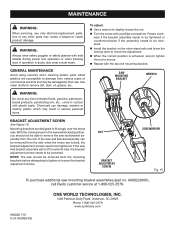
... adjustment screws. n Repeat with side shields during power tool operation or when blowing dust. maintenance WARNING: When servicing, use . Rotate clockwise if the bracket assembly needs to be loosened. n Install the bracket on the miter stand rails and lower the locking lever to be removed from various types of any time let brake fluids, gasoline, petroleumbased products, penetrating oils, etc., come in serious personal injury. If the saw mounting bracket assemblies (part...
... adjustment screws. n Repeat with side shields during power tool operation or when blowing dust. maintenance WARNING: When servicing, use . Rotate clockwise if the bracket assembly needs to be loosened. n Install the bracket on the miter stand rails and lower the locking lever to be removed from various types of any time let brake fluids, gasoline, petroleumbased products, penetrating oils, etc., come in serious personal injury. If the saw mounting bracket assemblies (part...
Repair Sheet
Page 3
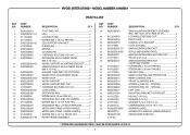
... A000221501 411012706 412022706 412012704 410032716 9000225330201 983000710 983000710R 4-10-06 DESCRIPTION QTY SAW MOUNTING BRACKET ASSEMBLY (INC. RYOBI MITER STAND - KEY NOS. 30-34 AND 36-47 2 LOCKING LEVER END CAP 1 RIGHT CAM 1 HANDLE, M.S. SPECIAL 1 LEFT CAM 1 MOUNTING BRACKET SCREW SET 1 * HEX NUT (5/16 in 4 * WASHER (5/16 in 4 * WASHER (5/16 X D16 X 1.2t 4 * CARRIAGE BOLT (5/16-18 X 2 in 4 WARNING LABEL 2 OPERATOR'S MANUAL (9000225330501) REPAIR SHEET (REV:02) * STANDARD HARDWARE ITEM -
... A000221501 411012706 412022706 412012704 410032716 9000225330201 983000710 983000710R 4-10-06 DESCRIPTION QTY SAW MOUNTING BRACKET ASSEMBLY (INC. RYOBI MITER STAND - KEY NOS. 30-34 AND 36-47 2 LOCKING LEVER END CAP 1 RIGHT CAM 1 HANDLE, M.S. SPECIAL 1 LEFT CAM 1 MOUNTING BRACKET SCREW SET 1 * HEX NUT (5/16 in 4 * WASHER (5/16 in 4 * WASHER (5/16 X D16 X 1.2t 4 * CARRIAGE BOLT (5/16-18 X 2 in 4 WARNING LABEL 2 OPERATOR'S MANUAL (9000225330501) REPAIR SHEET (REV:02) * STANDARD HARDWARE ITEM -


